
Related Manuals for Jäger ADwin-Pro II


Summary of Contents for Jäger ADwin-Pro II
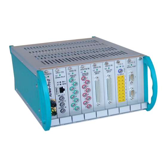
- Page 1 ADwin-Pro II System and hardware description ADwin-Pro II Hardware, manual Dec. 2018...
- Page 2 For any questions, please don’t hesitate to contact us: Hotline: +49 6251 96320 Fax: +49 6251 5 68 19 Jäger Com- E-Mail: info@ADwin.de putergesteuerte Messtechnik GmbH Internet www.ADwin.de Rheinstraße 2-4 D-64653 Lorsch Germany ADwin-Pro II Hardware, manual Dec. 2018...
-
Page 3: Table Of Contents
4 Enclosures for the ADwin-Pro II System ........ -
Page 4: Typographical Conventions
Source code elements such as commands, variables, comments and other Var_1 text are characterized by the font Courier New and are printed in color. Bits in data (here: 16 bit) are referred to as follows: Bit No. … Bit value … Synonym ADwin-Pro II Hardware, manual Dec. 2018... -
Page 5: The Adwin-Pro Ii System
Depending on applications, the different enclosures can be equipped with classic ADwin-Pro I and new ADwin-Pro II modules. When the ADwin-Pro II system was developed great attention was paid to the electromagnetic compatibility. The ADwin-Pro II system and all available input and output modules have the CE sign and can therefore be configured diffe- rently later if necessary. -
Page 6: How To Install An Adwin-Pro Ii System
ADwin How to Install an ADwin-Pro II System How to Install an ADwin-Pro II System 2 How to Install an ADwin-Pro II System Please keep strictly to the following order: 1. Start with the manual "ADwin installation": • Install software and interface drivers from the ADwin-CDROM. -
Page 7: Operating Environment
Close the device for operation, use cover plates to cover gaps between built-in modules. ADwin-Pro II is designed for operation in dry rooms with an ambient tempera- Ambient atmosphere ture of +5°C … +50°C and a relative humidity of 0 … 80% (no condensation). -
Page 8: Enclosures For The Adwin-Pro Ii System
ADwin Enclosures for the ADwin-Pro II System Enclosures for the ADwin-Pro II System 4 Enclosures for the ADwin-Pro II System The different sizes for the enclosures depend on the number of slots and the kind of power supply. Enclosure Number of... -
Page 9: Adwin-Pro Ii
ADwin-Pro II ADwin-Pro II 4.1 ADwin-Pro II The standard enclosure for the ADwin-Pro II systems. The backplane of the 16 slots enclosure connects the processor module with the other modules. The system fuse is located in a slot in the power supply unit above the female connector for the power supply cable (rear of the enclosure). -
Page 10: Adwin-Pro Ii-Dc
ADwin-Pro II-DC 4.2 ADwin-Pro II-DC Pro II-DC The ADwin-Pro II-DC enclosure is similar to the standard enclosure with 16 slots ADwin-Pro II, but is equipped with a DC power supply. If a current-limited power supply unit is used, it should be able to supply a mul- tiple of the idle current during power-up to maintain proper performance of the system. -
Page 11: Adwin-Pro Ii-Bm
ADwin- 230V DIG I/O Fig. 5 – Enclosure of ADwin-Pro II-BM (rear panel) The system fuse is located in a slot in the power supply unit above the female connector for the power supply cable (rear of the enclosure). Number of Slots Main dimensions (l x w x h) 336mm ×... -
Page 12: Adwin-Pro Ii-Light
At the rear of the enclosure, above the power supply connector you will find a label with the revision number: Revision Release Previous versions ADwin-Pro II: New enclosure design and new back Jun. 2006 plane with Pro I and Pro II bus. ADwin-Pro II Hardware, manual Dec. 2018... -
Page 13: Adwin-Pro Ii-Light-Dc
ADwin ADwin-Pro II-light-DC ADwin-Pro II-light-DC 4.5 ADwin-Pro II-light-DC The enclosure ADwin-Pro II-light-DC is similar to ADwin-Pro II-light, but is Pro II-light-DC equipped with a DC power supply. mit 7 Steckplätzen If a current-limited power supply unit is used, it should be able to supply a mul- tiple of the idle current during power-up to maintain proper performance of the system. -
Page 14: Adwin-Pro Ii-Mini
ADwin-Pro II-mini 4.6 ADwin-Pro II-mini Pro II-mini with 5 slots The smallest ADwin-Pro II-mini enclosure has 5 slots and requires an external power supply unit. The power supply connector is located at the rear of the enclosure. Number of Slots Main dimensions (l x w x h) 253mm ×... -
Page 15: Adwin-Pro Modules
4, especially with ADwin-Pro II enclosures. 5.1 Unsupported Pro I modules Normally all Pro I modules are usable in an ADwin-Pro II enclosure if the pro- cessor module Pro-CPU-T11-ENET is used. Nevertheless, the following modules are not supported in ADwin-Pro II systems anyway and can only be used in an ADwin-Pro I system: –... - Page 16 – A fieldbus module uses 32 addresses (group EXT); the address alloca- tion is shown in fig. 13. Settings of DIP switches Set module Addit. allocated address addresses 160…191 192…223 224…255 128…159 Fig. 13 – Address settings of fieldbus modules with DIP switches ADwin-Pro II Hardware, manual Dec. 2018...
-
Page 17: Processor Modules
Pro bus. – Start and run the user defined processes. The processor module provides the memory for data and programs. At the time, the following processor modules are available for ADwin-Pro II: – Pro-CPU-T11-ENET – Pro-CPU-T12 The processor modules can be ordered with the options Pro II-Boot with Storage Device (additional external storage medium) and Pro II-Boot (stand-alone operation of the processor module). - Page 18 ENET-3 Fig. 15 – Pro-CPU-T11-ENET: Front panel The processor module show the mode of operation by LEDs at the Ethernet connector. The meaning of the LEDs is described in manual ADwin Installation, chapter 10.5. ADwin-Pro II Hardware, manual Dec. 2018...
- Page 19 The new instructions have a time unit of 10ns (SLEEP: 100ns). Which instruction is right? Normally is used to bridge the waiting SLEEP time of an I/O instruction, e.g. the settling time of a multiplexer with ADwin-Pro II Hardware, manual Dec. 2018...
- Page 20 1. The processor architecture differs from T9 and T10 in this point: T9 and T10 processed instructions of both groups sequentially. Thus, halting the processor with a SLEEP instruc- tion did make the waiting time for subsequent I/O instructions, too. ADwin-Pro II Hardware, manual Dec. 2018...
- Page 21 The inputs and outputs of the CPU module are comfortably programmed with ADbasic instructions. The instructions are described in ADbasic online help and in the Pro II Software manual. The include file ADwinPro_All.inc contains the following instructions: ADwin-Pro II Hardware, manual Dec. 2018...
- Page 22 (find more in the ADbasic manual). A time diffe- rence determined with will now refer to a part of the total Read_Timer process timing only. For hardware access you may want to use the in- struction as an alternative. Read_Timer_Sync ADwin-Pro II Hardware, manual Dec. 2018...
- Page 23 With a slim device, take the delivered distance piece and attach it to the left side of the storage device. Some storage devices provide jumpers near to the connector strip. If so, take the delivered protective cap and slide the cap over the jumpers. ADwin-Pro II Hardware, manual Dec. 2018...
- Page 24 The clock is set ex works, afterwards the module automatically synchronizes with a time server in the internet as soon as Iinternet access is available. At the moment, the clock cannot be set manually. ADwin-Pro II Hardware, manual Dec. 2018...
- Page 25 Instruction Set up the storage device Storage_Create_Partitions_xxx Storage_Format_xxx Mount the file system Storage_Mount_xxx Storage_Unmount_xxx File operations Storage_File_Create_xxx Storage_File_Delete_xxx Storage_File_Exists_xxx Storage_File_Status_xxx Storage_File_Move_xxx Read or write data Storage_File_Write_xxx Storage_File_Read_xxx Storage_File_Append_xxx Directory operations Storage_Dir_Create_xxx Storage_Dir_Delete_xxx Storage_Dir_Exists_xxx Storage_Dir_Status_xxx ADwin-Pro II Hardware, manual Dec. 2018...
- Page 26 Processor modules Pro II-Boot 5.3.4 Pro II-Boot With Pro II-Boot, you have a boot loader expansion, which can – boot an ADwin-Pro II system. – load up to 10 processes. – start process 10 automatically (if present). – save data.
-
Page 27: Pro Ii: Multi-Io Modules
4MiByte external SRAM 5…30 V (external), 200mA Transistor output Optocouple input 12 s.e. selectable 5V, 12V, 24V MIO-D12 Counter block Universal, 32 Bit, 5V diff. SSI decoder max. 12.5MHz TiCo1 Processor – 56 KiByte internal memory ADwin-Pro II Hardware, manual Dec. 2018... - Page 28 – TiCo processor with 128 KiB internal memory and 4MiB external SRAM memory If the TiCo bootloader is programmed, the module can work on its own and independently from the CPU module of the ADwin-Pro II system. The extended module version Pro II-MIO-4-ET1 Rev. E is described starting on page 31.
- Page 29 4 as inputs or outputs by ADbasic instructions. The chan- nels are configured as inputs after power up. Via the trigger input EVENT a signal can trigger a process, which will be pro- cessed at once and completely (see ADbasic manual). ADwin-Pro II Hardware, manual Dec. 2018...
- Page 30 If you store a TiCoBasic program in the TiCo bootloader, the program is auto- matically loaded into the TiCo processor and started on power-up. Thus, the module can run on its own and independently from the CPU module of the ADwin-Pro II system. ADwin-Pro II Hardware, manual Dec. 2018...
- Page 31 General TiCo processor Processor type: TiCo1 Clock frequency: 50MHz Memory size: 28KiB PM internal, 28KiB DM inter- nal, 4MiByte SRAM external Connector 37-pin D-Sub female connector Fig. 21 – Pro II-MIO-4 Rev. E: Specification ADwin-Pro II Hardware, manual Dec. 2018...
- Page 32 P2_MIO_Digin_Long Use latch register P2_MIO_Dig_Latch P2_MIO_Dig_Read_Latch P2_MIO_Dig_Write_Latch Set and read back output sig- P2_MIO_Digout nals P2_MIO_Digout_Long P2_MIO_Get_Digout_Long General Use LED P2_Check_LED, P2_Set_LED Synchronize P2_Sync_All, P2_Sync_Enable P2_Sync_Stat Use interrupt and event inputs P2_Event_Enable, P2_Event_Read P2_Event_Config ADwin-Pro II Hardware, manual Dec. 2018...
- Page 33 ADbasic online help and in the TiCoBasic manual. Function Instructions Data exchange with the TiCo P2_TDrv_Init processor via global variables P2_GetData_Long, P2_Get_Par, P2_Get_Par_Block P2_SetData_Long, P2_Set_Par, P2_Set_Par_Block P2_Get_TiCo_RingBuffer, P2_Set_TiCo_RingBuffer P2_RingBuffer_Empty P2_RingBuffer_Full ADwin-Pro II Hardware, manual Dec. 2018...
- Page 34 ADwin Pro II: Multi-IO Modules Pro II-MIO-4 Rev. E Function Instructions Control TiCo processor P2_TiCo_Reset, P2_TiCo_Start, P2_TiCo_Stop P2_Get_TiCo_Bootloader_ Status P2_Get_TiCo_Status, P2_Workload Control TiCo processes P2_Process_Status P2_TiCo_Get_Processdelay P2_TiCo_Set_Processdelay P2_TiCo_Start_Process P2_Tico_Stop_Process Transfer TiCo programs P2_TiCo_Flash, P2_TiCo_Load ADwin-Pro II Hardware, manual Dec. 2018...
- Page 35 TiCoBasic. If the TiCo bootloader is programmed, the module can work on its own and independently from the CPU module of the ADwin-Pro II system. The module variant Pro II-MIO-4 Rev. E is described starting on page 24.
- Page 36 Analog Outputs The module Pro II-MIO-4-ET1 Rev. E has 4 analog outputs each with a 16 bit DAC. Each output has a fixed 1st order low-pass filters (fc = 10MHz) to sup- press noise. ADwin-Pro II Hardware, manual Dec. 2018...
- Page 37 EXT VCC and EXT GND. Please not that EXT GND is also used for optocouple inputs. The channels as well as the event-input are optically isolated from system cir- cuitry. ADwin-Pro II Hardware, manual Dec. 2018...
- Page 38 Via the two pins U1 IN you can supply a voltage, which is then available at the pins U1 OUT e.g. for external incremental encoders. The maximum current at each of the output pins is 100mA; there is an appropriate fuse between each input and output pin. ADwin-Pro II Hardware, manual Dec. 2018...
- Page 39 PWM counter to create a solution. You find a description of PWM registers on page 140 (module Pro II-CNT-x Rev. E). Use the evaluation with PWM registers for special solutions only. ADwin-Pro II Hardware, manual Dec. 2018...
- Page 40 C:\ADwin\Fieldbus\EtherCAT\ to the directory of the con- figuration tool. TiCo processor The module provides the freely programmable TiCo processor with 64kiB pro- gram memory, 64kiB data memory, and 4MiB external SRAM memory. The ADwin-Pro II Hardware, manual Dec. 2018...
- Page 41 8 channel with TTL logic, configurable in groups of 4 channels Pull down resistor 10kΩ min. 2V max. 0.8V max. 1µA max. 0.01mA Voltage range -0.5V … +5.5V Fig. 29 – Pro II-MIO-4-ET1 Rev. E: Specification ADwin-Pro II Hardware, manual Dec. 2018...
- Page 42 Isolation none SSI Decoder Number Clock frequency SSI 6kHz … 12.5MHz deccoder (CLK) Ethercat Interface Number 1, to be programmed in TiCoBasic General Fig. 29 – Pro II-MIO-4-ET1 Rev. E: Specification ADwin-Pro II Hardware, manual Dec. 2018...
- Page 43 P2_Write_DAC, P2_Write_DAC4 P2_Write_DAC4_Packed P2_Write_DAC32 P2_Start_DAC Digital Inputs / Outputs Configure input/outputs P2_MIO_DigProg Query input signals P2_MIO_Digin_Long Use latch register P2_MIO_Dig_Latch P2_MIO_Dig_Read_Latch P2_MIO_Dig_Write_Latch Set and read back output sig- P2_MIO_Digout nals P2_MIO_Digout_Long P2_MIO_Get_Digout_Long Transistor Outputs ADwin-Pro II Hardware, manual Dec. 2018...
- Page 44 Set inputs to single-ended or SE_Diff differential Do a single conversion – com- ADC, ADC24 plete or step by step Set_Mux, Start_Conv, Wait_EOC Read_ADC, Read_ADC24 Read value and start new con- Read_ADC_SConv version Read_ADC_SConv24 ADwin-Pro II Hardware, manual Dec. 2018...
- Page 45 Cnt_Read_Latch Use PWM counter Cnt_PW_Enable, Cnt_PW_Latch Cnt_Get_PW_HL P2_Cnt_Read_Int_Register SSI Decoder Use SSI decoder SSI_Mode, SSI_Set_Bits SSI_Set_Clock SSI_Set_Delay, SSI_Read SSI_Start, SSI_Status EtherCat Interface Use interface MIO_ECAT_Init MIO_ECAT_Get_Driver_Version MIO_ECAT_Check_State_Transition MIO_ECAT_Read_Data_16L MIO_ECAT_Write_Data_16L General Use LED Check_LED, Set_LED ADwin-Pro II Hardware, manual Dec. 2018...
- Page 46 ADwin Pro II: Multi-IO Modules Pro II-MIO-4-ET1 Rev. E Range Instructions Use interrupt and event inputs Event_Enable, Event_Read Event_Config, Trigger_Event ADwin-Pro II Hardware, manual Dec. 2018...
- Page 47 P2_GetData_Long, P2_Get_Par, P2_Get_Par_Block P2_SetData_Long, P2_Set_Par, P2_Set_Par_Block P2_Get_TiCo_RingBuffer, P2_Set_TiCo_RingBuffer P2_RingBuffer_Empty P2_RingBuffer_Full Control TiCo processor P2_TiCo_Reset, P2_TiCo_Start, P2_TiCo_Stop P2_Get_TiCo_Bootloader_ Status P2_Get_TiCo_Status, P2_Workload Control TiCo processes P2_Process_Status P2_TiCo_Get_Processdelay P2_TiCo_Set_Processdelay P2_TiCo_Start_Process P2_Tico_Stop_Process Transfer TiCo programs P2_TiCo_Flash, P2_TiCo_Load ADwin-Pro II Hardware, manual Dec. 2018...
- Page 48 – 1 SSI decoder to connect an incremental encoder – TiCo processor with 56 KiByte internal memory If the TiCo bootloader is programmed, the module can work on its own and independently from the CPU module of the ADwin-Pro II system. VCC TRA 6...11 OUT 100mA SSI CLK–...
- Page 49 The module can automatically monitor the edges of input channels. With every change, the current input levels are saved together with a time stamp in a FIFO. The FIFO data can be read and processed. ADwin-Pro II Hardware, manual Dec. 2018...
- Page 50 PWM counter to evaluate high and low times, duty cycle, or frequency. Both counters of a block can be operated in parallel. Counter 1 inputs run differential, counter 2 hsa optically isolated inputs (single ended). ADwin-Pro II Hardware, manual Dec. 2018...
- Page 51 PWM counter to create a solution. You find a description of PWM registers on page 140 (module Pro II-CNT-x Rev. E). Use the evaluation with PWM registers for special solutions only. ADwin-Pro II Hardware, manual Dec. 2018...
- Page 52 Reference frequency 100MHz PWM analysis Input / output level 1 counter compatible to RS422/485 (5V differen- tial, 120 Ω bus terminating resistor) 1 counter via optocouples Fig. 33 – Pro II-MIO-D12 Rev. E: Specification ADwin-Pro II Hardware, manual Dec. 2018...
- Page 53 P2_Digout_FIFO_Start P2_Digout_FIFO_Write Optocouple Inputs Query input signals P2_Digin_Edge P2_MIO_Digin_Long Use latch register P2_MIO_Dig_Latch, P2_Sync_All P2_MIO_Dig_Read_Latch Control edges at input chan- P2_Dig_FIFO_Mode nels P2_Digin_FIFO_Enable P2_Digin_FIFO_Read P2_Digin_FIFO_Read_Fast P2_Digin_FIFO_Read_Timer P2_Digin_FIFO_Clear P2_Digin_FIFO_Full Counter Block Configure counter P2_Cnt_Enable, P2_Cnt_Mode ADwin-Pro II Hardware, manual Dec. 2018...
- Page 54 Configure counter Cnt_Enable, Cnt_Mode Use counter Cnt_Clear, Cnt_Get_Status Cnt_Latch, Cnt_Read Cnt_Read_Int_Register Cnt_Sync_Latch, Cnt_Read_Latch Use PWM counter Cnt_PW_Enable, Cnt_PW_Latch Cnt_Get_PW_HL Cnt_PW_Enable, Cnt_PW_Latch Cnt_Get_PW_HL P2_Cnt_Read_Int_Register SSI Decoder Use SSI decoder SSI_Mode, SSI_Set_Bits SSI_Set_Clock SSI_Set_Delay, SSI_Read SSI_Start, SSI_Status ADwin-Pro II Hardware, manual Dec. 2018...
- Page 55 P2_GetData_Long, P2_Get_Par, P2_Get_Par_Block P2_SetData_Long, P2_Set_Par, P2_Set_Par_Block P2_Get_TiCo_RingBuffer, P2_Set_TiCo_RingBuffer P2_RingBuffer_Empty P2_RingBuffer_Full Control TiCo processor P2_TiCo_Reset, P2_TiCo_Start, P2_TiCo_Stop P2_Get_TiCo_Bootloader_ Status P2_Get_TiCo_Status, P2_Workload Control TiCo processes P2_Process_Status P2_TiCo_Get_Processdelay P2_TiCo_Set_Processdelay P2_TiCo_Start_Process P2_Tico_Stop_Process Transfer TiCo programs P2_TiCo_Flash, P2_TiCo_Load ADwin-Pro II Hardware, manual Dec. 2018...
-
Page 56: Pro Ii: Analog Input Modules
ADwin Pro II: Analog Input Modules 5.5 Pro II: Analog Input Modules This section describes analog input modules for ADwin-Pro II. Analog input modules for ADwin-Pro I be found in the manual "ADwin-Pro Hardware" on page 18 ff. Module name... - Page 57 The module can control an upper and lower limit for each channel separately. 100k 100k 100k InAmp 100k Data data Registers Sequence Address 100k control addr. Control Decoder 100k Fig. 34 – Pro II-AIn-8/18 Rev. E: Block diagram ADwin-Pro II Hardware, manual Dec. 2018...
- Page 58 RESERVED RESERVED connector AGND AGND +5V (OUT, <0.1A) EVENT AGND Fig. 36 – Pro II-AIn-8/18 Rev. E: Pin assignment AIN8/18 AIN-8/18 ANALOG ANALOG INPUT INPUT Fig. 37 – Pro II-AIn-8/18 Rev. E: Front panels ADwin-Pro II Hardware, manual Dec. 2018...
- Page 59 ADbasic online help and in the TiCoBasic manual. Function Instructions Data exchange with the TiCo P2_TDrv_Init processor via global variables P2_GetData_Long, P2_Get_Par, P2_Get_Par_Block P2_SetData_Long, P2_Set_Par, P2_Set_Par_Block P2_Get_TiCo_RingBuffer, P2_Set_TiCo_RingBuffer P2_RingBuffer_Empty P2_RingBuffer_Full ADwin-Pro II Hardware, manual Dec. 2018...
- Page 60 Pro II: Analog Input Modules Pro II-AIn-8/18 Rev. E Function Instructions Control TiCo processor P2_TiCo_Reset, P2_TiCo_Start, P2_TiCo_Stop P2_Get_TiCo_Bootloader_ Status P2_Get_TiCo_Status, P2_Workload Control TiCo processes P2_Process_Status P2_TiCo_Get_Processdelay P2_TiCo_Set_Processdelay P2_TiCo_Start_Process P2_Tico_Stop_Process Transfer TiCo programs P2_TiCo_Flash, P2_TiCo_Load ADwin-Pro II Hardware, manual Dec. 2018...
- Page 61 32 single ended or 16 differential; via multiplexer Resolution: 18 bit Conversion time: max. 2µs Sampling rate: max. 500ksps Multiplexer settling time: 2.5µs Measurement range: ±10V Fig. 39 – Pro II-AIn-32/18-D Rev. E: Specification ADwin-Pro II Hardware, manual Dec. 2018...
- Page 62 Programming in ADbasic The module is comfortably programmed with ADbasic instructions. The instructions are described in ADbasic online help and in the Pro II Software manual. The include file ADwinPro_All.inc contains instructions for the following functions: ADwin-Pro II Hardware, manual Dec. 2018...
- Page 63 The module can be programmed with TiCoBasic instructions. The instructions Programming in are described in TiCoBasic online help. TiCoBasic The include file AInTiCo.inc contains instructions for the following functions: Function Instruction Set inputs to s.e. or differential SE_Diff ADwin-Pro II Hardware, manual Dec. 2018...
- Page 64 ADC, ADC24 plete or step by step Set_Mux, Start_Conv, Wait_EOC Read_ADC, Read_ADC24 Read value and start new con- Read_ADC_SConv version Read_ADC_SConv24 Use LED Check_LED, Set_LED Use interrupt and event inputs Event_Enable, Event_Read Event_Config, Trigger_Event ADwin-Pro II Hardware, manual Dec. 2018...
- Page 65 ±0.05% of measured voltage by input resis- tance max. ±1 LSB ±0.05% of measured voltage by input resis- tance Input resistance: 500kΩ, ±0.05% Input over-voltage: ±15V Fig. 44 – Pro II-AIn-16/18-C Rev. E: Specification ADwin-Pro II Hardware, manual Dec. 2018...
- Page 66 Do a single conversion – com- P2_ADC, P2_ADC24 plete or step by step P2_Set_Mux, P2_Start_Conv P2_Wait_EOC P2_Read_ADC, P2_Read_ADC24 Read value and start new con- P2_Read_ADC_SConv version P2_Read_ADC_SConv24 Use sequence control P2_Seq_Init, P2_Seq_Start P2_Seq_Read, P2_Seq_Read24 P2_Seq_Read24_Packed P2_Seq_Wait ADwin-Pro II Hardware, manual Dec. 2018...
- Page 67 ADwin Pro II: Analog Input Modules Pro II-AIn-16/18-C Rev. E Function Instructions Control input limits P2_ADC_Read_Limit P2_ADC_Set_Limit Synchronize P2_Sync_All Use LED P2_Check_LED, P2_Set_LED Use interrupt and event inputs P2_Event_Enable, P2_Event_Read P2_Event_Config, P2_Event2_Config ADwin-Pro II Hardware, manual Dec. 2018...
- Page 68 ±4 LSB typical max. ±1 LSB Input resistance 330kΩ, ±2% Input over-voltage ±35V Offset error adjustable Offset drift ±30ppm/ºC Connector 37-pin D-Sub female connector Module width 15 HP Fig. 47 – Pro II-AIn-8/18-8B Rev. E: Specification ADwin-Pro II Hardware, manual Dec. 2018...
- Page 69 P2_Set_Mux, P2_Start_Conv P2_Wait_EOC P2_Read_ADC, P2_Read_ADC24 Read value and start new con- P2_Read_ADC_SConv version P2_Read_ADC_SConv24 Use sequence control P2_Seq_Init, P2_Seq_Start P2_Seq_Read, P2_Seq_Read24 P2_Seq_Read24_Packed P2_Seq_Wait Control input limits P2_ADC_Read_Limit P2_ADC_Set_Limit Synchronize P2_Sync_All Use LED P2_Check_LED, P2_Set_LED ADwin-Pro II Hardware, manual Dec. 2018...
- Page 70 ADwin Pro II: Analog Input Modules Pro II-AIn-8/18-8B Rev. E Function Instructions Use interrupt and event inputs P2_Event_Enable, P2_Event_Read P2_Event_Config, P2_Event2_Config ADwin-Pro II Hardware, manual Dec. 2018...
- Page 71 ±4 LSB typical max. ±1 LSB Input resistance 330kΩ, ±2% Input over-voltage ±35V Offset error adjustable Offset drift ±30ppm/ºC Connector 37-pin D-Sub female connector Module width 15 HP Fig. 50 – Pro II-AIn-16/18-8B Rev. E: Specification ADwin-Pro II Hardware, manual Dec. 2018...
- Page 72 P2_ADC24 plete or step by step P2_Set_Mux, P2_Start_Conv P2_Wait_EOC P2_Read_ADC, P2_Read_ADC24 Read value and start new con- P2_Read_ADC_SConv version P2_Read_ADC_SConv24 Use sequence control P2_Seq_Init, P2_Seq_Start P2_Seq_Read, P2_Seq_Read24 P2_Seq_Read24_Packed P2_Seq_Wait Control input limits P2_ADC_Read_Limit P2_ADC_Set_Limit ADwin-Pro II Hardware, manual Dec. 2018...
- Page 73 ADwin Pro II: Analog Input Modules Pro II-AIn-16/18-8B Rev. E Function Instructions Synchronize P2_Sync_All Use LED P2_Check_LED, P2_Set_LED Use interrupt and event inputs P2_Event_Enable, P2_Event_Read P2_Event_Config, P2_Event2_Config ADwin-Pro II Hardware, manual Dec. 2018...
- Page 74 Event Inputs With module version Pro II-AIn-F-4/14-D Rev. E (D-Sub female connector), a burst sequence can be controlled by external event signals, i.e. each (result- ing) event signal has a measurement value stored. ADwin-Pro II Hardware, manual Dec. 2018...
- Page 75 16MHz Connector 4 LEMO female connectors. 1-pole, or 4 LEMO female connectors. 2-pole, or 37-pin D-Sub female connector, or 4 BNC female connectors. Fig. 54 – Pro II-AIn-F-4/14 Rev. E: Specification ADwin-Pro II Hardware, manual Dec. 2018...
- Page 76 The include file ADwinPro_All.inc contains instructions for the following functions: Function Instructions Configure sequence control P2_ADCF_Mode Do a single conversion – com- P2_ADCF plete or step by step P2_Start_Conv, P2_Wait_EOCF P2_Read_ADCF Read several values P2_Read_ADCF32, P2_Read_ADCF4 P2_Read_ADCF4_Packed ADwin-Pro II Hardware, manual Dec. 2018...
- Page 77 Use burst conversion P2_Burst_Init P2_Burst_Start, P2_Burst_Stop P2_Burst_Status, P2_Burst_Reset P2_Burst_Read P2_Burst_Read_Index, P2_Burst_Read_Index P2_Burst_Read_Unpacked1/2/4 P2_Burst_CRead_Unpacked1/2/4 P2_Burst_CRead_Pos_Unpacked1/2/4 Synchronize P2_Sync_All, P2_Sync_Enable P2_Sync_Stat Control input limits P2_ADCF_Read_Limit P2_ADCF_Set_Limit Use LED P2_Check_LED, P2_Set_LED Use interrupt and event inputs P2_Event_Enable, P2_Event_Read P2_Event_Config, P2_Event2_Config ADwin-Pro II Hardware, manual Dec. 2018...
- Page 78 The probability of a delay rises with the block size. – The time offset between continuous conversion and blockwise reading demands a data buffer. Therefore, the initialization of the burst sequence must allocate sufficient memory range (P2_Burst_Init, parameter samples). ADwin-Pro II Hardware, manual Dec. 2018...
- Page 79 Connector 8 LEMO female connectors. 1-pole, or 8 LEMO female connectors. 2-pole, or 37-pin D-Sub female connector, or 8 BNC female connectors. Module width 10 HP Fig. 58 – Pro II-AIn-F-8/14 Rev. E: Specification ADwin-Pro II Hardware, manual Dec. 2018...
- Page 80 Configure sequence control P2_ADCF_Mode Do a single conversion – com- P2_ADCF plete or step by step P2_Start_Conv, P2_Wait_EOCF P2_Read_ADCF Read several values P2_Read_ADCF32 P2_Read_ADCF4, P2_Read_ADCF8 P2_Read_ADCF4_Packed P2_Read_ADCF8_Packed Read value and start new con- P2_Read_ADC_SConv version P2_Read_ADC_SConv32 ADwin-Pro II Hardware, manual Dec. 2018...
- Page 81 P2_Burst_Stop P2_Burst_Status, P2_Burst_Reset P2_Burst_Read P2_Burst_Read_Index, P2_Burst_Read_Index P2_Burst_Read_Unpacked1/2/4/8 P2_Burst_CRead_Unpacked1/2/4/8 P2_Burst_CRead_Pos_Unpacked1/2/4/8 Synchronize P2_Sync_All, P2_Sync_Enable P2_Sync_Mode, P2_Sync_Stat Control input limits P2_ADCF_Read_Limit P2_ADCF_Set_Limit P2_ADCF_Reset_Min_Max, P2_ADCF_Read_Min_Max4 Use LED P2_Check_LED, P2_Set_LED Use interrupt and event inputs P2_Event_Enable, P2_Event_Read P2_Event_Config, P2_Event2_Config ADwin-Pro II Hardware, manual Dec. 2018...
- Page 82 With a continuous burst-sequence, the measuring rate must be syntonized to the reading rate. Please note: – Measurement values are always read in blocks, the block size is select- able. The greater the data blocks are, the faster the average reading is done. ADwin-Pro II Hardware, manual Dec. 2018...
- Page 83 Offset error adjustable Offset drift ±30ppm/ºC of full scale range Event input (D-Sub only) 3 differential; RS422/485 compatible (5 V differential, 120 Ω bus terminating resistor) Fig. 62 – Pro II-AIn-F-4/16 Rev. E: Specification ADwin-Pro II Hardware, manual Dec. 2018...
- Page 84 The include file ADwinPro_All.inc contains instructions for the following functions: Function Instructions Configure sequence control P2_ADCF_Mode, P2_Set_Average_Filter, P2_Set_Gain Do a single conversion – com- P2_ADCF plete or step by step P2_Start_ConvF, P2_Wait_EOCF P2_Read_ADCF ADwin-Pro II Hardware, manual Dec. 2018...
- Page 85 P2_Burst_Status, P2_Burst_Reset P2_Burst_Read P2_Burst_Read_Index, P2_Burst_Read_Index P2_Burst_Read_Unpacked1/2/4 P2_Burst_CRead_Unpacked1/2/4 P2_Burst_CRead_Pos_Unpacked1/2/4 Synchronize P2_Sync_All, P2_Sync_Enable P2_Sync_Mode, P2_Sync_Stat Control input limits P2_ADCF_Read_Limit P2_ADCF_Set_Limit P2_ADCF_Reset_Min_Max, P2_ADCF_Read_Min_Max4, P2_ADCF_Read_Min_Max8 Use LED P2_Check_LED, P2_Set_LED Use interrupt and event inputs P2_Event_Enable, P2_Event_Read P2_Event_Config, P2_Event2_Config ADwin-Pro II Hardware, manual Dec. 2018...
- Page 86 ADwin system. The measurement values–number and measuring rate to be defined ahead in the program–are stored in the burst-memory of the module. The processor module then reads the stored values (even during a ADwin-Pro II Hardware, manual Dec. 2018...
- Page 87 1, 2, 4, 8 software selectable Accuracy typical ±1.2 LSB, max. ±5 LSB typical ±0.5 LSB, max. ±1 LSB Input resistance 330kΩ, ±2% Input over-voltage ±20V Offset error adjustable Fig. 66 – Pro II-AIn-F-8/16 Rev. E: Specification ADwin-Pro II Hardware, manual Dec. 2018...
- Page 88 The module is comfortably programmed with ADbasic instructions. The instructions are described in ADbasic online help and in the Pro II Software manual. The include file ADwinPro_All.inc contains instructions for the following functions: Function Instructions Configure sequence control P2_ADCF_Mode, P2_Set_Average_Filter, P2_Set_Gain ADwin-Pro II Hardware, manual Dec. 2018...
- Page 89 P2_Burst_Read_Index P2_Burst_Read_Unpacked1/2/4/8 P2_Burst_CRead_Unpacked1/2/4/8 P2_Burst_CRead_Pos_Unpacked1/2/4/8 Synchronize P2_Sync_All, P2_Sync_Enable P2_Sync_Stat Control input limits P2_ADCF_Read_Limit P2_ADCF_Set_Limit Provide maximum and P2_ADCF_Reset_Min_Max minimum values P2_ADCF_Read_Min_Max4 P2_ADCF_Read_Min_Max8 Use LED P2_Check_LED, P2_Set_LED Use interrupt and event inputs P2_Event_Enable, P2_Event_Read P2_Event_Config, P2_Event2_Config ADwin-Pro II Hardware, manual Dec. 2018...
- Page 90 With module versions -L2 (2-pole Lemo) and -D (D-Sub connector), the enclo- sure’s ground is also available at the shield of the connectors. Buffer Front (PE) Fig. 70 – Pro II-AIn-F-4/18 Rev. E: Input circuitry ADwin-Pro II Hardware, manual Dec. 2018...
- Page 91 D-Sub connector type EGG Fig. 72 – Pro II-AIn-F-4/18 Rev. E: Pin assignment differential AIn-F4/18 AIN-F4/18 AIN-F4/18 AIn-F4/18 ANALOG ANALOG ANALOG ANALOG INPUT INPUT INPUT INPUT Fig. 73 – Pro II-AIn-F-4/18 Rev. E: Front panels ADwin-Pro II Hardware, manual Dec. 2018...
- Page 92 P2_Read_ADCF4_24B P2_Read_ADCF4_Packed Read value and start new con- P2_Read_ADC_SConv version P2_Read_ADC_SConv24 P2_Read_ADC_SConv32 Synchronize P2_Sync_All, P2_Sync_Enable P2_Sync_Stat Control input limits P2_ADCF_Read_Limit P2_ADCF_Set_Limit Use LED P2_Check_LED, P2_Set_LED Use interrupt and event inputs P2_Event_Enable, P2_Event_Read P2_Event_Config, P2_Event2_Config ADwin-Pro II Hardware, manual Dec. 2018...
- Page 93 With module versions -L2 (2-pole Lemo) and -D (D-Sub connector), the enclo- sure’s ground is also available at the shield of the connectors. Buffer Front (PE) Fig. 75 – Pro II-AIn-F-8/18 Rev. E: Input circuitry ADwin-Pro II Hardware, manual Dec. 2018...
- Page 94 D-Sub connector type EGG Fig. 77 – Pro II-AIn-F-8/18 Rev. E: Pin assignment differential AIn-F8/18 AIN-F8/18 AIN-F8/18 AIN-F8/18 ANALOG ANALOG ANALOG ANALOG INPUT INPUT INPUT INPUT Fig. 78 – Pro II-AIn-F-8/18 Rev. E: Front panels ADwin-Pro II Hardware, manual Dec. 2018...
- Page 95 P2_Read_ADCF8_24B P2_Read_ADCF8_Packed Read value and start new con- P2_Read_ADC_SConv version P2_Read_ADC_SConv24 P2_Read_ADC_SConv32 Synchronize P2_Sync_All, P2_Sync_Enable P2_Sync_Stat Control input limits P2_ADCF_Read_Limit P2_ADCF_Set_Limit Use LED P2_Check_LED, P2_Set_LED Use interrupt and event inputs P2_Event_Enable, P2_Event_Read P2_Event_Config, P2_Event2_Config ADwin-Pro II Hardware, manual Dec. 2018...
-
Page 96: Pro Ii: Analog Output Modules
ADwin Pro II: Analog Output Modules 5.6 Pro II: Analog Output Modules This section describes analog output modules for ADwin-Pro II. Analog output modules for ADwin-Pro I be found in the manual "ADwin-Pro Hardware" from page 65. AOut 4/16- AOut 8/16-... - Page 97 Fig. 79 – Pro II-AOut-4/16 Rev. E: Block diagram Output channels 4 single-ended Resolution 16 bit Settling time to 0.01% FSR < 3µs Output voltage ±10V Fig. 80 – Pro II-AOut-4/16 Rev. E: Specification ADwin-Pro II Hardware, manual Dec. 2018...
- Page 98 D-Sub connector type EGG Fig. 81 – Pro II-AOut-4/16 Rev. E: Pin assignment AOUT4/16 AOUT4/16 AOUT4/16 AOUT4/16 ANALOG ANALOG ANALOG ANALOG OUTPUT OUTPUT OUTPUT OUTPUT Fig. 82 – Pro II-AOut-4/16 Rev. E: Front covers ADwin-Pro II Hardware, manual Dec. 2018...
- Page 99 P2_GetData_Long, P2_Get_Par, P2_Get_Par_Block P2_SetData_Long, P2_Set_Par, P2_Set_Par_Block P2_Get_TiCo_RingBuffer, P2_Set_TiCo_RingBuffer P2_RingBuffer_Empty P2_RingBuffer_Full Control TiCo processor P2_TiCo_Reset, P2_TiCo_Start, P2_TiCo_Stop P2_Get_TiCo_Bootloader_ Status P2_Get_TiCo_Status, P2_Workload Control TiCo processes P2_Process_Status P2_TiCo_Get_Processdelay P2_TiCo_Set_Processdelay P2_TiCo_Start_Process P2_Tico_Stop_Process Transfer TiCo programs P2_TiCo_Flash, P2_TiCo_Load ADwin-Pro II Hardware, manual Dec. 2018...
- Page 100 Fig. 83 – Pro II-AOut-8/16 Rev. E: Block diagram Output channels 8 single-ended Resolution 16 bit Settling time to 0.01% FSR < 3µs Output voltage ±10V Fig. 84 – Pro II-AOut-8/16 Rev. E: Specification ADwin-Pro II Hardware, manual Dec. 2018...
- Page 101 D-Sub connector type EGG Fig. 85 – Pro II-AOut-8/16 Rev. E: Pin assignment AOUT-8/16 AOUT-8/16 AOUT8/16 AOUT8/16 ANALOG ANALOG ANALOG ANALOG OUTPUT OUTPUT OUTPUT OUTPUT Fig. 86 – Pro II-AOut-8/16 Rev. E: Front covers ADwin-Pro II Hardware, manual Dec. 2018...
- Page 102 P2_GetData_Long, P2_Get_Par, P2_Get_Par_Block P2_SetData_Long, P2_Set_Par, P2_Set_Par_Block P2_Get_TiCo_RingBuffer, P2_Set_TiCo_RingBuffer P2_RingBuffer_Empty P2_RingBuffer_Full Control TiCo processor P2_TiCo_Reset, P2_TiCo_Start, P2_TiCo_Stop P2_Get_TiCo_Bootloader_ Status P2_Get_TiCo_Status, P2_Workload Control TiCo processes P2_Process_Status P2_TiCo_Get_Processdelay P2_TiCo_Set_Processdelay P2_TiCo_Start_Process P2_Tico_Stop_Process Transfer TiCo programs P2_TiCo_Flash, P2_TiCo_Load ADwin-Pro II Hardware, manual Dec. 2018...
- Page 103 The combination of consecutive ramps enables the output of curves. In addition to a voltage ramp, at the start and/or at the end of the ramp TTL signals can be set at the 16 digital outputs. ADwin-Pro II Hardware, manual Dec. 2018...
- Page 104 ±8 LSB max. ±1 LSB typically Offset error adjustable Gain error adjustable Offset drift ±10 µV/°K Digital Inputs/Outputs Digital inputs/outputs 16 inputs and 16 outputs with TTL logic Fig. 88 – Pro II-AOut-1/16 Rev. E: Specification ADwin-Pro II Hardware, manual Dec. 2018...
- Page 105 Fifo P2_Digout_Fifo_Read_Timer P2_Digout_Fifo_Empty P2_Dig_Fifo_Mode P2_Digout_Fifo_Start P2_Digout_Fifo_Enable P2_Digout_Fifo_Write Ramp mode P2_DAC_Ramp_Write P2_DAC_Ramp_Status P2_DAC_Ramp_Buffer_Free P2_DAC_Ramp_Stop Digital I/Os Query input signalst P2_Digin_Long Monitor edges of input chan- P2_Digin_Fifo_Clear nels P2_Digin_Fifo_Read P2_Digin_Fifo_Read_Fast P2_Digin_Fifo_Read_Timer P2_Digin_Fifo_Full P2_Digin_Fifo_Enable ADwin-Pro II Hardware, manual Dec. 2018...
- Page 106 Digin_Fifo_Full Digin_Fifo_Enable Set and read back output sig- Digout, Digout_Long nals Get_Digout_Long Digout_Bits Digout_Set, Digout_Reset Use latch register Dig_Latch Dig_Read_Latch Dig_Write_Latch General Use LED Check_LED, Set_LED Use interrupt and event inputs Event_Enable, Event_Read Event_Config ADwin-Pro II Hardware, manual Dec. 2018...
- Page 107 P2_GetData_Long, P2_Get_Par, P2_Get_Par_Block P2_SetData_Long, P2_Set_Par, P2_Set_Par_Block P2_Get_TiCo_RingBuffer, P2_Set_TiCo_RingBuffer P2_RingBuffer_Empty P2_RingBuffer_Full Control TiCo processor P2_TiCo_Reset, P2_TiCo_Start, P2_TiCo_Stop P2_Get_TiCo_Bootloader_ Status P2_Get_TiCo_Status, P2_Workload Control TiCo processes P2_Process_Status P2_TiCo_Get_Processdelay P2_TiCo_Set_Processdelay P2_TiCo_Start_Process P2_Tico_Stop_Process Transfer TiCo programs P2_TiCo_Flash, P2_TiCo_Load ADwin-Pro II Hardware, manual Dec. 2018...
-
Page 108: Pro Ii: Digital-I/O Modules
TiCo1 – CNT-T processor with TiCo1 5, 12, 24 CNT-I processor 4 + 2 SSI, RS422/ with TiCo1 5 diff. – CNT-D RS485 processor a. U: Universal counter = UD + I + PWM ADwin-Pro II Hardware, manual Dec. 2018... - Page 109 Fig. 90 – Pro II-DIO-32 Rev. E: Front panel and Pin assignment Digital inputs TTL logic Input/output channels 32; programmable via software as inputs/outputs in blocks of Pull down resistor 10kΩ Fig. 91 – Pro II-DIO-32 Rev. E: Specification ADwin-Pro II Hardware, manual Dec. 2018...
- Page 110 P2_Digin_FIFO_Full Query edges of input channels P2_Digin_Edge Set and read back output sig- P2_Digout, P2_Digout_Bits nals P2_Digout_Long P2_Get_Digout_Long Synchronize P2_Sync_All, P2_Sync_Enable P2_Sync_Stat Use LED P2_Check_LED, P2_Set_LED Use interrupt and event inputs P2_Event_Enable, P2_Event_Read P2_Event_Config ADwin-Pro II Hardware, manual Dec. 2018...
- Page 111 Bus- Trans- D00:07 ceiver Bus- Trans- D08:15 ceiver Data Data Register Bus- Trans- D16:23 ceiver Bus- Trans- D24:31 ceiver EVENT DIO 32 RB Fig. 92 – Pro II-DIO-32-TiCo Rev. E: Block diagram ADwin-Pro II Hardware, manual Dec. 2018...
- Page 112 ADbasic online help and Pro II Software manual. The include file ADwinPro_All.inc contains instructions for the following functions: Function Instructions Configure input/outputs P2_DigProg Query input signals P2_Digin_Long Use latch register P2_Dig_Latch P2_Dig_Read_Latch P2_Dig_Write_Latch ADwin-Pro II Hardware, manual Dec. 2018...
- Page 113 Set and read back output sig- Digout, Digout_Bits nals Digout_Set, Digout_Reset Digout_Long Get_Digout_Long Set output signals automati- Digout_FIFO_Clear cally Digout_FIFO_Empty Digout_FIFO_Enable Digout_FIFO_Read_Timer Digout_FIFO_Start Digout_FIFO_Write Use LED Check_LED, Set_LED Use interrupt and event inputs Event_Enable, Trigger_Event Event_Config ADwin-Pro II Hardware, manual Dec. 2018...
- Page 114 P2_GetData_Long, P2_Get_Par, P2_Get_Par_Block P2_SetData_Long, P2_Set_Par, P2_Set_Par_Block P2_Get_TiCo_RingBuffer, P2_Set_TiCo_RingBuffer P2_RingBuffer_Empty P2_RingBuffer_Full Control TiCo processor P2_TiCo_Reset, P2_TiCo_Start, P2_TiCo_Stop P2_Get_TiCo_Bootloader_ Status P2_Get_TiCo_Status, P2_Workload Control TiCo processes P2_Process_Status P2_TiCo_Get_Processdelay P2_TiCo_Set_Processdelay P2_TiCo_Start_Process P2_Tico_Stop_Process Transfer TiCo programs P2_TiCo_Flash, P2_TiCo_Load ADwin-Pro II Hardware, manual Dec. 2018...
- Page 115 The Fifo can either be used for edge control of the inputs or for level output at the outputs. Data Data Register EVENT Fig. 95 – Pro II-DIO-32/1-TiCo Rev. E: Block diagram ADwin-Pro II Hardware, manual Dec. 2018...
- Page 116 ADbasic online help and Pro II Software manual. The include file ADwinPro_All.inc contains instructions for the following functions: Function Instructions Configure input/outputs P2_DigProg P2_DigProg_Bits Query input signals P2_Digin_Long Use latch register P2_Dig_Latch P2_Dig_Read_Latch P2_Dig_Write_Latch ADwin-Pro II Hardware, manual Dec. 2018...
- Page 117 Digin_Long Set spike filter Digin_FIFO_Enable Digin_FIFO_Read Digin_FIFO_Read_Timer Digin_FIFO_Clear Digin_FIFO_Full Query edges of input channels Digin_Filter_Init Set and read back output sig- Digin_Edge nals Set output signals automati- Digout, Digout_Bits cally Digout_Set, Digout_Reset Digout_Long Get_Digout_Long ADwin-Pro II Hardware, manual Dec. 2018...
- Page 118 P2_GetData_Long, P2_Get_Par, P2_Get_Par_Block P2_SetData_Long, P2_Set_Par, P2_Set_Par_Block P2_Get_TiCo_RingBuffer, P2_Set_TiCo_RingBuffer P2_RingBuffer_Empty P2_RingBuffer_Full Control TiCo processor P2_TiCo_Reset, P2_TiCo_Start, P2_TiCo_Stop P2_Get_TiCo_Bootloader_ Status P2_Get_TiCo_Status, P2_Workload Control TiCo processes P2_Process_Status P2_TiCo_Get_Processdelay P2_TiCo_Set_Processdelay P2_TiCo_Start_Process P2_Tico_Stop_Process Transfer TiCo programs P2_TiCo_Flash, P2_TiCo_Load ADwin-Pro II Hardware, manual Dec. 2018...
- Page 119 2048 value pairs. The point of time the output is effected can be set with a precision of 5ns. The FIFO can be used either for edge control of inputs or for output of level pat- terns at the outputs. ADwin-Pro II Hardware, manual Dec. 2018...
- Page 120 Size: 2048 value pairs Frequency: 200MHz TiCo Prozessor type: TiCo2 Clock rate: 100MHz Memory size: 128kiB PM internal, 512KiB DM internal Connector 37-pin D-Sub female connector Fig. 101 – Pro II-DIO-32-TiCo2 Rev. E: Specification ADwin-Pro II Hardware, manual Dec. 2018...
- Page 121 The include file DIO32TiCo.inc contains instructions for the following functions: Function Instructions Configure input/outputs DigProg DigProg_Set_IO_Level Query input signals Digin_Long Monitor edges of input chan- Digin_FIFO_Enable nels Digin_FIFO_Read Digin_FIFO_Read_Timer Digin_FIFO_Clear Digin_FIFO_Full Set spike filter Digin_Filter_Init Query edges of input channels Digin_Edge ADwin-Pro II Hardware, manual Dec. 2018...
- Page 122 P2_GetData_Long, P2_Get_Par, P2_Get_Par_Block P2_SetData_Long, P2_Set_Par, P2_Set_Par_Block P2_Get_TiCo_RingBuffer, P2_Set_TiCo_RingBuffer P2_RingBuffer_Empty P2_RingBuffer_Full Control TiCo processor P2_TiCo_Reset, P2_TiCo_Start, P2_TiCo_Stop P2_Get_TiCo_Bootloader_ Status P2_Get_TiCo_Status, P2_Workload Control TiCo processes P2_Process_Status P2_TiCo_Get_Processdelay P2_TiCo_Set_Processdelay P2_TiCo_Start_Process P2_Tico_Stop_Process Transfer TiCo programs P2_TiCo_Flash, P2_TiCo_Load ADwin-Pro II Hardware, manual Dec. 2018...
- Page 123 +5V (OUT, <0.1A) EVENT (+) EVENT (-) Fig. 102 – Pro II-DIO-8-D12 Rev. E: Front panel and pin assignment Input/output channels 8 TTL channels (5V) 12 differential channels Fig. 103 – Pro II-DIO-8-D12 Rev. E: Specification ADwin-Pro II Hardware, manual Dec. 2018...
- Page 124 P2_Digin_FIFO_Clear P2_Digin_FIFO_Full Set spike filter P2_Digin_Filter_Init Query edges of input channels P2_Digin_Edge Set and read back output sig- P2_Digout, P2_Digout_Bits nals P2_Digout_Long P2_Get_Digout_Long Set output signals automati- P2_Digout_FIFO_Clear cally P2_Digout_FIFO_Empty P2_Digout_FIFO_Enable P2_Digout_FIFO_Read_Timer P2_Digout_FIFO_Start P2_Digout_FIFO_Write ADwin-Pro II Hardware, manual Dec. 2018...
- Page 125 ADbasic online help and in the TiCoBasic manual. Function Instructions Data exchange with the TiCo P2_TDrv_Init processor via global variables P2_GetData_Long, P2_Get_Par, P2_Get_Par_Block P2_SetData_Long, P2_Set_Par, P2_Set_Par_Block P2_Get_TiCo_RingBuffer, P2_Set_TiCo_RingBuffer P2_RingBuffer_Empty P2_RingBuffer_Full ADwin-Pro II Hardware, manual Dec. 2018...
- Page 126 ADwin Pro II: Digital-I/O Modules Pro II-DIO-8-D12 Rev. E Function Instructions Control TiCo processor P2_TiCo_Reset, P2_TiCo_Start, P2_TiCo_Stop P2_Get_TiCo_Bootloader_ Status P2_Get_TiCo_Status, P2_Workload Control TiCo processes P2_Process_Status P2_TiCo_Get_Processdelay P2_TiCo_Set_Processdelay P2_TiCo_Start_Process P2_Tico_Stop_Process Transfer TiCo programs P2_TiCo_Flash, P2_TiCo_Load ADwin-Pro II Hardware, manual Dec. 2018...
- Page 127 DIG IN, BIT 14 (+) DIG IN, BIT 14 (-) DIG IN, BIT 15 (+) DIG IN, BIT 15 (-) DGND DGND RESERVED EVENT IN (+) EVENT IN (-) Fig. 105 – Pro II-OPT-16 Rev. E: Pin assignment ADwin-Pro II Hardware, manual Dec. 2018...
- Page 128 The include file ADwinPro_All.inc contains instructions for the following functions: Function Instructions Query input signals P2_Digin_Edge P2_Digin_Long Use latch register P2_Dig_Latch, P2_Dig_Read_Latch Monitor edges of input chan- P2_Digin_FIFO_Enable nels P2_Digin_FIFO_Read P2_Digin_Fifo_Read_Fast P2_Digin_FIFO_Read_Timer P2_Digin_FIFO_Clear P2_Digin_FIFO_Full Synchronize P2_Sync_All, P2_Sync_Enable P2_Sync_Stat Use LED P2_Check_LED, P2_Set_LED ADwin-Pro II Hardware, manual Dec. 2018...
- Page 129 ADwin Pro II: Digital-I/O Modules Pro II-OPT-16 Rev. E Function Instructions Use interrupt and event inputs P2_Event_Enable, P2_Event_Read P2_Event_Config ADwin-Pro II Hardware, manual Dec. 2018...
- Page 130 OPT IN 7 OPT IN 6 OPT IN 5 OPT IN 4 OPT IN 3 OPT IN 2 OPT IN 1 OPT IN 0 Fig. 109 – Pro II-OPT-32-24V Rev. E: Pin assignment and front panel ADwin-Pro II Hardware, manual Dec. 2018...
- Page 131 P2_Digin_FIFO_Clear P2_Digin_FIFO_Full Synchronize P2_Sync_All, P2_Sync_Enable P2_Sync_Stat Use LED P2_Check_LED, P2_Set_LED Use interrupt and event inputs P2_Event_Enable, P2_Event_Read P2_Event_Config The instructions are described in the ADbasic online help and in the Pro Soft- ware manual. ADwin-Pro II Hardware, manual Dec. 2018...
- Page 132 EVENT IN (-) Fig. 112 – Pro II-REL-16 Rev. E: Pin assignment REL16 19DIOCNT1003 RELAY XILINX SPARTAN XC2S150 Event 74LS19 HCPL-2631 Jumpers for Event input Fig. 113 – Pro II-REL-16 Rev. E: Board and front panel ADwin-Pro II Hardware, manual Dec. 2018...
- Page 133 Function Instructions Set and read back output sig- P2_Digout, P2_Digout_Long nals P2_Digout_Bits P2_Get_Digout_Long Use latch register P2_Dig_Latch, P2_Dig_Write_Latch Synchronize P2_Sync_All, P2_Sync_Enable P2_Sync_Stat Use LED P2_Check_LED, P2_Set_LED Use interrupt and event inputs P2_Event_Enable, P2_Event_Read P2_Event_Config ADwin-Pro II Hardware, manual Dec. 2018...
- Page 134 EMITTER 9 EMITTER 10 EMITTER 11 EMITTER 12 EXT. Vcc EMITTER 13 EMITTER 14 EMITTER 15 DGND DGND RESERVED EVENT IN (+) EVENT IN (-) Fig. 116 – Pro II-TRA-16 Rev. E: Pin assignment ADwin-Pro II Hardware, manual Dec. 2018...
- Page 135 Function Instructions Set and read back output sig- P2_Digout, P2_Digout_Long nals P2_Digout_Bits P2_Get_Digout_Long Use latch register P2_Dig_Latch, P2_Dig_Write_Latch Synchronize P2_Sync_All, P2_Sync_Enable P2_Sync_Stat Use LED P2_Check_LED, P2_Set_LED Use interrupt and event inputs P2_Event_Enable, P2_Event_Read P2_Event_Config ADwin-Pro II Hardware, manual Dec. 2018...
- Page 136 5 MHz Control registers #1 EVENT NOTE: Only PWM-output #1 is shown for clarity of the schematic. The 5MHz clock signal is distributed to all prescalers. Fig. 119 – Pro II-PWM-16 Rev. E: Block diagram ADwin-Pro II Hardware, manual Dec. 2018...
- Page 137 No (see page 132) Pro II-PWM-16-I Rev. E Output voltage 5…30 V DC via external power supply Output current 100mA max. per channel Voltage drop 0.5V max. Fig. 122 – Pro II-PWM-16 Rev. E: Spezifikation ADwin-Pro II Hardware, manual Dec. 2018...
- Page 138 Function Instructions Initialize module P2_PWM_Init P2_PWM_Standby_Value P2_PWM_Enable P2_PWM_Reset Output and read back PWM signals P2_PWM_Write_Latch P2_PWM_Latch P2_PWM_Get_Status Synchronize P2_Sync_All, P2_Sync_Enable P2_Sync_Stat Use LED P2_Check_LED, P2_Set_LED Use interrupt and event inputs P2_Event_Enable P2_Event_Config P2_Event_Read ADwin-Pro II Hardware, manual Dec. 2018...
- Page 139 The hold time can be set to the following values: 1µs, 10µs, or 100µs. You can set comparator hold for groups of 4 channels (1…4, 5…8, 9…12, 13…16), but not for single channels. Comparator hold and stan- dard hysteresis cannot be combined. ADwin-Pro II Hardware, manual Dec. 2018...
- Page 140 Input signal Komp Komp Comparator signal aus16 aus16 filtered signal Fig. 124 – Pro II-COMP-16 Rev. E: Comparator filter ADwin-Pro II Hardware, manual Dec. 2018...
- Page 141 -1V … +30V Clock rate 50MHz Resolution of threshold 16 Bit DAC settling time 30µs Input Fifo Size: 511 value pairs Frequency: 100MHz Connector 37-pin D-Sub female connector Fig. 126 – Pro II-COMP-16 Rev. E: Specification ADwin-Pro II Hardware, manual Dec. 2018...
- Page 142 Query comparator bits P2_Digin_Edge P2_Digin_Long Use latch register P2_Dig_Latch P2_Dig_Read_Latch Monitor edges of input chan- P2_Digin_FIFO_Enable nels P2_Digin_FIFO_Read P2_Digin_FIFO_Read_Fast P2_Digin_FIFO_Read_Timer P2_Digin_FIFO_Clear P2_Digin_FIFO_Full Use LED P2_Check_LED, P2_Set_LED Use interrupt and event inputs P2_Event_Enable, P2_Event_Read P2_Event_Config ADwin-Pro II Hardware, manual Dec. 2018...
- Page 143 (see "ADwin-Pro System Description, Programming in AD- basic"). Since every edge of the A and B signals generates a count impulse, the resolution is increased by factor 4. If the encoder has a reference signal, ADwin-Pro II Hardware, manual Dec. 2018...
- Page 144 Copy register L2– to L3– Copy register L1– to L2– Copy register L2+ to L3+ Copy register L1+ to L2+ In addition, there is a single latch register where the counter value is copied by software (instruction P2_Cnt_PW_Latch). ADwin-Pro II Hardware, manual Dec. 2018...
- Page 145 REM Exmaple: conversion from Gray code into binary code REM Par_1 = Gray value To be converted REM Par_2 = Flag indicating a new Gray value REM Par_9 = Result of the Gray-To-binary conversion As Long ADwin-Pro II Hardware, manual Dec. 2018...
- Page 146 Fig. 127 – Pro II-CNT-x Rev. E: Front panel 19DIOCNT1003 LS19 LS19 HCPL-2631 HCPL-2631 HCPL-2631 HCPL-2631 XILINX SPARTAN XC2S150 LS19 HCPL-2631 HCPL-2631 HCPL-2631 HCPL-2631 Event HCPL-2631 19OPT16E1001 Fig. 128 – Pro II-CNT-I Rev. E: Board with jumpers ADwin-Pro II Hardware, manual Dec. 2018...
- Page 147 Prozessor type: TiCo1 Clock rate: 50MHz Memory size: 28kiB PM internal, 28kiB DM internal Power consumption CNT-T approx. 150mA CNT-D approx. 200mA CNT-I approx. 200mA Fig. 129 – Pro II-CNT-x Rev. E: General specification ADwin-Pro II Hardware, manual Dec. 2018...
- Page 148 (CNT-D only) P2_SSI_Set_Clock P2_SSI_Set_Delay, P2_SSI_Read P2_SSI_Read2 P2_SSI_Start, P2_SSI_Status 1. A low/high signal will reliably be recognized in the indicated voltage ranges. But the switch- ing process can also be effected outside these voltage ranges. ADwin-Pro II Hardware, manual Dec. 2018...
- Page 149 P2_GetData_Long, P2_Get_Par, P2_Get_Par_Block P2_SetData_Long, P2_Set_Par, P2_Set_Par_Block P2_Get_TiCo_RingBuffer, P2_Set_TiCo_RingBuffer P2_RingBuffer_Empty P2_RingBuffer_Full Control TiCo processor P2_TiCo_Reset, P2_TiCo_Start, P2_TiCo_Stop P2_Get_TiCo_Bootloader_ Status P2_Get_TiCo_Status, P2_Workload Control TiCo processes P2_Process_Status P2_TiCo_Get_Processdelay P2_TiCo_Set_Processdelay P2_TiCo_Start_Process P2_Tico_Stop_Process Transfer TiCo programs P2_TiCo_Flash, P2_TiCo_Load ADwin-Pro II Hardware, manual Dec. 2018...
-
Page 150: Pro Ii: Extension And Interface Modules
Strain gage RS422 with TiCo1 processor Interface type RS232 RS232 RS422 RS485 RS485 Interfaces Data exchange rate 0.035… 0.035… 0.035… – 2304 kBaud 2304 kBaud 2304 kBaud Page Module MIL-1553 ARINC-429 SPI-2-T SPI-2-D Revision ADwin-Pro II Hardware, manual Dec. 2018... - Page 151 SPI slave, SPI slave, interface with TiCo1 with TiCo1 with TiCo1 processor processor processor Signal type – – differential Interfaces Data exchange rate 100 kBit/s or 1 MBit/s – – 12.5 kBit/s Page ADwin-Pro II Hardware, manual Dec. 2018...
- Page 152 Interfaces Page Module SENT-4 SENT-6 SENT-4-Out Revision Type SENT SENT SENT interface interface interface Interface type 4 inputs 6 inputs 4 outputs Digital channels – 4 in, 4 out 4 in, 4 out Page ADwin-Pro II Hardware, manual Dec. 2018...
- Page 153 Fig. 132 – Pro II-RTD-8 Rev. E: Pin assignment Lemo connector Inputs Measurement 2 wire, 3 wire or 4 wire Multiplexer settling time 100µs Input filter 25kHz (2nd order) Max. measurement range -200°C…+700°C Fig. 133 – Pro II-RTD-8 Rev. E: Specification ADwin-Pro II Hardware, manual Dec. 2018...
- Page 154 PT500: ±0.1K PT1000: ±0.1K Ni100: ±0.05K Temp. resolution 0.015K Drift ±10ppm/K PT100: 1mA PT500: 0.2mA PT1000: 0.1mA Ni100: 1mA Connector 37-pin D-Sub female connector or Lemo connectors Fig. 133 – Pro II-RTD-8 Rev. E: Specification ADwin-Pro II Hardware, manual Dec. 2018...
- Page 155 I2. To keep the measurement error as small as possible, the resistance val- ue of the three measurement lines from the Pt sensor to the module in- put should be identical. ADwin-Pro II Hardware, manual Dec. 2018...
- Page 156 EXCITATION 8 (+) SENSOR 8 (+) Source - SENSOR 8 (-) EXCITATION 8 (-) RESERVED RESERVED RESERVED RESERVED DGND Fig. 136 – Pro II-RTD-8 Rev. E: Block diagram and pin assignment with 4 wire measurement ADwin-Pro II Hardware, manual Dec. 2018...
- Page 157 R: -50°C … 1768°C; ±3°C S: -50°C … 1768°C; ±3°C T: -270°C … 400°C; ±1°C Resolution 0.1°C Input resistance 10MΩ Input filter 5Hz Butterworth Input over-voltage ±20V Fig. 138 – Pro II-TC-8 ISO Rev. E: Specifikation ADwin-Pro II Hardware, manual Dec. 2018...
- Page 158 Fig. 139 – Pro II-TC-8 ISO Rev. E: Board and front panel Programming The following instructions are used to program the module: Set sampling rate P2_TC_Set_Rate Copy input values P2_TC_Latch, P2_Sync_All to latches Read values P2_TC_Read_Latch P2_TC_Read_Latch4, P2_TC_Read_Latch8 ADwin-Pro II Hardware, manual Dec. 2018...
- Page 159 3 voltages can be measured: excitation voltage EX, sense voltage SX, and bridge voltage B. In addition, 2 analog inputs AIN13/AIN14 can be measured. All pins are available on a 37-pin D-Sub female connector. All AGND pins are connected internally. ADwin-Pro II Hardware, manual Dec. 2018...
- Page 160 Für jeden Kanal sind mehrere Filter vorhanden: – 1MHz at the input – 2 kHz, 2nd order after first amplifier – 2kHz or 200 Hz (2nd order) after second amplifier, selectable by soft- ware ADwin-Pro II Hardware, manual Dec. 2018...
- Page 161 Abb. 142 – Pro II-SG-4/18 Rev. E: Specification The following instructions are used to program the module: Programming Range Instruction Initialize P2_SG_Mode, P2_SG_Init, P2_SG_Zero, P2_SG_Set_Gain Measure P2_SG_Start, P2_SG_Wait, P2_SG_Read Convert resulting P2_SG_Convert value Set LEDs P2_Check_LED, P2_Set_LED ADwin-Pro II Hardware, manual Dec. 2018...
- Page 162 If you store a TiCoBasic program in the TiCo bootloader, the program is auto- matically loaded into the TiCo processor and started on power-up. Thus, the module can run on its own and independently from the CPU module of the ADwin-Pro II system. ADwin-Pro II Hardware, manual Dec. 2018...
- Page 163 120Ω resistor (only the first or the last CAN (High speed only) node). If a termination is necessary, move the DIP switch (see fig. 144) upward. CAN nodes, which are not positioned in an end-location, must not be terminated. ADwin-Pro II Hardware, manual Dec. 2018...
- Page 164 (ID). The following example shows the assignment of the message IDs 1...4 to the message object IDs 1...4, when all bits of the global mask are set, except the two least-significant bits (if you have an 11-bit identi- fier it is 11111111100b). ADwin-Pro II Hardware, manual Dec. 2018...
- Page 165 A counter number is added for internal purpose. Programming The module is comfortably programmed with ADbasic instructions. The instructions are described in ADbasic online help and in the Pro II Software manual. ADwin-Pro II Hardware, manual Dec. 2018...
- Page 166 ADbasic online help and in the TiCoBasic manual. Function Instructions Data exchange with the TiCo P2_TDrv_Init processor via global variables P2_GetData_Long, P2_Get_Par, P2_Get_Par_Block P2_SetData_Long, P2_Set_Par, P2_Set_Par_Block P2_Get_TiCo_RingBuffer, P2_Set_TiCo_RingBuffer P2_RingBuffer_Empty P2_RingBuffer_Full Control TiCo processor P2_TiCo_Reset, P2_TiCo_Start, P2_TiCo_Stop P2_Get_TiCo_Bootloader_ Status P2_Get_TiCo_Status, P2_Workload ADwin-Pro II Hardware, manual Dec. 2018...
- Page 167 ADwin Pro II: Extension and Interface Modules Pro II-CAN-2 Rev. E Function Instructions Control TiCo processes P2_Process_Status P2_TiCo_Get_Processdelay P2_TiCo_Set_Processdelay P2_TiCo_Start_Process P2_Tico_Stop_Process Transfer TiCo programs P2_TiCo_Flash, P2_TiCo_Load ADwin-Pro II Hardware, manual Dec. 2018...
- Page 168 If you store a TiCoBasic program in the TiCo bootloader, the program is auto- matically loaded into the TiCo processor and started on power-up. Thus, the module can run on its own and independently from the CPU module of the ADwin-Pro II system. ADwin-Pro II Hardware, manual Dec. 2018...
- Page 169 In order to control the sending operation, you can initialize a transmit event Fifo. The Fifo can store the message header and an optional timestamp for each sent message. ADwin-Pro II Hardware, manual Dec. 2018...
- Page 170 Fifo. Not relevant bits are not compared to each other, that is, the message is transferred to the input Fifo (if it depends on this bit). – Relevant bits are defined in the mask by setting them to 1. ADwin-Pro II Hardware, manual Dec. 2018...
- Page 171 Output Changes to previous revision Revision date 04/2018 First version Different revision characters mean different module characteristics and are documented separately. A counter number is added for internal purpose. ADwin-Pro II Hardware, manual Dec. 2018...
- Page 172 P2_CANFD_Get_RTR P2_CANFD_Get_IDE P2_CANFD_Get_DLC Tr a n s f e r a n d c h e c k P2_CANFD_Write_TMO message P2_CANFD_Transmit_MSG P2_CANFD_Transmit_Multi_MSG P2_CANFD_Read_EFO P2_CANFD_Get_SEQ Read registers P2_CANFD_Get_TREC P2_CANFD_Get_BDIAG0 P2_CANFD_Get_BDIAG1 Use LED P2_Check_LED, P2_Set_LED P2_CANFD_Set_LED ADwin-Pro II Hardware, manual Dec. 2018...
- Page 173 CANFD_Set_Mode Check status CANFD_Get_Fifo_State Read message CANFD_Read_RMO CANFD_Get_Header_Parts CANFD_Get_ID CANFD_Get_ESI CANFD_Get_FDF CANFD_Get_BRS CANFD_Get_RTR CANFD_Get_IDE CANFD_Get_DLC Transfer and check message CANFD_Write_TMO CANFD_Transmit_MSG CANFD_Transmit_Multi_MSG CANFD_Read_EFO CANFD_Get_SEQ Read registers CANFD_Get_TREC, CANFD_Get_BDIAG0 CANFD_Get_BDIAG1 Use LED Check_LED, Set_LED, CANFD_Set_LED ADwin-Pro II Hardware, manual Dec. 2018...
- Page 174 P2_GetData_Long, P2_Get_Par, P2_Get_Par_Block P2_SetData_Long, P2_Set_Par, P2_Set_Par_Block P2_Get_TiCo_RingBuffer, P2_Set_TiCo_RingBuffer P2_RingBuffer_Empty P2_RingBuffer_Full Control TiCo processor P2_TiCo_Reset, P2_TiCo_Start, P2_TiCo_Stop P2_Get_TiCo_Bootloader_ Status P2_Get_TiCo_Status, P2_Workload Control TiCo processes P2_Process_Status P2_TiCo_Get_Processdelay P2_TiCo_Set_Processdelay P2_TiCo_Start_Process P2_Tico_Stop_Process Transfer TiCo programs P2_TiCo_Flash, P2_TiCo_Load ADwin-Pro II Hardware, manual Dec. 2018...
- Page 175 SERIAL PORT RESERVED RESERVED +5V R =200 +5V R =200 RESERVED RESERVED SHIGH SLOW RESERVED RESERVED RESERVED RESERVED SGND SGND RS-232 (male) RS-485 (male) Fig. 148 – Pro II-RS-xxx: Front panels / pin assignments ADwin-Pro II Hardware, manual Dec. 2018...
- Page 176 Consider the following: – There is no handshake, because a handshake is only possible between two participants. – The interface must know if it should write to the bus or get data from the bus (RS485_SEND). ADwin-Pro II Hardware, manual Dec. 2018...
- Page 177 To access the TiCo processor from the ADwin CPU the following ADbasic Programming TiCo instructions are defined in the include file ADwinPro_All.inc. The instruc- access tions are described in ADbasic online help and in the TiCoBasic manual. ADwin-Pro II Hardware, manual Dec. 2018...
- Page 178 P2_GetData_Long, P2_Get_Par, P2_Get_Par_Block P2_SetData_Long, P2_Set_Par, P2_Set_Par_Block P2_Get_TiCo_RingBuffer, P2_Set_TiCo_RingBuffer P2_RingBuffer_Empty P2_RingBuffer_Full Control TiCo processor P2_TiCo_Reset, P2_TiCo_Start, P2_TiCo_Stop P2_Get_TiCo_Bootloader_ Status P2_Get_TiCo_Status, P2_Workload Control TiCo processes P2_Process_Status P2_TiCo_Get_Processdelay P2_TiCo_Set_Processdelay P2_TiCo_Start_Process P2_Tico_Stop_Process Transfer TiCo programs P2_TiCo_Flash, P2_TiCo_Load ADwin-Pro II Hardware, manual Dec. 2018...
- Page 179 Initialize the interfaces for RS422 operation first with P2_RS_Init. Each interface has an input and an output FIFO with a length of 64 bytes each. The settings of the interface parameters are made separately for each chan- ADwin-Pro II Hardware, manual Dec. 2018...
- Page 180 The module is comfortably programmed with ADbasic instructions. The instructions are described in ADbasic online help and in the Pro II Software manual. The include file ADwinPro_All.inc contains instructions for the following functions: Function Instructions Initialization P2_RS_Init, P2_RS_Reset ADwin-Pro II Hardware, manual Dec. 2018...
- Page 181 P2_GetData_Long, P2_Get_Par, P2_Get_Par_Block P2_SetData_Long, P2_Set_Par, P2_Set_Par_Block P2_Get_TiCo_RingBuffer, P2_Set_TiCo_RingBuffer P2_RingBuffer_Empty P2_RingBuffer_Full Control TiCo processor P2_TiCo_Reset, P2_TiCo_Start, P2_TiCo_Stop P2_Get_TiCo_Bootloader_ Status P2_Get_TiCo_Status, P2_Workload Control TiCo processes P2_Process_Status P2_TiCo_Get_Processdelay P2_TiCo_Set_Processdelay P2_TiCo_Start_Process P2_Tico_Stop_Process Transfer TiCo programs P2_TiCo_Flash, P2_TiCo_Load ADwin-Pro II Hardware, manual Dec. 2018...
- Page 182 If a LIN interface is configured as master, you use P2_LIN_Msg_Transmit to send a header and the identifier of a message box to the LIN bus. The mes- sage boxes configured with this identifier will react automatically. ADwin-Pro II Hardware, manual Dec. 2018...
- Page 183 Area Instructions Initialize and reset LIN interfaces P2_LIN_Init P2_LIN_Init_Write P2_LIN_Init_Apply P2_LIN_Reset Query LIN interface version P2_LIN_Get_Version Read or send data P2_LIN_Read_Dat P2_LIN_Ch_Read_Cnt Send LIN header P2_LIN_Msg_Read_Status P2_LIN_Msg_Write P2_LIN_Msg_Transmit Set module LED P2_Check_LED P2_Set_LED P2_LIN_Set_LED ADwin-Pro II Hardware, manual Dec. 2018...
- Page 184 The configuration tool loads all required information about the new slave from the appropriate GSD file; the file content is determined by EN 50170. After- wards, the slave can be accessed by any master. ADwin-Pro II Hardware, manual Dec. 2018...
- Page 185 3 inputs afterwards (1 byte each). The graphic below shows this example configuration: Module Revisions The differences between the revisions are described below: Revision Output date Previous changes July 2008 First version ADwin-Pro II Hardware, manual Dec. 2018...
- Page 186 Clear The inputs are updated and the outputs are set to zero. Stop The slave is no longer part of the bus communication. Fig. 155 – Pro-Profi-SL Rev. E: Operating modes ADwin-Pro II Hardware, manual Dec. 2018...
- Page 187 Transmit command word 2 is the first stored word in the data buffer. • Pointer to the words of the message in the data buffer; not required, since the ADbasic instruction returns the message data. • Time tag (16 bit) of the message. ADwin-Pro II Hardware, manual Dec. 2018...
- Page 188 Fig. 156 – Pro II-MIL-1553 Rev. E: PCB and front panel DIP switch setting in DIP switch setting in SMT mode SMT mode RT1LOCK RT1SSF RT2LOCK RT2SSF RT1A_0 RT2A_0 RT1A_1 RT2A_1 RT1A_2 RT2A_2 RT1A_3 RT2A_3 RT1A_4 RT2A_4 RT1AP RT2AP ADwin-Pro II Hardware, manual Dec. 2018...
- Page 189 Initialize and reset MIL bus interfaces P2_MIL_Reset P2_MIL_SMT_Init SMT: Read bus message P2_MIL_SMT_Message_Read Set SMT filters P2_MIL_Set_All_Filters P2_MIL_Set_Filter Set module LEDs P2_Check_LED P2_Set_LED P2_MIL_Set_LED Set / read register of the MIL interface P2_MIL_Set_Register P2_MIL_Get_Register ADwin-Pro II Hardware, manual Dec. 2018...
- Page 190 ARINC messages, which match one of the programmed labels. Only accepted messages are copied to the re- ceiver fifo. Label matching can be enabled for each receiver independently. ADwin-Pro II Hardware, manual Dec. 2018...
- Page 191 Previous changes Revision date Mar. 2013 First version Programming The module is comfortably programmed with ADbasic instructions. The Programming in ADbasic instructions are described in ADbasic online help and in the Pro II Software manual. ADwin-Pro II Hardware, manual Dec. 2018...
- Page 192 ADbasic online help and in the TiCoBasic manual. Function Instructions Data exchange with the TiCo P2_TDrv_Init processor via global variables P2_GetData_Long, P2_Get_Par, Get_Par_Block P2_SetData_Long, P2_Set_Par, Set_Par_Block P2_Get_TiCo_RingBuffer, P2_Set_TiCo_RingBuffer P2_RingBuffer_Empty P2_RingBuffer_Full ADwin-Pro II Hardware, manual Dec. 2018...
- Page 193 Pro II: Extension and Interface Modules Pro II-ARINC-429 Rev. E Function Instructions Control TiCo processor P2_TiCo_Reset, P2_TiCo_Start, TiCo_Stop P2_Get_TiCo_Bootloader_ Status P2_Get_TiCo_Status, P2_Workload Control TiCo processes P2_Process_Status P2_TiCo_Get_Processdelay P2_TiCo_Set_Processdelay P2_TiCo_Start_Process P2_Tico_Stop_Process Transfer TiCo programs P2_TiCo_Flash, P2_TiCo_Load ADwin-Pro II Hardware, manual Dec. 2018...
- Page 194 The connections of the FlexRay interfaces are provided on a 9-pole DSUB connector; the pin assignment is shown below. reserviert reserviert BM Channel B BP Channel B BP Channel A BM Channel A reserviert reserviert Fig. 160 – Pro II-FlexRay-2: Pin assignment ADwin-Pro II Hardware, manual Dec. 2018...
- Page 195 The include file ADwinPro_All.inc contains instructions for the following functions: Area Instructions Initialize a FlexRay interface P2_FlexRay_Init Reset a FlexRay controller P2_FlexRay_Reset Query interface version P2_FlexRay_Get_Version Set and read controller register P2_FlexRay_Read_Word P2_FlexRay_Write_Word Set module LED P2_Check_LED P2_Set_LED P2_FlexRay_Set_LED ADwin-Pro II Hardware, manual Dec. 2018...
- Page 196 – Copy the description file ADwin-EtherCAT.xml of the fieldbus node from C:\ADwin\Fieldbus\EtherCAT into the root directory of the configuration tool. ADwin-Pro II Hardware, manual Dec. 2018...
- Page 197 The include file ADwinPro_All.inc contains instructions for the following functions: Area Instructions Initialize station address and data ranges P2_ECAT_Init Get current interface version and operation P2_ECAT_Get_Version mode P2_ECAT_Get_State Read and write data in groups of 16 longs. P2_ECAT_Read_Data_16L P2_ECAT_Write_Data_16L ADwin-Pro II Hardware, manual Dec. 2018...
- Page 198 The interface is part of the data exchange, inputs and outputs are not active. SafeOp The interface can receive data, outputs are not active. The interface is completely ready; inputs and outputs are active. Fig. 163 – EtherCAT: Operating modes ADwin-Pro II Hardware, manual Dec. 2018...
- Page 199 GND SENT SENT 2 IN SENT 2 Pullup Vcc SENT (fused) GND SENT SENT 1 IN SENT 1 Pullup Vcc SENT (fused) Fig. 166 – Pro II-SENT-4 Rev. E: Pin assignment and front panel ADwin-Pro II Hardware, manual Dec. 2018...
- Page 200 – 3 nibble pulses: first 12-bit value of the sensor – 3 nibble pulses: second 12-bit value of the sensor – 1 nibble pulse: CRC checksum of the data pulses – optionally 1 pause pulse ADwin-Pro II Hardware, manual Dec. 2018...
- Page 201 This ensures that all data belong to the same SENT message. The data set contains amongst others all 8 nibbles as well as the time when the SENT message was received. ADwin-Pro II Hardware, manual Dec. 2018...
- Page 202 Please note: For some commands you have to check with P2_SENT_ Command_Ready, whether the SENT interface is ready to process the next command. Such commands are marked in the following table with *. The include file ADwinPro_All.inc contains the following instructions: ADwin-Pro II Hardware, manual Dec. 2018...
- Page 203 (fast channel) P2_SENT_Get_Fast_Channel2 P2_SENT_Get_Fast_Channel_CRC_OK Read SENT serial message P2_SENT_Get_Serial_Message_Id (slow channel) P2_SENT_Get_Serial_Message_Data P2_SENT_Get_Serial_Message_CRC_OK P2_SENT_Get_Serial_Message_Array P2_SENT_Clear_Serial_Message_ Array Collect SENT message P2_SENT_Request_Latch* via latch buffer P2_SENT_Check_Latch P2_SENT_Get_Latched_Data Check for timeout P2_SENT_Get_Msg_Counter Set module LED P2_Check_LED, P2_Set_LED ADwin-Pro II Hardware, manual Dec. 2018...
- Page 204 Vcc SENT (fused) SENT 1-6 Pullup Isolator 14,7k SENT 1-6 IN D00:07 Daten- DIGIN 16-19 Daten Bus- Register Trans- D16:23 ceiver DIGOUT 24-27 Bus- Trans- D24:31 ceiver Fig. 169 – Pro II-SENT-6 Rev. E: Block diagram ADwin-Pro II Hardware, manual Dec. 2018...
- Page 205 SENT 6 Pullup 2354 … 2354 DC-/DC converter 2354 DCR010505U Vcc SENT In SENT 1 Pullup 19DIOCNT1004a spare jumpers 19DIOSNT1002 Fig. 171 – Pro II-SENT-4 Rev. E: Jumper positions on the printed circuit board ADwin-Pro II Hardware, manual Dec. 2018...
- Page 206 You can query whether an input channel continuously receives SENT mes- sages or not: As long as the return value of P2_SENT_Get_Msg_Counter keeps changing, new SENT messages are being received on the input chan- nel. ADwin-Pro II Hardware, manual Dec. 2018...
- Page 207 Such commands are marked in the following table with *. The include file ADwinPro_All.inc contains the following instructions: Function Instructions SENT Interface Query interface version P2_SENT_Get_Version Initialize interface P2_SENT_Init Command processing P2_SENT_Command_Ready Read SENT parameter P2_SENT_Get_ChannelState P2_SENT_Get_ClockTick P2_SENT_Get_PulseCount ADwin-Pro II Hardware, manual Dec. 2018...
- Page 208 Digital Channels Query digital channels P2_Digin_Long P2_Digin_Edge Use latch register P2_Dig_Latch of digital channels P2_Dig_Read_Latch P2_Dig_Write_Latch P2_Sync_All Set and read back digital out- P2_Digout, P2_Digout_Bits puts P2_Digout_Long P2_Get_Digout_Long P2_Digout_Set, P2_Digout_Reset Set module LED P2_Check_LED, P2_Set_LED ADwin-Pro II Hardware, manual Dec. 2018...
- Page 209 SAE J2716. You find further information on the web site http://stan- ® dards.sae.org of SAE International The connections of the SENT interface are on the 37-pin D-SUB connector; the pin assignment is shown below. ADwin-Pro II Hardware, manual Dec. 2018...
- Page 210 Several (up to 32) serial messages form a message set. The message set is transferred cyclically. Operation modes The module distinguishes two operation modes for sending: – Continuous mode: The module continuously sends the currently defined SENT messsage. ADwin-Pro II Hardware, manual Dec. 2018...
- Page 211 11 / 2013 First official version 1 / 2014 Better handling in FIFO mode. 2 / 2014 Enhanced restart of SENT channels. 3 / 2014 Optimized performance. 3 / 2014 Enhanced PWM output. ADwin-Pro II Hardware, manual Dec. 2018...
- Page 212 Digital Channels Query digital channels P2_Digin_Long P2_Digin_Edge Use latch register P2_Dig_Latch of digital channels P2_Dig_Read_Latch P2_Dig_Write_Latch P2_Sync_All Set and read back digital out- P2_Digout, P2_Digout_Bits puts P2_Digout_Long P2_Get_Digout_Long P2_Digout_Set, P2_Digout_Reset Set module LED P2_Check_LED, P2_Set_LED ADwin-Pro II Hardware, manual Dec. 2018...
- Page 213 SPI-2-T channels. The module is available in 2 variants: – ADwin-Pro II-SPI-2-T: SPI signals use TTL levels. – ADwin-Pro II-SPI-2-D: SPI signals are differential. Alternatively, the module can also be used as digital module with only digital inputs and outputs (similar to Pro II-DIO32-TiCo Rev. E).
- Page 214 Pro II-SPI-2 Rev. E SPI signals The SPI signals of the module ADwin-Pro II-SPI-2-T use 5 V TTL levels, the signals of the module ADwin-Pro II-SPI-2-D are differential. The SPI interfaces run with a bus frequency of max. 12.5 MHz.
- Page 215 (similar to digital module Pro II-DIO 32-TiCo). The channels can be configured in groups of 8 as inputs or outputs using the instruction P2_DigProg. Please note the appropriate software documentation and the online help. ADwin-Pro II Hardware, manual Dec. 2018...
- Page 216 RESERVED DIG I/O, BIT 30 RESERVED DIG I/O, BIT 31 DGND DGND DGND DGND +5V (OUT, <0.1A) +5V (OUT, <0.1A EVENT IN EVENT IN DGND DGND SPI-2-T: Slave 1 + Slave 2 SPI-2-T: Digital ADwin-Pro II Hardware, manual Dec. 2018...
- Page 217 Memory size: 28kiB PM internal, 28kiB DM internal Connector 37-pin D-Sub female connector Module revisions The differences between the revisions are described below: The revision num- ber to be found on the front cover. ADwin-Pro II Hardware, manual Dec. 2018...
- Page 218 (Pro II-SPI-2-D only) P2_DigProg_Bits channels Query input signals P2_Digin_Long Use latch register P2_Dig_Latch, P2_Dig_Read_Latch P2_Dig_Write_Latch, P2_Sync_All Control edges at input chan- P2_Dig_Fifo_Mode nels P2_Digin_Fifo_Enable P2_Digin_Fifo_Read P2_Digin_Fifo_Read_Fast P2_Digin_Fifo_Read_Timer P2_Digin_Fifo_Clear P2_Digin_Fifo_Full Query input edge status P2_Digin_Edge ADwin-Pro II Hardware, manual Dec. 2018...
- Page 219 SPI slave: SPI_Slave_OutFifo_Write Use input/output Fifo SPI_Slave_OutFifo_Empty SPI_Slave_InFifo_Full SPI_Slave_InFifo_Read SPI_Slave_Clear_Fifo Configure digital TTL chan- DigProg nels Configure digital differential (Pro II-SPI-2-D only) DigProg_Bits channels Query input signals Digin_Long Use latch register Dig_Latch, Dig_Read_Latch Dig_Write_Latch ADwin-Pro II Hardware, manual Dec. 2018...
- Page 220 P2_GetData_Long, P2_Get_Par, P2_Get_Par_Block P2_SetData_Long, P2_Set_Par, P2_Set_Par_Block P2_Get_TiCo_RingBuffer, P2_Set_TiCo_RingBuffer P2_RingBuffer_Empty P2_RingBuffer_Full Control TiCo processor P2_TiCo_Reset, P2_TiCo_Start, P2_TiCo_Stop P2_Get_TiCo_Bootloader_ Status P2_Get_TiCo_Status, P2_Workload Control TiCo processes P2_Process_Status P2_TiCo_Get_Processdelay P2_TiCo_Set_Processdelay P2_TiCo_Start_Process P2_Tico_Stop_Process Transfer TiCo programs P2_TiCo_Flash, P2_TiCo_Load ADwin-Pro II Hardware, manual Dec. 2018...
- Page 221 P 2 _ L S _ D i g o u t _ L o n g P2_LS_Get_Output_Status Initialize the watchdog of the LS bus. P 2 _ L S _ W a t c h d o g _ I n i t P2_LS_Watchdog_Reset ADwin-Pro II Hardware, manual Dec. 2018...
- Page 222 P2_GetData_Long, P2_Get_Par, P2_Get_Par_Block P2_SetData_Long, P2_Set_Par, P2_Set_Par_Block P2_Get_TiCo_RingBuffer, P2_Set_TiCo_RingBuffer P2_RingBuffer_Empty P2_RingBuffer_Full Control TiCo processor P2_TiCo_Reset, P2_TiCo_Start, P2_TiCo_Stop P2_Get_TiCo_Bootloader_ Status P2_Get_TiCo_Status, P2_Workload Control TiCo processes P2_Process_Status P2_TiCo_Get_Processdelay P2_TiCo_Set_Processdelay P2_TiCo_Start_Process P2_Tico_Stop_Process Transfer TiCo programs P2_TiCo_Flash, P2_TiCo_Load ADwin-Pro II Hardware, manual Dec. 2018...
-
Page 223: Calibration
The ventilation slots are wide enough to pass through an align- ment tool of 2.5 mm (=0.1inch). Calibrate the system only when it is closed! Do not pass any conductive objects through the ventilation slots! ADwin-Pro II Hardware, manual Dec. 2018... -
Page 224: Calculation Basis
ADC. Therefore, 4 digits of the 16-bit ADC correspond to one digit of the 14 bit ADC. For DAC use the formula: ⋅ U OUT Digits U LSB U OFF – U OUT Digits ------------------------------------------ - U LSB ADwin-Pro II Hardware, manual Dec. 2018... -
Page 225: Calibrating A Module
ADwin system and reads system information. The pro- gram ADpro.exe will initlialize the ADwin system, i.e. it stops and deletes running processes. If your ADwin system has booted successfully, the window "ADwin - ADpro" opens. ADwin-Pro II Hardware, manual Dec. 2018... - Page 226 – with the AIN modules the calibration of the ADC is effected via the input channel 1. – with the AIN-F modules the connected channel is selected in the window "Input channel". ADwin-Pro II Hardware, manual Dec. 2018...
-
Page 227: Accessories
LEMO female connector to BNC male connector Pro-AS-9 4 cable adapters, length 4" / 1000 mm: LEMO female connector to BNC female connector Pro-AS-10 4 cable adapters, length 4" / 2000 mm: LEMO female connector to BNC female connector ADwin-Pro II Hardware, manual Dec. 2018... -
Page 228: Cables / Terminal Blocks For Opt-16 And Tra-16
Combicon plug component, pitch 5.0mm, Type MSTB 2,5/ 3-STF; order no. 1786844 (as of Dec. 2005) Manufacturer of the connector: Phoenix Contact GmbH & Co. KG Tel.: +49 5235 300 Flachsmarktstraße 8 Fax: +49 5235 341200 D-32825 Blomberg E-Mail: info@phoenixcontact.com Internet: www.phoenixcontact.com ADwin-Pro II Hardware, manual Dec. 2018... - Page 229 ADwin Power Supply Pro-Mini Power Supply Pro-Mini ADwin-Pro II Hardware, manual Dec. 2018...
-
Page 230: Annex
– Benzyl butyl phthalate (BBP) – Dibutyl phthalate (DBP) – Diisobutyl phthalate (DIBP) The product line ADwin-Pro II complies with the requirements of the RoHS directive in all delivered variants. A.2 List of Modules The list of modules is sorted by page numbers. - Page 231 Pro II-LS-2 Rev. E; ......... . 217 ADwin-Pro II Hardware, manual Dec. 2018...
Need help?
Do you have a question about the ADwin-Pro II and is the answer not in the manual?
Questions and answers