Table of Contents
Advertisement
Advertisement
Table of Contents

Related Manuals for Jäger ADwin-Gold II


Summary of Contents for Jäger ADwin-Gold II
- Page 1 ADwin-Gold II Manual ADwin-Gold II , Manual February 2013...
- Page 2 For any questions, please don’t hesitate to contact us: Hotline: +49 6251 96320 Fax: +49 6251 5 68 19 Jäger Com- E-Mail: info@ADwin.de putergesteuerte Messtechnik GmbH Internet www.ADwin.de Rheinstraße 2-4 D-64653 Lorsch Germany ADwin-Gold II , Manual February 2013...
-
Page 3: Table Of Contents
2.2 The ADwin-Gold II System........ - Page 4 A.7 Index ............A-11 ADwin-Gold II , Manual February 2013...
- Page 5 ADwin ADwin-Gold II , Manual February 2013...
-
Page 6: Typographical Conventions
Source code elements such as commands, variables, comments and other Var_1 text are characterized by the font Courier New and are printed in color. Bits in data (here: 16 bit) are referred to as follows: Bit No. … Bit value … Synonym ADwin-Gold II , Manual February 2013... -
Page 7: Information About This Manual
ADwin Information about this Manual 1 Information about this Manual This manual contains complex information about the operation of the ADwin-Gold II system. Additional information are available in – the manual "ADwin Installation", which describes all interface installations for the ADwin systems. -
Page 8: System Description
BASIC instruction syntax has been extended by many more functions, in order to allow direct access to inputs and outputs as well as by functions for process control and communication with the PC. ADwin-Gold II , Manual February 2013... - Page 9 Windows programs to access the same ADwin system in coordination at the same time. This is of course a great advantage when programs are being developed and installed. Fig. 1 – Concept of the ADwin systems ADwin-Gold II , Manual February 2013...
-
Page 10: The Adwin-Gold Ii System
The ADwin-Gold II System Processor and memory The ADwin-Gold II system is equipped with the digital 32 bit signal processor T11 (DSP TS101S TigerSharc) from Analog Devices with floating point and integer processing. It is responsible for the complete measurement data acquisition, online processing, and signal output, and makes it possible to process instantaneously sample rates of up to several 100 Kilohertz. - Page 11 "Block diagram ADwin-Gold II". The standard version of ADwin-Gold II is equipped with 2 analog outputs (optional 4 or Analog outputs 8) with an output voltage range of -10V … +10V and 16-bit resolution. You can syn- chronize the output of the voltage of all DACs per software.
- Page 12 The ADwin-Gold II System Connection to the PC The connection between ADwin-Gold II system and PC is made via Ethernet interface. This way, there is direct access to processes and global variables of the T11 processor. Please note, that only the T11 processor has direct access to the TiCo processor; a direct access from the PC is not available.
-
Page 13: Operating Environment
Operating Environment 3 Operating Environment The ADwin-Gold II electronic is installed in a closed aluminum enclosure and it is only allowed to operate it in this enclosure. With the necessary accessories the system can be operated in 19-inch-enclosures or as a mobile system (e.g. in cars). See also chapter 2.2.2 "Accessories"). -
Page 14: Initialization Of The Hardware
Initialization of the Hardware 4 Initialization of the Hardware If you start initializing do not connect any cables to the ADwin-Gold II before you have executed the following steps: – Carry out completely the installation of the drivers and the power supply at the computer or notebook (see manual: "ADwin Driver Installation"). - Page 15 ADwin system. (If not, please check the connectors first). Programming the ADwin systems is described more detailed in the ADbasic manual. Programs with ADbasic Instructions for access to ADwin-Gold II I/Os are described in chapter 15 on page Start with the programming examples in the ADbasic Tutorial.
-
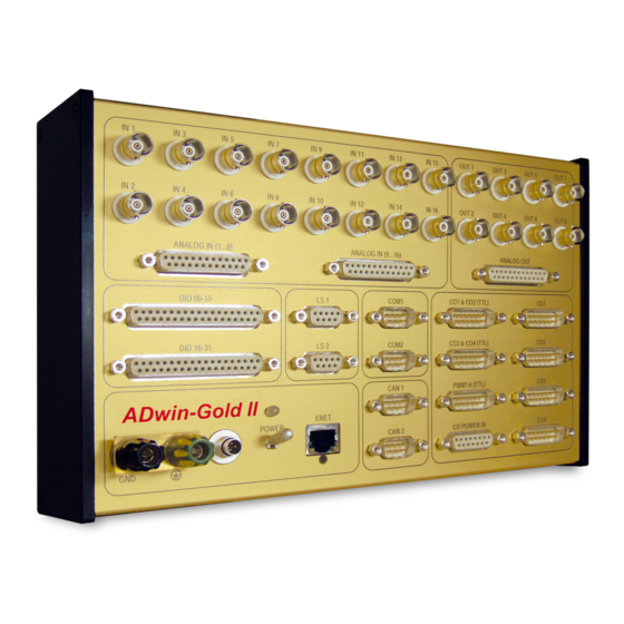
Page 16: Inputs And Outputs
ADwin-Gold II provides several pins with a voltage of +5V. The maximum current of 100mA applies to all pins together. The inputs and outputs of the ADwin-Gold II basic version is described on the following pages: – 16 analog inputs via 2 multiplexers (page –... -
Page 17: Analog Inputs And Outputs
The power supply from the power adapter at the computer also connects the earth of the ADwin-Gold II system with the earth of the computer. If you do not operate the PC and the ADwin-Gold II system in the same place, you should not use the power supplied by the PC but an external power supply unit which is earth-free, in order to avoid influ- ences by different ground reference potentials. - Page 18 Both instructions run with the 18-bit ADC, only return values have different resolution. Continuous conversion ADwin-Gold II provides a sequential control for each ADC, which can consecutively with sequential control read measurement values of several or all input channels of an ADC. Thus, the proces- sor can be discharged a lot and only has to read completely converted values from the sequential control’s buffer.
- Page 19 If it is not in the value range the maximum or minimum values are output. 5.1.3 Calculation Basis The voltage range of the ADwin-Gold II at the analog inputs and outputs is between Voltage range ˆ –10V to +10V ( bipolar 10V).
- Page 20 = -10V Gain factor k ADwin-Gold II has a programmable gain (PGA), which can amplify the input voltage by the factors 1, 2, 4, or 8. At the same time the measurement range gets smaller by the corresponding gain factor k (see Annex "Technical...
-
Page 21: Digital Inputs And Outputs
Do not use pins marked as "reserved". They are planned for changes and expansions and can cause damages to your system if you do not pay attention to this fact. The ADwin-Gold II is equipped with an external trigger input (EVENT) at pin 20 of the Trigger input (EVENT) D-SUB socket DIO 00-15 (see fig. -
Page 22: Watchdog
Fig. 11 – Overview of configurations with Conf_DIO Watchdog The correct operation of ADwin-Gold II can be controlled with a watchdog counter. If the watchdog counter is enabled, it decrements the counter value continuously. As soon as ADwin-Gold II , Manual February 2013... -
Page 23: Ls Bus
Watchdog_Status LS Bus ADwin-Gold II provides two interfaces for LS bus on 9-pin DSub connec- tors (female) LS1 and LS2; the pin assignment is shown on the right. The LS bus is a bi-directional serial bus with 5 MHz clock rate (Low Speed). - Page 24 Use the waiting times for instance for arithmetic operations and save CPU time: – The settling time of the multiplexer is 2µs (max.) at a maximum voltage jump of 20 Volt. – The conversion time of the ADC is 2µs. ADwin-Gold II , Manual February 2013...
-
Page 25: Add-On
SUB socket ANALOG OUT (see figure). Fig. 12 – Pin assignment ANALOG OUT of DA add-on You program the additional DACs like the DAC 1 and DAC 2 (see chapter 5.1 Programming chapter 15 starting from page 60). ADwin-Gold II , Manual February 2013... -
Page 26: Cnt Add-On
(external clock input) square-wave signals at the inputs A/CLK and B/DIR. A positive edge at CLR/LATCH either sets the counter to zero (CLR) or copies the counter values into the latch (LATCH). See also chapter 7.3. ADwin-Gold II , Manual February 2013... - Page 27 If you do not use a counter input, connect for safety reasons both lines of the (differential) input to a specified potential: Connect the positive input to +5V and the negative input to GND. ADwin-Gold II , Manual February 2013...
-
Page 28: Counter Software
(MSB) is interpreted as a sign, the highest positive number (2 -1) follows the highest negative number (-2 ) and the lowest positive number (0) follows the high- est negative number (-1). ADwin-Gold II , Manual February 2013... - Page 29 - i.e. the current counter value "laps" the last counter value which has been read out - is not registered. Such a lap overflow occurs after some 42 seconds with an input frequency of 100MHz. ADwin-Gold II , Manual February 2013...
-
Page 30: Using Event Counter
Rem Bit 4: set input CLR/LATCH as CLR input Rem Bit 5: enable input CLR/LATCH Cnt_Mode(1,100000b) Cnt_SE_Diff(0000b) 'all inputs single-ended Cnt_Enable(0001b) 'start counter 1 … Event: … Cnt_Latch(0001b) 'latch counter 1 = Cnt_Read_Latch(0001b) 'read latch value ADwin-Gold II , Manual February 2013... - Page 31 Rem Bit 4: set input CLR/LATCH as CLR input Rem Bit 5: enable input CLR/LATCH Cnt_Mode(1,100000b) Cnt_SE_Diff(1111b) 'all inputs differential Cnt_Enable(0001b) 'start counter 1 … Event: … Cnt_Latch(0001b) 'latch counter 1 = Cnt_Read_Latch(0001b) 'read latch value ADwin-Gold II , Manual February 2013...
-
Page 32: Using Pwm Counter
Copy register L2– to L3– Copy register L1– to L2– – Falling edge: • Copy counter value to L1– • If falling edge is set as reference edge: Copy register L2– to L3– Copy register L1– to L2– ADwin-Gold II , Manual February 2013... - Page 33 = 1 / T = 1 / (L2- − L3-) frequency / T = (L3- − L3+) / (L2+ − L3+) g = t / T = (L2- − L3+) / (L2- − L3-) duty cycle g = t ADwin-Gold II , Manual February 2013...
-
Page 34: Ssi Decoder
The functionality of the decoders is easily programmed with ADbasic instructions: Range Instructions Initialize decoder SSI_Mode SSI_Set_Bits SSI_Set_Clock read encoder data SSI_Read SSI_Start SSI_Status The instructions are in the include file <ADwinGoldII.INC>. More information can be found in the online help. ADwin-Gold II , Manual February 2013... -
Page 35: Pwm Outputs
Start PWM output PWM_Enable Set PWM mode PWM_Write_Latch Read PWM mode and status PWM_Get_Status PWM_Latch The instructions The instructions are in the include file <ADwinGoldII.INC>. More information can be found in the online help. ADwin-Gold II , Manual February 2013... -
Page 36: Can Add-On
The inputs of the CAN interfaces are located on the connectors CAN 1 and CAN 2. – 2 RSxxx interfaces (page Both interfaces can be configured separately per software to be operated as RS232 or RS485. The interface inputs are located on the connectors COM1 and COM2. ADwin-Gold II , Manual February 2013... -
Page 37: Can Interface
The message objects can either be configured to send or to receive messages. Message object 15 can only be used to receive messages. After initializing the CAN controller all message objects are not configured. ADwin-Gold II , Manual February 2013... - Page 38 0 and 1 are not compared, because they are set to zero in the global mask (= not rele- vant). Setting the bus frequency The CAN bus frequency depends on the configuration of the controller. ADwin-Gold II , Manual February 2013...
- Page 39 Read_Msg_Con Transmit Write / read access to the Set_Can_Reg controller register Get_Can_Reg The instructions are in the include file <ADwinGoldII.INC>. More information can also be found in the ADbasic manual and the online help. ADwin-Gold II , Manual February 2013...
-
Page 40: Rsxxx Interface
2.304MHz. Based on this fact, every Baud rate is possible that can be derived by an integer division of the basic frequency. The divisor can have values between 1...0FFFFh. The following table shows some common Baud rates and their divisors: ADwin-Gold II , Manual February 2013... - Page 41 R S485_ Send, Read_Fifo, Write_Fifo Write and read access Get_RS, Set_RS to the controller register The instructions are in the include file <ADwinGoldII.INC>. More information can be found starting from or the online help. ADwin-Gold II , Manual February 2013...
- Page 42 <= 1000) Then'Send data PAR_2 = Write_FIFO(1,DATA_1[PAR_1]) (PAR_2 = 0) Then PAR_1 EndIf PAR_3 = Read_FIFO(2) 'Read data (PAR_3 <> -1) Then DATA_2[PAR_4] = PAR_3 PAR_4 EndIf (PAR_4 > 1000) Then End'All data are transmitted ADwin-Gold II , Manual February 2013...
- Page 43 REM 1 stop bit, RS485 software handshake RS_Init(1,38400,0,8,0,3) RS_Init(2,38400,0,8,0,3) RS485_Send(1,1) 'Send interface 1 RS485_Send(2,0) 'Receive interface 2 Event: = Read_FIFO(2) 'Read data from interface 2 (val = 55) Then RS485_Send(2,1) 'Send interface 2 ret_val = Write_FIFO(2,44) 'Write data EndIf ADwin-Gold II , Manual February 2013...
-
Page 44: Profibus Add-On
The configuration tool loads all required information about the new slave from the appropriate GSD file; the file content is determined by EN 50170. After- wards, the slave can be accessed by any master. ADwin-Gold II , Manual February 2013... - Page 45 = Init_Profibus(2, 2, 1, 3, 1, conf_Arr, Data_1) To configure the slave correctly in the configuration tool you have to set the 2 outputs first and the 3 inputs afterwards (1 byte each). The graphic below shows this example configuration: ADwin-Gold II , Manual February 2013...
- Page 46 Clear The inputs are updated and the outputs are set to zero. Stop The slave is no longer part of the bus communication. Fig. 25 – Profibus: Operating modes ADwin-Gold II , Manual February 2013...
-
Page 47: Devicenet Add-On
Please note, that the terms "input" and "output" may have reverse meanings in ADbasic (slave) and in the configuration tool (master). Also, the order of setting inputs and out- puts may be of importance in the configuration tool. ADwin-Gold II , Manual February 2013... - Page 48 Initialization must be run with low priority since it takes some seconds; if it were a pro- cess with high priority, the PC interrupts the communication after a time (time-out). For the same reason, reading and writing data should be run with low priority. ADwin-Gold II , Manual February 2013...
-
Page 49: Ethercat Add-On
You are projecting the EtherCAT bus with a configuration tool suitable for the bus mas- ter. The following process description uses the program "TwinCAT System Manager" of the Beckhoff company as EtherCAT bus master. ADwin-Gold II , Manual February 2013... - Page 50 Load PDO Info from the device. Afterwards the slave configuration could be as shown as below: 2 ranges of 4 byte as inputs and 2 ranges of 4 byte as outputs. ADwin-Gold II , Manual February 2013...
- Page 51 EtherCAT Technology Group Ostendstraße 196 D-90482 Nürnberg Tel.: +49 9115405620 Fax : +49 9115405629 http://www.ethercat.org/ The following table shows the operating modes, the EtherCAT node supports and its Operating modes of behavior: EtherCAT node ADwin-Gold II , Manual February 2013...
- Page 52 The interface is part of the data exchange, inputs and outputs are not active. SafeOp The interface can receive data, outputs are not active. The interface is completely ready; inputs and outputs are active. Fig. 28 – EtherCAT: Operating modes ADwin-Gold II , Manual February 2013...
-
Page 53: Storage-16 Add-On
The clock is battery-backed (type CR1632) and can remain up to 2 years with- out any external power supply i.e. when the system is turned off. To replace the buffer battery send ADwin-Gold II to the address on the inner side of the cover page. -
Page 54: Adwin-Gold Ii-Boot
ADwin-Gold II-Boot starts a previously programmed application automatically after power-up. After installation of this application an operation without computer is possi- ble. With ADwin-Gold II-Boot the following steps are executed after power-up: – Loading the operating system – Loading of the compiled processes, compiled by ADbasic (max. 10). -
Page 55: Accessories
– cable connector for an external power supply – mounting kits for enclosures On the secondary side ADwin-Gold II-pow provides 12 Volt at a maximum load of 2 ADwin-Gold II-pow Ampere. The power supply unit is rated for the highest load and maximum expansions of the ADwin-Gold II. -
Page 56: Software
– Instructions for LS bus modules like HSM24V are described in a separate man- ual or in the online help. The TiCo processor of the ADwin-Gold II system can also access the inputs, outputs, and interfaces. The description of ADbasic instructions for T11 are therefore also valid for TiCoBasic. -
Page 57: System Functions
This section describes the following instructions: – Event_Config (page – Event_Enable (page – Set_LED (page – Watchdog_Init (page – Watchdog_Reset (page – Watchdog_Standby_Value (page – Watchdog_Status (page This section contains instructions für system functions of ADwin-Gold II. ADwin-Gold II , Manual February 2013... - Page 58 Example Rem Select the appropriate include file for ADbasic / TiCoBasic #INCLUDE ADwinGoldII.inc / GoldIITiCo.inc Init: Rem Configure event input for Rem minimum time 15 ns, neg. edge, event signal after 4 edges Event_Config(0,2,4) ADwin-Gold II , Manual February 2013...
- Page 59 Event_Enable En_CAN_Interrupt used in parallel, because both instructions set the used event source. See also Event_Config, En_CAN_Interrupt Valid for Gold II Example #INCLUDE ADwinGoldII.inc Init: Rem Set CAN interface 2 as event source Event_Enable(00010b) ADwin-Gold II , Manual February 2013...
- Page 60 Valid for Gold II Example Rem Select the appropriate include file for ADbasic / TiCoBasic #INCLUDE ADwinGoldII.inc / GoldIITiCo.inc Init: Stop_Process(15) Set_LED(1) 'set green LED Event: Rem … Finish: Set_LED(0) 'switch off LED Start_Process(15) ADwin-Gold II , Manual February 2013...
- Page 61 Watchdog_Reset, Watchdog_Standby_Value, Watchdog_Status Valid for Gold II Example Rem Select the appropriate include file for ADbasic / TiCoBasic #INCLUDE ADwinGoldII.inc / GoldIITiCo.inc Init: Watchdog_Init(1,0FFFEh,1111b)'enable and configure watchdog Event: Watchdog_Reset() 'reset watchdog regularly Rem … ADwin-Gold II , Manual February 2013...
- Page 62 Valid for Gold II Example Rem Select the appropriate include file for ADbasic / TiCoBasic #INCLUDE ADwinGoldII.inc / GoldIITiCo.inc Init: Watchdog_Init(1,0FFFEh,1111b)'enable and configure watchdog Event: Watchdog_Reset() 'reset watchdog regularly Rem … Finish: Watchdog_Init(0,0,0) 'disable watchdog ADwin-Gold II , Manual February 2013...
- Page 63 Gold II Example Rem Select the appropriate include file for ADbasic / TiCoBasic #INCLUDE ADwinGoldII.inc / GoldIITiCo.inc Init: Watchdog_Init(1,0FFFEh,0001b)'enable and configure watchdog Watchdog_Standby_Value(1)'set watchdog value to level high Event: Watchdog_Reset() 'reset watchdog regularly Rem … ADwin-Gold II , Manual February 2013...
- Page 64 Watchdog_Init. If the watchdog counter is disabled (bit 0 = 0), bit 1 has no function. See also Watchdog_Init, Watchdog_Reset, Watchdog_Standby_Value Valid for Gold II Example - / - ADwin-Gold II , Manual February 2013...
-
Page 65: Analog Inputs And Outputs
Set_Mux2 (page – Start_Conv (page – Wait_EOC (page – Seq_Mode (page – Seq_Read (page – Seq_Read8 (page – Seq_Read16 (page – Seq_Set_Delay (page – Seq_Set_Gain (page – Seq_Select (page – Seq_Start (page – Seq_Status (page ADwin-Gold II , Manual February 2013... - Page 66 ADwinGoldII.inc / GoldIITiCo.inc Rem Digital P-controller set_to, gain, diff, As Long 'Declaration Event: set_to Par_1 'Setpoint gain Par_2 'Dimension diff set_to ADC(1)'Calculate control deviation diff gain 'Calculate actuating value DAC(1, Out) 'Output of the actuating value ADwin-Gold II , Manual February 2013...
- Page 67 As Long Init: Processdelay 10000 Write_DAC(1,i) 'Set output register DAC1 Write_DAC(2,65535-i) 'Set output register DAC2 Event: Start_DAC() 'Start ouput of all DAC Write_DAC(1,i) 'Set output register DAC1 Write_DAC(2,65535-i) 'Set output register DAC2 Inc(i) (i=65535) Then ADwin-Gold II , Manual February 2013...
- Page 68 'Set output register DAC4 Event: Start_DAC() 'Start ouput of all DAC Write_DAC(1,Data_1[i]) 'Set output register DAC1 Write_DAC(2,Data_2[i]) 'Set output register DAC2 Write_DAC(3,Data_3[i]) 'Set output register DAC3 Write_DAC(4,Data_4[i]) 'Set output register DAC4 Inc(i) (i>1000) Then ADwin-Gold II , Manual February 2013...
- Page 69 ⋅ ---------------------------------------------- Voltage Digits 32768 – bipolar 65536 The measurement range is 20 Volt here (input voltage range: - 10V…10V). See also ADC24, Read_ADC, Set_Mux1, Set_Mux2, Start_Conv, Wait_EOC Valid for Gold II ADwin-Gold II , Manual February 2013...
- Page 70 Rem Please select the appropriate include for ADbasic / TiCoBasic #Include ADwinGoldII.inc 'for ADbasic Rem #Include GoldIITiCo.inc 'for TiCoBasic As Long 'Declaration Event: 'Measure analog input = ADC(1) 'Write measurement value into global variable, so 'that the computer can read it Par_1 ADwin-Gold II , Manual February 2013...
- Page 71 ⋅ ---------------------------------------------- Voltage Digits 8388608 – bipolar 16777216 The measurement range is 20 Volt here (input voltage range: - 10V…10V). See also ADC, Read_ADC24, Set_Mux1, Set_Mux2, Start_Conv, Wait_EOC Valid for Gold II ADwin-Gold II , Manual February 2013...
- Page 72 TiCoBasic #Include ADwinGoldII.inc 'for ADbasic Rem #Include GoldIITiCo.inc 'for TiCoBasic As Long 'Declaration Event: 'Measure analog input 1 = ADC24(1) 'Write measurement value into global variable so that 'the computer can read it. Par_1 ADwin-Gold II , Manual February 2013...
- Page 73 Rem use waiting time, except for access to IOs or external memory Rem … Start_Conv(11b) 'Start conversion for both ADCs Wait_EOC(11b) 'Wait for end of conversion Par_1 = Read_ADC(1) 'Read value of ADC1 Par_2 = Read_ADC(2) 'Read value of ADC2 ADwin-Gold II , Manual February 2013...
- Page 74 Rem use waiting time, except for access to IOs or external memory Rem … Start_Conv(11b) 'Start conversion for both ADCs Wait_EOC(11b) 'Wait for end of conversion val1 = Read_ADC24(1) 'Read value of ADC1 val2 = Read_ADC24(2) 'Read value of ADC2 ADwin-Gold II , Manual February 2013...
- Page 75 See also ADC, ADC24, Read_ADC, Read_ADC24, Set_Mux2, Start_Conv, Wait_EOC Valid for Gold II ADwin-Gold II , Manual February 2013...
- Page 76 Rem interrupt IO access for MUX settling time IO_Sleep(200) Rem use waiting time, except for access to IOs or external memory Rem … Start_Conv(1) 'Start AD-conversion ADC1 Wait_EOC(1) 'Wait for end of conversion of 'ADC1 = Read_ADC(1) 'Read value of ADC1 ADwin-Gold II , Manual February 2013...
- Page 77 See also ADC, ADC24, Read_ADC, Read_ADC24, Set_Mux1, Start_Conv, Wait_EOC Valid for Gold II ADwin-Gold II , Manual February 2013...
- Page 78 Rem interrupt IO access for MUX settling time IO_Sleep(200) Rem use waiting time, except for access to IOs or external memory Rem … Start_Conv(2) 'Start AD-conversion ADC2 Wait_EOC(2) 'Wait for end of conversion of 'ADC2 = Read_ADC(2) 'Read value of ADC2 ADwin-Gold II , Manual February 2013...
- Page 79 Rem use waiting time, except for access to IOs or external memory Rem … Start_Conv(1) 'Start ADC1 A/D-conversion Wait_EOC(1) 'Wait for end of conversion val1 = Read_ADC(1) 'Read out value Multiplexer settling time and conversion time are given on page ADwin-Gold II , Manual February 2013...
- Page 80 'Start A/D-conversion ADC2 Wait_EOC(10b) 'Wait for end of conversion at ''ADC2 = Read_ADC(2) 'Read out value Multiplexer settling time and conversion time are given on page The conversion time of the ADC is 2µs. ADwin-Gold II , Manual February 2013...
- Page 81 The conversion is started with Seq_Start. Inside a process cycle just reads the newest mea- Seq_Read surement value. See also ADC, Seq_Read, Seq_Read8, Seq_Read16, Seq_Set_Delay, Seq_ Set_Gain, Seq_Select, Seq_Start, Seq_Status Valid for Gold II ADwin-Gold II , Manual February 2013...
- Page 82 Rem sequential control 2 = even numbered channels. Seq_Select(0FFFFh) Rem start sequential control of ADC2 Seq_Start(10b) Event: Rem read current values of even channels Step Data_1[i] = Seq_Read(i) Next Finish: Seq_Mode(2,0) 'reset to standard mode ADwin-Gold II , Manual February 2013...
- Page 83 Rem sequential control 2 = even numbered channels. Seq_Select(0FFFFh) Rem start sequential control of ADC2 Seq_Start(10b) Event: Rem read current values of even channels Step Data_1[i] = Seq_Read(i) Next Finish: Seq_Mode(2,0) 'reset to standard mode ADwin-Gold II , Manual February 2013...
- Page 84 Seq_Set_Gain(2,0)'gain factor 1 Seq_Select(0FFh) 'select channels 1…8 Rem start sequential control of ADC1 and ADC2 Seq_Start(11b) Event: Rem read values of channels 1…8 Seq_Read8(Data_1,1) Finish: Seq_Mode(1,0) 'reset to standard mode Seq_Mode(2,0) 'reset to standard mode ADwin-Gold II , Manual February 2013...
- Page 85 Seq_Set_Gain(2,0)'gain factor 1 Seq_Select(0FFFFh) 'select channels 1…16 Rem start sequential control of ADC1 and ADC2 Seq_Start(11b) Event: Rem read values of channels 1…16 Seq_Read16(Data_1,1) Finish: Seq_Mode(1,0) 'reset to standard mode Seq_Mode(2,0) 'reset to standard mode ADwin-Gold II , Manual February 2013...
- Page 86 The waiting time is calculated according to the following formula: ⋅ waiting time 20ns conversion time mux_time The conversion time of the ADC is 2µs. See also Seq_Mode, Seq_Read, Seq_Read8, Seq_Read16, Seq_Set_Gain, Seq_Select, Seq_Start, Seq_Status Valid for Gold II ADwin-Gold II , Manual February 2013...
- Page 87 Rem sequential control 2 = even numbered channels. Seq_Select(0FFFFh) Rem start sequential control of ADC2 Seq_Start(10b) Event: Rem read current values of even channels Step Data_1[i] = Seq_Read(i) Next Finish: Seq_Mode(2,0) 'reset to standard mode ADwin-Gold II , Manual February 2013...
- Page 88 Rem sequential control 2 = even numbered channels. Seq_Select(0FFFFh) Rem start sequential control of ADC2 Seq_Start(10b) Event: Rem read current values of even channels Step Data_1[i] = Seq_Read(i) Next Finish: Seq_Mode(2,0) 'reset to standard mode ADwin-Gold II , Manual February 2013...
- Page 89 The channels are automatically sorted in ascending order of channel numbers, that is the sequential controls convert the channel with the smallest number first. See also Seq_Mode, Seq_Read, Seq_Read8, Seq_Read16, Seq_Set_Delay, Seq_Set_Gain, Seq_Start, Seq_Status Valid for Gold II ADwin-Gold II , Manual February 2013...
- Page 90 Rem sequential control 2 = even numbered channels. Seq_Select(0FFFFh) Rem start sequential control of ADC2 Seq_Start(10b) Event: Rem read current values of even channels Step Data_1[i] = Seq_Read(i) Next Finish: Seq_Mode(2,0) 'reset to standard mode ADwin-Gold II , Manual February 2013...
- Page 91 Rem control 1 and channels 2,4,6 for seq. control 2 Seq_Select(07Fh) Rem start both sequential controls Seq_Start(11b) Event: Rem read current values of channels 1..8 Seq_Read8(Data_1,i) : > 1600) Then Finish: Seq_Mode(1,0) 'reset to standard mode Seq_Mode(2,0) 'reset to standard mode ADwin-Gold II , Manual February 2013...
- Page 92 Rem start sequential control of ADC1 Seq_Start(01b) Event: Until (Seq_Status(1)=0) Rem read values of odd channels Step Data_1[i] = Seq_Read(i) Next Rem start sequential control of ADC1 Seq_Start(01b) Finish: Seq_Mode(2,0) 'reset to standard mode ADwin-Gold II , Manual February 2013...
-
Page 93: Digital Inputs And Outputs
Digout_Bits (page 101) – Digout_Long (page 102) – Digout_Reset (page 103) – Digout_Set (page 104) – Digout_Word1 (page 105) – Digout_Word2 (page 106) – Get_Digout_Long (page 107) – Get_Digout_Word1 (page 108) – Get_Digout_Word2 (page 109) ADwin-Gold II , Manual February 2013... - Page 94 Digout_Long, Digout_Word1, Digout_Word2, Get_Digout_Long, Get_ Digout_Word1, Get_Digout_Word2 Valid for Gold II Example Rem Please select the appropriate include for ADbasic / TiCoBasic #Include ADwinGoldII.inc / GoldIITiCo.inc Init: 'Configure DIO00…DIO15 as inputs 'and DIO16…DIO31 as outputs Conf_DIO(1100b) ADwin-Gold II , Manual February 2013...
- Page 95 ADwinGoldII.inc / GoldIITiCo.inc Init: Conf_DIO(1100b) 'channels 0:15 as inputs Event: Rem input DIO00 = high? (Digin(0) = 1) Then Rem Set DIO18 and DIO20 to values of DIO02 and DIO05 Digout(18, Digin(2)) Digout(20, Digin(5)) EndIf ADwin-Gold II , Manual February 2013...
- Page 96 #Include ADwinGoldII.inc / GoldIITiCo.inc Init: Conf_DIO(1100b) 'channels 0:15 as inputs Event: Rem check positive and negative edges, mask out outputs Par_1 = Digin_Edge(1) Par_2 = Digin_Edge(0) Rem output edge changes If (Par_1+Par_2>0)Then Digout_Bits(Shift_Left(Par_1,16),Shift_Left(Par_2,16)) EndIf ADwin-Gold II , Manual February 2013...
- Page 97 'edge control off Digin_FIFO_Clear() 'clear FIFO Digin_FIFO_Enable(10011b)'control channels 1,2,5 index Event: = Digin_FIFO_Full() 'number of value pairs (num > 0) Then (index+num > 10000) Then index Rem read value pairs Digin_FIFO_Read(Data_1[index], Data_2[index]) index index+1 Next EndIf ADwin-Gold II , Manual February 2013...
- Page 98 If and as long as the FIFO array is filled completely, any additional value pair cannot be saved and will thus be lost. See also Digin_FIFO_Clear, Digin_FIFO_Full, Digin_FIFO_Read, Digin_FIFO_ Read_Timer, Digin_Edge, Conf_DIO Valid for Gold II ADwin-Gold II , Manual February 2013...
- Page 99 'edge control off Digin_FIFO_Clear() 'clear FIFO Digin_FIFO_Enable(10011b)'control channels 1,2,5 index Event: = Digin_FIFO_Full() 'number of value pairs (num > 0) Then (index+num > 10000) Then index Rem read value pairs Digin_FIFO_Read(Data_1[index], Data_2[index]) index index+1 Next EndIf ADwin-Gold II , Manual February 2013...
- Page 100 'edge control off Digin_FIFO_Clear() 'clear FIFO Digin_FIFO_Enable(10011b)'control channels 1,2,5 index Event: = Digin_FIFO_Full() 'number of value pairs (num > 0) Then (index+num > 10000) Then index Rem read value pairs Digin_FIFO_Read(Data_1[index], Data_2[index]) index index+1 Next EndIf ADwin-Gold II , Manual February 2013...
- Page 101 As Long Init: Conf_DIO(1100b) 'channels 0:15 as inputs Digin_FIFO_Enable(0) 'edge control off Digin_FIFO_Clear() 'clear FIFO Digin_FIFO_Enable(10011b)'control channels 1,2,5 index Event: (Digin_FIFO_Full()>0) Then Rem read one value pair Digin_FIFO_Read(Data_1[index], Data_2[index]) index index (index>10000) Then index EndIf ADwin-Gold II , Manual February 2013...
- Page 102 Rem Please select the appropriate include for ADbasic / TiCoBasic #Include ADwinGoldII.inc / GoldIITiCo.inc start, diff, count As Long Init: count start = Digin_FIFO_Read_Timer() Event: Rem count number of counter overflows (Digin_FIFO_Read_Timer() < start) Then Inc(count) start = Digin_FIFO_Read_Timer() EndIf ADwin-Gold II , Manual February 2013...
- Page 103 ADwinGoldII.inc / GoldIITiCo.inc Data_1[10000] As Long As FIFO Init: Rem Configure all channels As inputs Conf_DIO(0000b) Event: Rem Is digital input DIO17 set? ((Shift_Right(Digin_Long(),17) 1) = 1) Then Data_1 = ADC(1) 'get measurement value EndIf ADwin-Gold II , Manual February 2013...
- Page 104 As Long As FIFO Init: REM Configure inputs and outputs Conf_DIO(1100b) Event: REM query if inputs DIO01 and DIO02 are level High ((Digin_Word1() 110b) = 110b) Then Data_1 = ADC(1) 'get measurement value EndIf ADwin-Gold II , Manual February 2013...
- Page 105 As Long As FIFO Init: REM Configure inputs and outputs Conf_DIO(0011b) Event: REM query if inputs DIO16 and DIO17 are level High ((Digin_Word2() 11b) = 11b) Then Data_1 = ADC(1) 'get measurement value EndIf ADwin-Gold II , Manual February 2013...
- Page 106 Init: REM Configure inputs and outputs Conf_DIO(1100b) Event: value = ADC(1) 'get measurement value (value > 1600) Then'limit exceeded? Digout(19,1) 'set output DIO19 to level high Digout(23,0) 'set output DIO23 to level low EndIf ADwin-Gold II , Manual February 2013...
- Page 107 Event: value = ADC(1) 'get measurement value (value > 3000) Then'limit exceeded? Rem Set outputs DIO00 and DIO02 to level high, Rem set outputs DIO001, DIO003 and DIO004 to level low. Digout_Bits(00101b, 11010b) EndIf ADwin-Gold II , Manual February 2013...
- Page 108 REM Configure all channels as outputs Conf_DIO(1111b) Event: value = ADC(1) 'get measurement value (value > 1500) Then 'limit exceeded? Rem Set outputs DIO00, DIO02, DIO06 to level high, Rem all other channels to level low. Digout_Long(1000101b) EndIf ADwin-Gold II , Manual February 2013...
- Page 109 As Long Init: REM configure inputs/outputs CONF_DIO(0011b) Processdelay 10000 Event: value = ADC(1) 'get measurement value (value > 3000) Then'limit exceeded? REM set outputs DIO01, DIO03, and DIO04 to level Low Digout_Reset(11010b) EndIf ADwin-Gold II , Manual February 2013...
- Page 110 ADwinGoldII.inc / GoldIITiCo.inc value As Long Init: REM configure inputs/outputs CONF_DIO(0011b) Processdelay 10000 Event: value = ADC(1) 'get measurement value (value > 3000) Then'limit exceeded? REM set outputs DIO00 and DIO02 to level High Digout_Set(00101b) EndIf ADwin-Gold II , Manual February 2013...
- Page 111 REM Configure inputs and outputs Conf_DIO(0011b) Event: value = ADC(1) 'get measurement value (value > 3000) Then 'limit exceeded? Rem Set outputs DIO00, DIO02 to level high, Rem all other channels to level low. Digout_Word1(101b) EndIf ADwin-Gold II , Manual February 2013...
- Page 112 REM Configure inputs and outputs Conf_DIO(1100b) Event: value = ADC(1) 'get measurement value (value > 2500) Then 'limit exceeded? Rem Set outputs DIO17, DIO20 to level high, Rem all other channels to level low. Digout_Word2(10010b) EndIf ADwin-Gold II , Manual February 2013...
- Page 113 Gold II Example Rem Please select the appropriate include for ADbasic / TiCoBasic #Include ADwinGoldII.inc / GoldIITiCo.inc Init: REM Configure all channels as outputs Conf_DIO(1111b) Event: Par_1 = Get_Digout_Long() 'read back bits 31:00 from register ADwin-Gold II , Manual February 2013...
- Page 114 Gold II Example Rem Please select the appropriate include for ADbasic / TiCoBasic #Include ADwinGoldII.inc / GoldIITiCo.inc Init: REM Configure inputs and outputs Conf_DIO(0011b) Event: Par_1 = Get_Digout_Word1() 'read back bits 15:00 from register ADwin-Gold II , Manual February 2013...
- Page 115 Gold II Example Rem Please select the appropriate include for ADbasic / TiCoBasic #Include ADwinGoldII.inc / GoldIITiCo.inc Init: REM Configure inputs and outputs Conf_DIO(1100b) Event: Par_1 = Get_Digout_Word2() 'read back bits 31:16 from register ADwin-Gold II , Manual February 2013...
-
Page 116: Counters
ADwin Counters 15.4 Counters This section describes instructions to access counter inputs of ADwin-Gold II: – Cnt_Clear (page 111) – Cnt_Enable (page 113) – Cnt_Get_Status (page 114) – Cnt_Get_PW (page 115) – Cnt_Get_PW_HL (page 116) – Cnt_Latch (page 117) –... - Page 117 Else, with bit 1=1, the counter inputs A, B have also to be set to TTL level high, in order to clear the counter. See also Cnt_Enable, Cnt_Get_Status, Cnt_Get_PW, Cnt_Get_PW_HL, Cnt_ Latch, Cnt_Mode, Cnt_PW_Latch, Cnt_Read, Cnt_Read_Latch, Cnt_ SE_Diff Valid for Gold II-CNT ADwin-Gold II , Manual February 2013...
- Page 118 Cnt_Read_Latch(1)'read latch A of counter 1 and new_2 Cnt_Read_Latch(2)' latch A of counter 2. Par_1 new_1 old_1 'caluclate the difference (f = 'impulses/time) Par_2 new_2 old_2 ' -"- old_1 new_1 'Save new counter values old_2 new_2 ' -"- ADwin-Gold II , Manual February 2013...
- Page 119 Cnt_Read_Latch(1)'read latch A of counter 1 and new_2 Cnt_Read_Latch(2)' latch A of counter 2. Par_1 new_1 old_1 'caluclate the difference (f = 'impulses/time) Par_2 new_2 old_2 ' -"- old_1 new_1 'Save new counter values old_2 new_2 ' -"- ADwin-Gold II , Manual February 2013...
- Page 120 0. The status register is automatically reset by reading. See also Cnt_Clear, Cnt_Enable, Cnt_Get_PW, Cnt_Get_PW_HL, Cnt_Latch, Cnt_Mode, Cnt_PW_Latch, Cnt_Read, Cnt_Read_Latch, Cnt_SE_Diff Valid for Gold II-CNT Example - / - ADwin-Gold II , Manual February 2013...
- Page 121 'all counters single ended (TTL) Cnt_Mode(1,0) 'Counter 1: PWM at input A Cnt_Mode(2,0) 'Counter 2: PWM at input A Cnt_Enable(1100000000b) 'start PWM counters 1+2 Event: Cnt_PW_Latch(11b) 'latch both counters 1+2 Cnt_Get_PW_HL(1,Par_1,Par_2) 'read high/low time Cnt_Get_PW(1,FPar_1,FPar_2) 'read frequency./duty cycle ADwin-Gold II , Manual February 2013...
- Page 122 'all counters single ended (TTL) Cnt_Mode(1,0) 'Counter 1: PWM at input A Cnt_Mode(2,0) 'Counter 2: PWM at input A Cnt_Enable(1100000000b) 'start PWM counters 1+2 Event: Cnt_PW_Latch(11b) 'latch both counters 1+2 Cnt_Get_PW_HL(1,Par_1,Par_2) 'read high/low time Cnt_Get_PW(1,FPar_1,FPar_2) 'read frequency./duty cycle ADwin-Gold II , Manual February 2013...
- Page 123 Cnt_Latch set to 0 (zero). Latch A is read out into a variable with command. Cnt_Read_Latch Valid for Gold II-CNT See also Cnt_Clear, Cnt_Enable, Cnt_Get_Status, Cnt_Get_PW, Cnt_Get_PW_ HL, Cnt_Mode, Cnt_PW_Latch, Cnt_Read, Cnt_Read_Latch, Cnt_SE_ Diff ADwin-Gold II , Manual February 2013...
- Page 124 Cnt_Read_Latch(1)'read latch A of counter 1 and new_2 Cnt_Read_Latch(2)' latch A of counter 2. Par_1 new_1 old_1 'caluclate the difference (f = 'impulses/time) Par_2 new_2 old_2 ' -"- old_1 new_1 'Save new counter values old_2 new_2 ' -"- ADwin-Gold II , Manual February 2013...
- Page 125 If you want to clear a counter with bit 1=0. El- Cnt_Clear pattern se, with bit 1=1, the counter inputs A, B have also to be set to TTL level high, in order to clear the counter. ADwin-Gold II , Manual February 2013...
- Page 126 Cnt_Read_Latch(1)'read latch A of counter 1 and new_2 Cnt_Read_Latch(2)' latch A of counter 2. Par_1 new_1 old_1 'caluclate the difference (f = 'impulses/time) Par_2 new_2 old_2 ' -"- old_1 new_1 'Save new counter values old_2 new_2 ' -"- ADwin-Gold II , Manual February 2013...
- Page 127 'all counters single ended (TTL) Cnt_Mode(1,0) 'Counter 1: PWM at input A Cnt_Mode(2,0) 'Counter 2: PWM at input A Cnt_Enable(1100000000b) 'start PWM counters 1+2 Event: Cnt_PW_Latch(11b) 'latch both counters 1+2 Cnt_Get_PW_HL(1,Par_1,Par_2) 'read high/low time Cnt_Get_PW(1,FPar_1,FPar_2) 'read frequency./duty cycle ADwin-Gold II , Manual February 2013...
- Page 128 Cnt_Read_Latch(1)'read latch A of counter 1 and new_2 Cnt_Read_Latch(2)' latch A of counter 2. Par_1 new_1 old_1 'caluclate the difference (f = 'impulses/time) Par_2 new_2 old_2 ' -"- old_1 new_1 'Save new counter values old_2 new_2 ' -"- ADwin-Gold II , Manual February 2013...
- Page 129 Shadow register for Latch 2, negative edges. Shadow register for Latch 3, negative edges. Shadow register for software latch, VR counter. Counter status. Notes - / - See also Cnt_Sync_Latch Valid for Gold II-CNT Example Cnt_Sync_Latch ADwin-Gold II , Manual February 2013...
- Page 130 Cnt_Read_Latch(1)'read latch A of counter 1 and new_2 Cnt_Read_Latch(2)' latch A of counter 2. Par_1 new_1 old_1 'caluclate the difference (f = 'impulses/time) Par_2 new_2 old_2 ' -"- old_1 new_1 'Save new counter values old_2 new_2 ' -"- ADwin-Gold II , Manual February 2013...
- Page 131 Bit no. in 31 … 4 pattern Inputs of counter – Notes After start-up, counter inputs are set to input mode single-ended. See also Cnt_Clear, Cnt_Enable, Cnt_Get_Status, Cnt_Latch, Cnt_Mode, Cnt_ Read, Cnt_Read_Latch Valid for Gold II-CNT ADwin-Gold II , Manual February 2013...
- Page 132 = 10000b) Then 'correlation error Par_4 'number correlation error up to 'now error 'set error flag EndIf Par_5 Shift_Right(Par_2 100b,2) 'status CLR input Par_6 Par_2 'status input A Par_7 Shift_Right(Par_2 10b,1) 'status input B ADwin-Gold II , Manual February 2013...
- Page 133 The instruction therefore has the same function as Cnt_Latch Cnt_PW_Latch gether. The buffers can be read e.g. with or Cnt_Get_PW. Cnt_Read_Latch See also Cnt_Get_PW, Cnt_Latch, Cnt_Mode, Cnt_Latch, Cnt_Read_Int_Regis- ter, Cnt_PW_Latch Valid for Gold II-CNT ADwin-Gold II , Manual February 2013...
- Page 134 'number of edges between events (edges <> 0) Then pw_cnt = Cnt_Read_Int_Register(1,8) 'positive edges latch 1 time pw_cnt oldpw 'calculate timebase frequency edges*100000000/time 'frequency '(100000000=timer frequency) oldcnt=newcnt 'store VR-counter value oldpw =newpw 'store PW-counter value EndIf ADwin-Gold II , Manual February 2013...
-
Page 135: Ssi Interface
ADwin SSI interface 15.5 SSI interface This section describes instructions to access SSI decoders of ADwin-Gold II: – SSI_Mode (page 130) – SSI_Read (page 131) – SSI_Set_Bits (page 132) – SSI_Set_Clock (page 133) – SSI_Start (page 134) – SSI_Status (page... - Page 136 'encoders 1+2) SSI_Set_Bits(1,10) '10 encoder bits for encoder 1 SSI_Set_Bits(2,25) '25 encoder bits for encoder 2 Event: Par_1 = SSI_Read(1) 'Read out position value '(encoder Par_2 = SSI_Read(2) 'Read out position value '(encoder 2) ADwin-Gold II , Manual February 2013...
- Page 137 REM Change value from Gray-code into a binary value: 'delete value of the last 'conversion ' -"- 'Check all 32 possible bits (Shift_Right(Par_1,(32 - n)) (Shift_Left(m,(32 - n))) Next Par_9 'The result of the Gray/binary 'conversion in Par_9 ADwin-Gold II , Manual February 2013...
- Page 138 'Set continuous-mode (encoders '1+2) SSI_Set_Bits(1,10) '10 encoder bits for encoder 1 SSI_Set_Bits(2,25) '25 encoder bits for encoder 2 Event: Par_1 = SSI_Read(1) 'Read out position value '(encoder Par_2 = SSI_Read(2) 'Read out position value '(encoder ADwin-Gold II , Manual February 2013...
- Page 139 '1+2 SSI_Set_Bits(1,10) '10 encoder bits for encoder 1 SSI_Set_Bits(2,22) '22 encoder bits for encoder 2 Event: Par_1 = SSI_Read(1) 'Read out position value '(encoder 1) Par_2 = SSI_Read(2) 'Read out position value '(encoder 2) ADwin-Gold II , Manual February 2013...
- Page 140 'completely, then … Par_1 = SSI_Read(1) 'read out and display position 'value 'For encoder 2: Until (SSI_Status(2) = 0) 'If position value is read 'completely, then … Par_2 = SSI_Read(2) 'read out and display position 'value ADwin-Gold II , Manual February 2013...
- Page 141 'read, then … Par_1 = SSI_Read(1) 'Read out and display position 'value 'For encoder 2: Until (SSI_Status(2) = 0) 'If position value is completely 'read, then … Par_3 = SSI_Read(2) 'Read out and display position 'value ADwin-Gold II , Manual February 2013...
-
Page 142: Pwm Outputs
ADwin PWM Outputs 15.6 PWM Outputs This section describes instructions to access PWM outputs of ADwin-Gold II: – PWM_Enable (page 137) – PWM_Get_Status (page 138) – PWM_Init (page 139) – PWM_Latch (page 141) – PWM_Reset (page 142) – PWM_Standby_Value (page 143) –... - Page 143 The time, when the PWM outputs are disabled–at once or after the next end of period–depends on the setting which was done with PWM_Init (parameter mode). See also PWM_Get_Status, PWM_Init, PWM_Latch, PWM_Reset, PWM_ Standby_Value, PWM_Write_Latch Valid for Gold II-CNT Example PWM_Init (page 139) ADwin-Gold II , Manual February 2013...
- Page 144 Bit = 1: PWM output is running. Bit no. 31…6 PWM output – Notes - / - See also PWM_Enable, PWM_Init, PWM_Latch, PWM_Reset, PWM_Standby_ Value, PWM_Write_Latch Valid for Gold II-CNT Example - / - ADwin-Gold II , Manual February 2013...
- Page 145 PWM outputs must be stopped with or disabled with PWM_Reset PWM_ in order to change defaults. Afterwards the PWM outputs are Enable enabled again. See also PWM_Enable, PWM_Get_Status, PWM_Latch, PWM_Reset, PWM_ Standby_Value, PWM_Write_Latch Valid for Gold II-CNT ADwin-Gold II , Manual February 2013...
- Page 146 As Long Init: freq1 1000 '1000 Hz freq2 2000 '2000 Hz '50 % '70 % PWM_Reset(011b) 'stop channels 1 und 2 channel PWM_Init(channel,0,0,0,0) Next PWM_Write_Latch(1,pw1,freq1) PWM_Write_Latch(2,pw2,freq2) PWM_Latch(11b) PWM_Enable(011b) 'start output Event: PWM_Write_Latch(1,pw1,freq1) PWM_Write_Latch(2,pw2,freq2) PWM_Latch(11b) ADwin-Gold II , Manual February 2013...
- Page 147 The time, when the output of the new values starts–at once or after the next end of period–depends on the setting which was done with PWM_ (parameter mode). Init See also PWM_Enable, PWM_Get_Status, PWM_Init, PWM_Reset, PWM_ Standby_Value, PWM_Write_Latch Valid for Gold II-CNT Example PWM_Init (page 139) ADwin-Gold II , Manual February 2013...
- Page 148 – Notes The output will be stopped immediately even when has set PWM_Init a different stop mode. See also PWM_Enable, PWM_Get_Status, PWM_Init, PWM_Latch, PWM_ Standby_Value, PWM_Write_Latch Valid for Gold II-CNT Example PWM_Init (page 139) ADwin-Gold II , Manual February 2013...
- Page 149 The default level will also be set after the PWM output has stopped. After power-up the outputs are set to TTL-level low. See also PWM_Enable, PWM_Get_Status, PWM_Init, PWM_Latch, PWM_Re- set, PWM_Write_Latch Valid for Gold II-CNT Example - / - ADwin-Gold II , Manual February 2013...
- Page 150 The highest output frequency where the duty cycle can be still defined in 1%-steps, is 500kHz. See also PWM_Enable, PWM_Get_Status, PWM_Init, PWM_Latch, PWM_Re- set, PWM_Standby_Value Valid for Gold II-CNT Example PWM_Init (page 139) ADwin-Gold II , Manual February 2013...
-
Page 151: Can Interface
ADwin CAN interface 15.7 CAN interface This section describes instructions to access CAN interfaces of ADwin-Gold II: – CAN_Msg (page 146) – En_CAN_Interrupt (page 148) – En_Receive (page 149) – En_Transmit (page 150) – Get_CAN_Reg (page 151) – Init_CAN (page 152) –... - Page 152 Enter the data bytes to be transferred and their number into the field CAN_Msg[], before transferring them with Transmit. See also En_CAN_Interrupt, En_Receive, En_Transmit, Get_CAN_Reg, Init_ CAN, Read_Msg, Set_CAN_Baudrate, Set_CAN_Reg, Transmit Valid for Gold II-CAN ADwin-Gold II , Manual February 2013...
- Page 153 REM divide bit pattern (32 Bit) into bytes CAN_Msg[4] = Par_1 0FFh 'assign LSB CAN_Msg[4-i] = Shift_Right(Par_1,8*i) 0FFh Next CAN_Msg[9] = 'message length in bytes Event: Transmit(1,6) 'Send message object 6 Receive a float value see example at Read_Msg ADwin-Gold II , Manual February 2013...
- Page 154 Init: Init_CAN(1) 'Initialize CAN controller 1 En_Receive(1,1,200,0) 'Initialize message object 1 of 'controller 1 'to receive CAN messages with 'identifier 200 En_CAN_Interrupt(1,1) 'Enable triggering of interrupts '(ext. EVENT) when receiving the 'message object 1 ADwin-Gold II , Manual February 2013...
- Page 155 Gold II-CAN Example Rem Please select the appropriate include for ADbasic / TiCoBasic #Include ADwinGoldII.inc / GoldIITiCo.inc Init: Init_CAN(1) 'Initialization CAN controller 1 En_Receive(1,1,200,0) 'Initialize message object 1 to 'receive CAN messages with 'identifier 200 ADwin-Gold II , Manual February 2013...
- Page 156 #Include ADwinGoldII.inc / GoldIITiCo.inc Init: Init_CAN(1) 'Initialize CAN-Controller 1 Rem Initialize message objects of interface 1: Rem Object 2 for receive with identifier 200, Rem Object 6 for sending with identifier 40 En_Receive(1,1,200,0) En_Transmit(1,6,40,0) ADwin-Gold II , Manual February 2013...
- Page 157 See also Set_CAN_Baudrate, Set_CAN_Reg Valid for Gold II-CAN Example Rem Please select the appropriate include for ADbasic / TiCoBasic #Include ADwinGoldII.inc / GoldIITiCo.inc Init: Init_CAN(1) 'Initialize CAN controller 1 Par_1 Get_CAN_Reg(1,0)'Read out control register ADwin-Gold II , Manual February 2013...
- Page 158 See also CAN_Msg, En_Receive, En_Transmit, Get_CAN_Reg Valid for Gold II-CAN Example Rem Please select the appropriate include for ADbasic / TiCoBasic #Include ADwinGoldII.inc / GoldIITiCo.inc Init: Init_CAN(1) 'Initialize CAN controller 1 on 'CAN module 1 ADwin-Gold II , Manual February 2013...
- Page 159 As often as needed: Check for a received message and save to CAN_Msg with Read_Msg. You can read a received message only once. See also CAN_Msg, En_Receive, En_Transmit, Get_CAN_Reg, Read_Msg_ Valid for Gold II-CAN ADwin-Gold II , Manual February 2013...
- Page 160 = Shift_Left(Par_1,8) + CAN_Msg[n]'a 32-bit value Next REM Convert the bit pattern in Par_1 to data type FLOAT and assign to the variable FPar_1. FPar_1 = Cast_LongToFloat(Par_1) EndIf Sending a float value see example at Transmit. ADwin-Gold II , Manual February 2013...
- Page 161 • Check for a new message, and if, store the message in CAN_Msg with Read_Msg. You can read a received message only once. See also CAN_Msg, En_CAN_Interrupt, En_Receive, En_Transmit, Read_Msg Valid for Gold II-CAN ADwin-Gold II , Manual February 2013...
- Page 162 CAN_Msg[n]'a 32-bit value Next REM Convert the bit pattern in Par_1 to data type FLOAT and REM assign to the variable FPar_1. FPar_1 = Cast_LongToFloat(Par_1) EndIf Sending a float value see example at Transmit. ADwin-Gold II , Manual February 2013...
- Page 163 Get_CAN_Reg, Set_CAN_Reg Valid for Gold II-CAN Example Rem Please select the appropriate include for ADbasic / TiCoBasic #Include ADwinGoldII.inc / GoldIITiCo.inc Init: Init_CAN(1) 'Initialize CAN controller 1 Par_1 Set_CAN_Baudrate(1,125000)'Set Baud rate to 125 'kBit/s ADwin-Gold II , Manual February 2013...
- Page 164 Get_CAN_Reg Valid for Gold II-CAN Example Rem Please select the appropriate include for ADbasic / TiCoBasic #Include ADwinGoldII.inc / GoldIITiCo.inc Init: Init_CAN(1) 'Initialize CAN controller 1 Set_CAN_Reg(1,0,1) 'Set control register to the 'value 1 ADwin-Gold II , Manual February 2013...
- Page 165 REM divide bit pattern (32 Bit) into 4 bytes CAN_Msg[4] = Par_1 0FFh 'assign LSB CAN_Msg[4-i] = Shift_Right(Par_1,8*i) 0FFh Next CAN_Msg[9] = 'message length in bytes Event: Transmit(2,6) 'Send message object 6 Receiving a float value see example at Read_Msg. ADwin-Gold II , Manual February 2013...
-
Page 166: Rsxxx Interface
This section describes instructions to access RSxxx interfaces of ADwin-Gold – Check_Shift_Reg (page 161) – Get_RS (page 162) – Read_FIFO (page 163) – RS485_Send (page 164) – RS_Init (page 165) – RS_Reset (page 167) – Set_RS (page 168) – Write_FIFO (page 169) ADwin-Gold II , Manual February 2013... - Page 167 Gold II-CAN Example Rem Please select the appropriate include for ADbasic / TiCoBasic #Include ADwinGoldII.inc / GoldIITiCo.inc Event: Rem … Rem check if RSxxx interface still has data to send Par_1 = Check_Shift_Reg(1) Rem … ADwin-Gold II , Manual February 2013...
- Page 168 (data-sheet of the manufacturer Texas Instruments). For more common applications more comfortable instructions are availabe in the include file. See also Check_Shift_Reg, RS_Init, RS_Reset, Set_RS Valid for Gold II-CAN Example - / - ADwin-Gold II , Manual February 2013...
- Page 169 'interface 1 'with 9600 Baud, without parity, '8 data bits, 1 stop bit and 'hardware handshake. Event: Par_1 = Read_FIFO(1) 'Get a value from the FIFO. If 'the FIFO is empty, -1 is 'returned. ADwin-Gold II , Manual February 2013...
- Page 170 Sender/receiver: The RSxxx interface can transfer data to the bus and back at the same time. Thus, the sent data can be checked. See also Check_Shift_Reg, Get_RS, RS_Init, RS_Reset, Set_RS Valid for Gold II-CAN Example - / - ADwin-Gold II , Manual February 2013...
- Page 171 If transfer protocol RS485 is set, the transfer direction must be set, too (with RS485_Send). You find a list of standard baud rates on page 35 (fig. 23). See also Check_Shift_Reg, Get_RS, RS485_Send, RS_Reset, Set_RS Valid for Gold II-CAN ADwin-Gold II , Manual February 2013...
- Page 172 Rem Please select the appropriate include for ADbasic / TiCoBasic #Include ADwinGoldII.inc / GoldIITiCo.inc Init: RS_Reset() 'Reset RSxxx controller RS_Init(1,9600,0,8,0,1) 'Initialization of RSxxx 'interface 1 'with 9600 Baud, without parity, '8 data bits, 1 stop bit and 'hardware handshake. ADwin-Gold II , Manual February 2013...
- Page 173 Rem Please select the appropriate include for ADbasic / TiCoBasic #Include ADwinGoldII.inc / GoldIITiCo.inc Init: RS_Reset() 'Reset RSxxx controller RS_Init(1,9600,0,8,0,1) 'Initialization of RSxxx 'interface 1 'with 9600 Baud, without parity, '8 data bits, 1 stop bit and 'hardware handshake. ADwin-Gold II , Manual February 2013...
- Page 174 (data-sheet of the manufacturer: TL16C754 from Texas Instruments). For more common applications more comfortable instructions are availabe in the include file. See also Get_RS, RS_Init, RS_Reset Valid for Gold II-CAN Example - / - ADwin-Gold II , Manual February 2013...
- Page 175 'hardware handshake. Event: Par_1 = Write_FIFO(1,val) 'If the FIFO is not full, [val] 'is written into the FIFO. 'Otherwise 'a 1 in Par_1 indicates that 'writing 'into the FIFO ist not possible '(FIFO full). ADwin-Gold II , Manual February 2013...
- Page 176 0: Data are transferred successfully. 1: Data were not transferred, send-Fifo is full. Notes The return value is the same as with Write_Fifo. See also Check_Shift_Reg, Get_RS, Read_FIFO, RS_Init, RS_Reset, RS485_Send, Set_RS, Write_FIFO Valid for Gold II-CAN ADwin-Gold II , Manual February 2013...
- Page 177 ADwin RSxxx interface Write_Fifo_Full Example Rem sending data to and receiving data from the PC while using Rem a Fifo in ADwin-Gold II Rem Please select the appropriate include for ADbasic / TiCoBasic #Include ADwinGoldII.inc / GoldIITiCo.inc #Define outfifo Data_1...
- Page 178 Then ((Read_Timer() - led_time) > 20000000) Then (red_led > 0) Then Inc red_led (green_led > 0) Then Inc green_led led_time = Read_Timer() EndIf EndIf ((red_led = 3) (green_led = 3)) Then red_led green_led EndIf ADwin-Gold II , Manual February 2013...
-
Page 179: Profibus Interface
ADwin Profibus interface 15.9 Profibus interface This section describes instructions to access a Profibus interface of ADwin- Gold I: – Init_Profibus (page 174) – Run_Profibus (page 176) ADwin-Gold II , Manual February 2013... - Page 180 (timeout). Station address, number and length of modules must equal the project settings of the profibus. For projecting, the module length is also given in words: 1 word = 2 byte. ADwin-Gold II , Manual February 2013...
- Page 181 Rem set data in out_arr[] to be transferred out_arr[i] = (out_arr[i] + i) 0FFh Next Rem send and read data (output bytes: 76; input bytes: 76) error Run_Profibus(out_arr,76,in_arr,76,conf_arr)And Rem here the received data in in_arr[] can be processed ADwin-Gold II , Manual February 2013...
- Page 182 Example: 5 data areas of 4 byte length are stored in 5×4=20 ar- ray elements. Valid for Gold II-Profibus See also Init_Profibus Example Init_Profibus ADwin-Gold II , Manual February 2013...
-
Page 183: Devicenet Interface
ADwin DeviceNet interface 15.10DeviceNet interface This section describes instructions to access a DeviceNet interface of ADwin- Gold II: – Init_DeviceNet (page 178) – Run_DeviceNet (page 180) ADwin-Gold II , Manual February 2013... - Page 184 ≠0: Error; please contact the support of Jäger Messtechnik. Notes This instruction must be processed before working with DeviceNet Slave. should be processed in a program section with low Init_DeviceNet priority, because of the long processing time (about 2-3 seconds). Using ADwin-Gold II , Manual February 2013...
- Page 185 Rem set data in out_arr[] to be transferred out_arr[i] = (out_arr[i] + i) 0FFh Next Rem send and read data (output bytes: 255; input bytes: 254) error = Run_DeviceNet(out_arr,255,in_arr,254,conf_arr) PAR_2 error Rem here the received data in in_arr[] can be processed ADwin-Gold II , Manual February 2013...
- Page 186 Example: 5 data areas of 4 byte length are stored in 5×4=20 ar- ray elements. Valid for Gold II-DeviceNet See also Init_DeviceNet Example Init_DeviceNet ADwin-Gold II , Manual February 2013...
- Page 187 ADwin DeviceNet interface Run_DeviceNet ADwin-Gold II , Manual February 2013...
-
Page 188: Ethercat Interface
ADwin EtherCAT interface 15.11EtherCAT interface This section describes instructions to access an EtherCAT interface of ADwin- Gold II: – ECAT_Init (page 183) – ECAT_Run (page 185) ADwin-Gold II , Manual February 2013... - Page 189 If you configure the interface externally (e.g. using the program Twin- CAT System Manager), you still have to configure the interface in AD- basic and use the very same settings. Valid for Gold II-EtherCAT ADwin-Gold II , Manual February 2013...
- Page 190 Rem set data in out_arr[] to be transferred out_arr[i] = (out_arr[i] + i) 0FFh Next Rem send and read data (output bytes: 76; input bytes: 76) error ECAT_Run(out_arr,76,in_arr,76,conf_arr)And Par_2 error Rem Here the received data in in_arr[] can be processed ADwin-Gold II , Manual February 2013...
- Page 191 Example: 5 data areas of 4 byte length are stored in 5×4=20 ar- ray elements. Valid for Gold II-EtherCAT See also ECAT_Init Example ECAT_Init ADwin-Gold II , Manual February 2013...
-
Page 192: Real-Time Clock
ADwin Real-time clock 15.12Real-time clock This section describes instructions to access real-time clock interfaces of ADwin-Gold II: – RTC_Get (page 187) – RTC_Set (page 188) ADwin-Gold II , Manual February 2013... - Page 193 Notes All parameters are return values; thus, you have to use variables as pa- rameters. See also RTC_Set Valid for Gold II-Storage Example #Include ADwinGoldII.inc year,mon,day,h,m,s As Long Init: Rem read real-time clock RTC_Get(year,mon,day,h,m,s) ADwin-Gold II , Manual February 2013...
- Page 194 RTC_Set priority. See also RTC_Get Valid for Gold II-Storage Example #Include ADwinGoldII.inc LowInit: REM Set real-time clock to July 4th, 2003 9:17:30 Par_1 = RTC_Set(3,7,4,9,17,30) ADwin-Gold II , Manual February 2013...
-
Page 195: Storage Media (Adbasic)
Storage media (ADbasic) 15.13Storage media (ADbasic) This section describes instructions to access the memory card of ADwin- Gold II: – Media_Init (page 190) – Media_Erase (page 191) – Media_Write (page 194) – Media_Read (page 192) ADwin-Gold II , Manual February 2013... - Page 196 ADwin Storage media (ADbasic) Media_Init Media_Init initializes the memory card of ADwin-Gold II. Media_Init Syntax #INCLUDE ADwinGoldII.Inc ret_val = Media_Init(media_datatable[]) Parameters Array, which contains data for the operation of the ARRAY m e d i a _ memory card. The array must have at least 100...
- Page 197 ADwin Storage media (ADbasic) Media_Erase Media_Erase erases all data from the memory card of ADwin-Gold II. Media_Erase Syntax #Include ADwinGoldII.inc ret_val = Media_Erase(media_datatable[]) Parameters Array containig data for the operation of the ARRAY m e d i a _ memory card, see...
- Page 198 ADwin Storage media (ADbasic) Media_Read Media_Read copies blocks of values from the memory card of ADwin-Gold II Media_Read into an array. Syntax #Include ADwinGoldII.inc ret_val = Media_Read(media_datatable[], start_block, count_blocks128, dest_array[], array_start_index) Parameters Array containig data for the operation of the...
- Page 199 If not, the values will be wrongly interpreted. Values stored on the memory card always have 32 bit length, even if the data type is float. See also Media_Init, Media_Erase, Media_Write Valid for Gold II-Storage-16 Example - / - ADwin-Gold II , Manual February 2013...
- Page 200 (timeout). The data transfer speed per data block increases with the number of transferred data blocks. The array must be dimensioned with at least source_array[] × 128 elements. count_blocks128 ADwin-Gold II , Manual February 2013...
- Page 201 > 0) Then Exit 'calculate sine values LUT[idx] = 32767.5 * Sin((idx-1) * / nds) Next Rem write values blk_num nds/val_per_block (blk_num > blocks) Then Exit = Media_Write(media_info,1,blk_num, LUT,1) (err > 0) Then Exit ADwin-Gold II , Manual February 2013...
-
Page 202: Storage Media (Ticobasic)
ADwin Storage media (TiCoBasic) 15.14Storage media (TiCoBasic) This section describes instructions to access the memory card of ADwin- Gold II with the TiCo processor: – Media_Read (page 197) – Media_Write (page 198) ADwin-Gold II , Manual February 2013... - Page 203 ADwin Storage media (TiCoBasic) Media_Read Media_Read copies blocks of values from the memory card of ADwin-Gold II Media_Read into an array. Syntax #Include GoldIITiCo.inc TiCo ret_val = Media_Read(start_block, count_blocks128, dest_array[], array_start_index) Parameters Index (1…m) of the first data block on the memory...
- Page 204 The data transfer speed per data block increases with the number of transferred data blocks. The array must be dimensioned with at least source_array[] × 128 elements. count_blocks128 See also Media_Read Valid for Gold II-Storage-16 ADwin-Gold II , Manual February 2013...
- Page 205 = ADC(1) (idx = val_per_blk*blk_group) Then Rem write 40 x 128 values PAR_1 = Media_Write(blk_no, blk_group, values, 1) (PAR_1 > 0) Then End Rem adjust counters blk_no blk_no blk_group (blk_no+blk_group > blk_total) Then End EndIf ADwin-Gold II , Manual February 2013...
-
Page 206: Annex
ADwin Annex Annex A.1 Technical Data All technical data refer to a powered-up ADwin-Gold II system. General Data/Limit Values Symbol Conditions min. typ. max. Unit Supply Voltage/Supply Current Voltage =10V =12V Idle current idle =24V =12V Power-up current power-on Valid operation ranges Temperature °C... - Page 207 ANALOG OUT CO1 & CO2 (TTL) DIO 00-15 LS 1 COM1 DIO 16-31 LS 2 COM2 CO3 & CO4 (TTL) CAN 1 PWM1-6 (TTL) ADwin-Gold II ENET POWER CAN 2 CO POWER IN 257 (10.118) ADwin-Gold II , Manual February 2013...
- Page 208 Multiplexer 1 LSB 16-bit µs settling time ADC 16-bit Conversion time µs conv +9.999695 +4.999847 Measurement range -2.5 +2.499924 -1.25 +1.249962 Diff. common mode voltage ±2.5 Integral non-linearity ±1 ±3 Differential non-linearity ±0.25 ±0.5 ADwin-Gold II , Manual February 2013...
- Page 209 Full Scale Range Processor Parameters Symbol Conditions min. typ. max. Unit Type ADSP TS610S (TIGER-SHARC™) Manufacturer Analog Devices Clock frequency Register width for programs Internal memory SRAM kByte for data External memory SDRAM MByte ADwin-Gold II , Manual February 2013...
- Page 210 1.65 2.15 (Low) = 5V Edge recognition, neg. 0.75 1.25 Switching hysteresis = 2.7V Input current = 0.4V 0.04 see also data sheet MAX3098 from MAXIM see also data sheet 74LS19 from Texas Instruments ADwin-Gold II , Manual February 2013...
-
Page 211: Hardware Addresses
– Hexavalent chromium (Cr VI) – Polybrominated biphenyls (PBB) – Polybrominated diphenyl ethers (PBDE) – Mercury (Hg) The product line ADwin-Gold II complies with the requirements of the RoHS directive in all delivered variants. ADwin-Gold II , Manual February 2013... -
Page 212: Baud Rates For Can Bus
ADwin Annex A.5 Baud rates for CAN bus ADwin-Gold II-CAN provides interfaces for the CAN bus. The following baud rates can be set: Available Baud rates [Bit/s] 1000000.0000 888888.8889 800000.0000 727272.7273 666666.6667 615384.6154 571428.5714 533333.3333 500000.0000 470588.2353 444444.4444 421052.6316 400000.0000 380952.3810... - Page 213 9070.2948 9049.7738 9039.5480 9009.0090 8958.5666 8928.5714 8918.6176 8888.8889 8879.0233 8869.1796 8859.3577 8771.9298 8743.1694 8714.5969 8695.6522 8658.0087 8648.6486 8620.6897 8602.1505 8592.9108 8556.1497 8547.0085 8510.6383 8483.5631 8474.5763 8465.6085 8456.6596 8421.0526 8403.3613 8385.7442 8333.3333 8281.5735 8264.4628 8255.9340 ADwin-Gold II , Manual February 2013...
- Page 214 6060.6061 6046.8632 6037.7358 5997.0015 5961.2519 5952.3810 5925.9259 5895.3574 5865.1026 5847.9532 5818.1818 5797.1014 5772.0058 5747.1264 5714.2857 5702.0670 5681.8182 5649.7175 5614.0351 5610.0982 5555.5556 5521.0490 5517.2414 5464.4809 5434.7826 5423.7288 5376.3441 5333.3333 5291.0053 5245.9016 5208.3333 5161.2903 5079.3651 5000.0000 ADwin-Gold II , Manual February 2013...
-
Page 215: Table Of Figures
Fig. 1 – Concept of the ADwin systems ......3 Fig. 2 – Block diagram ADwin-Gold II ......5 Fig. -
Page 216: Index
Analog outputs Write_DAC: output a value · 62 analog outputs DA add-on · 19 DAC: output one value · 60 overview · 13 voltage range · 13 analog signal, output resistance · 12 A-11 ADwin-Gold II , Manual February 2013... - Page 217 ADwin Annex Baud rates for CAN bus · 7 block diagram · 5 Boot automatical · 48 from ADbasic · 9 boot an .ADwin system · 9 Bootloader · 48 A-12 ADwin-Gold II , Manual February 2013...
- Page 218 · 20 counter · 20 clock and direction · 24 event counter · 24 four edge evaluation · 25 impulse width measurement · 26 PWM counter · 26 watchdog · 16 A-13 ADwin-Gold II , Manual February 2013...
- Page 219 16..31 · 106 set selected output · 104 Digout · 100 Digout... · 100–106 Digout_Bits · 101 Digout_Long · 102 Digout_Reset · 103 Digout_Set · 104 Digout_Word1 · 105 Digout_Word2 · 106 A-14 ADwin-Gold II , Manual February 2013...
- Page 220 · 6, 49 delivery options · 6 overview · 4 standard delivery · 6 gray code · 28 hardware addresses CNT add-on · 27 TiCo processor · 6 hardware revisions · 6 A-15 ADwin-Gold II , Manual February 2013...
- Page 221 1: set · 69 multiplexer 2: set · 71 non-linearity · 15 operating environment · 7 output resistance of signal source · 12 outputs analog · 13 digital · 15 watchdog · 16 A-16 ADwin-Gold II , Manual February 2013...
- Page 222 Set_RS · 168 Write_FIFO · 169 Write_Fifo_Full · 170 RSxxx interface · 34 RTC_Get · 187 RTC_Get · 187 RTC_Set · 188 RTC_Set · 188 Run_DeviceNet · 180 Run_Profibus · 176 Run_Profibus · 176 A-17 ADwin-Gold II , Manual February 2013...
- Page 223 Start_Conv · 73 Start_DAC · 61 Start_DAC · 61 storage add-on · 47 technical data · 1 time-critical tasks · 17 Transmit · 159 Transmit · 159 trigger input · 15 voltage range · 13 A-18 ADwin-Gold II , Manual February 2013...
- Page 224 Watchdog_... · 55–58 Watchdog_Init · 55 Watchdog_Reset · 56 Watchdog_Standby_Value · 57 Watchdog_Status · 58 Write_DAC · 62 Write_DAC · 62 Write_FIFO · 169 Write_FIFO · 169 Write_Fifo_Full · 170 Write_Fifo_Full · 170 A-19 ADwin-Gold II , Manual February 2013...
Need help?
Do you have a question about the ADwin-Gold II and is the answer not in the manual?
Questions and answers