Advertisement
Quick Links
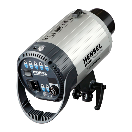
Hensel Integra Pro 500 Plus
Strobe Unit Instructions
Precautions
Read First Before Setting Up Any Lights
This compact flash unit is for indoor use only. Never use outside.
The glass dome must be installed for the safe operation of each strobe. Halogen lights and flashtubes
generate high pressure during operation and can explode, particularly if the kit is chilled in winter
during transport.
Ventilation slots of each flash unit must be kept clear of any obstruction to avoid over heating.
Do not disconnect any cords while the unit is powered up.
Never move a flash unit while it is operating. Always turn the flash off for any adjustments.
Do not run cables long distances where they could be damaged from dollies, ladders or furniture.
Do not expose any flash unit to humidity or water.
Do not connect any accessories from any other manufacturer, even if they use the same or similar
connectors.
Eye damage may occur if the flash unit is set up less than 5 meters from your subject.
Ventilate any closed rooms regularly to prevent a build-up of inadmissible ozone concentrations
which may occur during operation.
Reflectors, speedrings and other accessories heat up during long operations. To avoid injuries, handle
with gloves or wait until parts have cooled to make any adjustments.
Never over tighten any fittings. Always finger tight any knobs.
Page 1
Advertisement

Subscribe to Our Youtube Channel
Related Manuals for Hensel Integra Pro 500 Plus


Summary of Contents for Hensel Integra Pro 500 Plus
- Page 1 Hensel Integra Pro 500 Plus Strobe Unit Instructions Precautions Read First Before Setting Up Any Lights This compact flash unit is for indoor use only. Never use outside. The glass dome must be installed for the safe operation of each strobe. Halogen lights and flashtubes generate high pressure during operation and can explode, particularly if the kit is chilled in winter during transport.
- Page 2 Assembly Instructions 1. Plan out what you will need for your setup. Do not setup any unnecessary equipment. Keep It Simple! Page 2...
- Page 3 Carefully remove the light stands from the bottom side compartment of the bag and spread out the base struts horizontally for maximum footprint and stability. NOTE: Carefully lift the entire case for easy removal of the stands. **Extremely Important** 3. Place a sandbag over each leg of the stand to prevent it from falling over. NOTE: Sandbags are available for your use.
- Page 4 4. Fasten each strobe head securely to the stand. Do not over tighten. Use finger tight pressure on any knobs. Page 4...
- Page 5 5. Remove the protective plastic cap by swinging the lever at the top of each strobe. 6. Install the metal shade or softbox (additional instructions included) by swinging the lever at the top of each strobe. Page 5...
- Page 6 7. Make any adjustments to the strobe and/or setup it up in the appropriate location before turning 8. Plug in each strobe and turn it on. Wait a minute for the fan to work fully. Overview of Controls Compact Flash Unit – Compact Flash Unit –...
- Page 7 12. PROP Modeling Lamp Operation Mode & ON Indicator Flash Power Control Switch Press For Channel Selection LED Display RC = Remote Control Switch The head can become a radio control for slave purposes. Select when using the flash wizard. AUDIO Always leave this on FC = Flash Check Switch...
- Page 8 Cable Holder Pre-Fiction Tilting Head Shift to Balance Heavy Loads Clamping Screw for Umbrella Attachment Locking Screw for Head Attachment to Stand Wing Nut for Head Angle Adjustment Umbrella Installation 1. Always use a metal shade in combination with an umbrella. 2.
- Page 9 Radio Transmitter Controls Radio Transmitter Controls 21a. Flash Power Down and Modeling Light Options 21b. Flash Power Up Channel Selection for 3 Channels Test Button for Flash Socket for Included Sync Cable Hot Shoe Mounting to Camera Battery Compartment Radio Receiver Controls Radio Receiver Controls Channel Selector for 3 Channels Page 9...
- Page 10 Interface Socket Battery Compartment Slave Options There are 3 possible ways the Hensel Strobe Unit can be slaved to each other: 1. SLAVE button on the back of the head. Select the SLAVE button on each head that requires slaving.
- Page 11 Page 11...
- Page 12 Radio Transmitter Controls Radio Transmitter Controls 21a. Flash Power Down and Modeling Light Options 21b. Flash Power Up Channel Selection for 3 Channels Test Button for Flash Socket for Included Sync Cable Hot Shoe Mounting to Camera Battery Compartment 3. Sync Socket at the Top of Each Strobe cable provided in the kit for direct connection to your camera from a strobe.
- Page 13 Honeycomb Diffuser Installation 1. Insert the honeycomb ring into the large metal shade with the white tab pointing up for easy removal. Carefully secure to strobe head. Softbox Installation 1. Carefully follow the step-by-step instructions for assembly. Page 13...
- Page 14 2. The metal rods are under tension and care should be taken in their assembly and disassembly. 3. The metal shade is not required for the Softbox installation. 4. Slide the assembled Softbox carefully over the glass dome and swing the lever at the top of the head over to secure the Softbox to the head.
Need help?
Do you have a question about the Integra Pro 500 Plus and is the answer not in the manual?
Questions and answers