Table of Contents
Advertisement
Advertisement
Table of Contents

Related Manuals for Keyestudio Basic Starter Kit Series

Summary of Contents for Keyestudio Basic Starter Kit Series
-
Page 2: Table Of Contents
Catalog 1. Kit introduction .......................... 1 2. Kit contents ..........................2 3. Project list ..........................3 4. Project details ..........................4 Project 1: Hello World ......................4 Project 2: LED blinking ......................7 Project 3: PWM ........................9 Project 4: Traffic light......................14 Project 5: LED chasing effect.................... -
Page 3: Kit Introduction
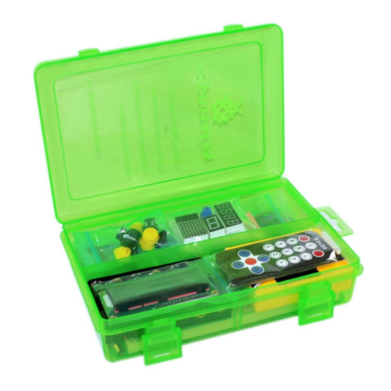
1. Kit introduction This is the basic Starter Kit, developed specially for those beginners who are interested in Arduino. You will have a set of Arduino's most common and useful electronic components. What's more. We will offer you a detailed tutorials including project introduction and their source codes.You may learn about Arduino through using these basic projects. -
Page 4: Kit Contents
2. Kit contents Kit A for unoR3 Kit B for 2560 R3 Kit C Without board UNO R3 Mega 2560 No controller board 5x LED - Blue 5x LED - Blue 5x LED - Blue 5x LED - Red 5x LED - Red 5x LED - Red 5x LED - Yellow 5x LED - Yellow... -
Page 5: Project List
3. Project list 1. Hello World 2. LED blinking 3. PWM 4. Traffic light 5. LED chase effect 6. Button-controlled LED 7. Active buzzer 8. Passive buzzer 9. RGB LED 10. Photo resistor 11. Flame sensor 12. LM35 temperature sensor 13. -
Page 6: Project Details
PC to Arduino, and assign them to Val. if(val=='R')// determine if the instruction or character received is “R”. { // if it’s “R”, digitalWrite(ledpin,HIGH);// set the LED on digital pin 13 on. delay(500); www.keyestudio.cc... - Page 7 LED on digital pin 13 off. delay(500); Serial.println("Hello World!");// display“Hello World!”string. //////////////////////////////////////////////////////////////// Result Screenshot www.keyestudio.cc...
- Page 8 Click serial port monitor Input R LED 13 will blink once; PC will receive information from Arduino: Hello World After you choose the right port,the experiment should be easy for you! www.keyestudio.cc...
-
Page 9: Project 2: Led Blinking
Project 2: LED blinking Introduction Blinking LED experiment is quite simple. In the "Hello World!" program, we have come across LED. This time, we are going to connect an LED to one of the digital pins rather than using LED13, which is soldered to the board. - Page 10 Connection for 2560 R3: www.keyestudio.cc...
-
Page 11: Project 3: Pwm
Sample program ////////////////////////////////////////////////////////// int ledPin = 10; // define digital pin 10. void setup() pinMode(ledPin, OUTPUT);// define pin with LED connected as output. void loop() digitalWrite(ledPin, HIGH); // set the LED on. delay(1000); // wait for a second. digitalWrite(ledPin, LOW); // set the LED off. - Page 12 Introduction PWM, short for Pulse Width Modulation, is a technique used to encode analog signal level into digital ones. A computer cannot output analog voltage but only digital voltage values such as 0V or 5V. So we use a high resolution counter to encode a specific analog signal level by modulating the duty cycle of PMW.
- Page 13 3. The voltage level(such as:0V-5V) There are 6 PMW interfaces on Arduino, namely digital pin 3, 5, 6, 9, 10, and 11. In previous experiments, we have done "button-controlled LED", using digital signal to control digital pin, also one about potentiometer. This time, we will use a potentiometer to control the brightness of the LED.
- Page 14 Sample program In the program compiling process, we will use the analogWrite (PWM interface, analog value) function. In this experiment, we will read the analog value of the potentiometer and assign the value to PWM port, so there will be corresponding change to the brightness of the LED. One final part will be displaying the analog value on the screen.
- Page 15 Serial.println(val);// display value of val analogWrite(ledpin,val/4);// turn on LED and set up brightness(maximum output of PWM is 255) delay(10);// wait for 0.01 second ////////////////////////////////////////////////////////// Result After downloading the program, when we rotate the potentiometer knob, we can see changes of the displaying value, also obvious change of the LED brightness on the breadboard.
-
Page 16: Project 4: Traffic Light
Project 4: Traffic light Introduction In the previous program, we have done the LED blinking experiment with one LED. Now, it’s time to up the stakes and do a bit more complicated experiment-traffic lights. Actually, these two experiments are similar. While in this traffic lights experiment, we use 3 LEDs with different color other than 1 LED. - Page 17 Connection for 2560 R3: www.keyestudio.cc...
- Page 18 Sample program Since it is a simulation of traffic lights, the blinking time of each LED should be the same with those in traffic lights system. In this program, we use Arduino delay () function to control delay time, which is much simpler than C language.
- Page 19 LOW); // turn off green LED for(int i=0;i<3;i++)// blinks for 3 times delay(500);// wait 0.5 second digitalWrite(yellowled, HIGH);// turn on yellow LED delay(500);// wait 0.5 second digitalWrite(yellowled, LOW);// turn off yellow LED delay(500);// wait 0.5 second digitalWrite(redled, HIGH);// turn on red LED delay(5000);// wait 5 second...
-
Page 20: Project 5: Led Chasing Effect
Project 5: LED chasing effect Introduction We often see billboards composed of colorful LEDs. They are constantly changing to form various effects. In this experiment, we compile a program to simulate chase effect. Hardware required 1. Led x6 2. 220Ω resistor x6 3. - Page 21 Connection for 2560 R3: www.keyestudio.cc...
- Page 22 Sample program ////////////////////////////////////////////////////////// int BASE = 2 ; // the I/O pin for the first LED int NUM = 6; // number of LEDs void setup() for (int i = BASE; i < BASE + NUM; i ++) pinMode(i, OUTPUT);...
- Page 23 (int i = BASE; i < BASE + NUM; i ++) digitalWrite(i, LOW); // set I/O pins as “low”, turn off LEDs one by one. delay(200); // delay for (int i = BASE; i < BASE + NUM; i ++) digitalWrite(i, HIGH);...
-
Page 24: Project 6: Button-Controlled Led
Project 6: Button-controlled LED Introduction I/O port means interface for INPUT and OUTPUT. Up until now, we have only used its OUTPUT function. In this experiment, we will try to use the input function, which is to read the output value of device connecting to it. - Page 25 Connection for 2560 R3: www.keyestudio.cc...
- Page 26 Sample program Now, let's begin the compiling. When the button is pressed, the LED will be on. After the previous study, the coding should be easy for you. In this program, we add a statement of judgment. Here, we use an if () statement.
- Page 27 7 and assign if to val if(val==LOW)// check if the button is pressed, if yes, turn on the LED { digitalWrite(ledpin,LOW);} else { digitalWrite(ledpin,HIGH);} ////////////////////////////////////////////////////////// Result When the button is pressed, LED is on, otherwise, LED remains off. After the above process, the button controlled LED experiment is completed.
-
Page 28: Project 7: Active Buzzer
Project 7: Active buzzer Introduction Arduino enables us to make many interesting interactive projects, many of which we have done consists of a LED. They are light-related. While this time, the circuit will produce sound. The sound experiment is usually done with a buzzer or a speaker, while buzzer is simpler and easier to use. The buzzer we introduced here is a passive buzzer. - Page 29 Connection for 2560 R3: www.keyestudio.cc...
- Page 30 When connecting the circuit, pay attention to the positive & the negative poles of the buzzer. In the photo, you can see there are red and black lines. When the circuit is finished, you can begin programming. Sample program Program is simple.
- Page 31 ////////////////////////////////////////////////////////// Result After downloading the program, the buzzer experiment is completed. You can see the buzzer is ringing. www.keyestudio.cc...
-
Page 32: Project 8: Passive Buzzer
Project 8: Passive buzzer Introduction We can use Arduino to make many interactive works of which the most commonly used is acoustic-optic display. All the previous experiment has something to do with LED. However, the circuit in this experiment can produce sound. Normally, the experiment is done with a buzzer or a speaker while buzzer is simpler and easier to use. - Page 33 Connection for 2560 R3: Sample program ////////////////////////////////////////////////////////// int buzzer=8;// select digital IO pin for the buzzer void setup() pinMode(buzzer,OUTPUT);// set digital IO pin pattern, OUTPUT to be output void loop() { unsigned char i,j;//define variable while(1) { for(i=0;i<80;i++)// output a frequency sound { digitalWrite(buzzer,HIGH);// sound...
- Page 34 ////////////////////////////////////////////////////////// After downloading the program, buzzer experiment is finished. www.keyestudio.cc...
-
Page 35: Project 9: Rgb Led
Project 9: RGB LED Introduction Tricolor principle to display various colors PWM controlling ports to display full color Can be driven directly by Arduino PWM interfaces Hardware Required Arduino controller × 1 USB cable × 1 Full-color LED module × 1 Connection for R3: www.keyestudio.cc... - Page 36 Connection for 2560 R3: Sample program ////////////////////////////////////////////////////////// int redpin = 11; //select the pin for the red LED int bluepin =10; // select the pin for the blue LED int greenpin =9;// select the pin for the green LED int val;...
- Page 37 Serial.begin(9600); void loop() for(val=255; val>0; val--) analogWrite(11, val); analogWrite(10, 255-val); analogWrite(9, 128-val); delay(1); for(val=0; val<255; val++) analogWrite(11, val); analogWrite(10, 255-val); analogWrite(9, 128-val); delay(1); Serial.println(val, DEC); ////////////////////////////////////////////////////////// Result Directly copy the above code into arduino IDE, and click upload , wait a few seconds, you can see a full-color LED www.keyestudio.cc...
-
Page 38: Project 10: Photo Resistor
Project 10: Photo resistor Introduction After completing all the previous experiments, we acquired some basic understanding and knowledge about Arduino application. We have learned digital input and output, analog input and PWM. Now, we can begin the learning of sensors applications. - Page 39 Connection for 2560 R3: www.keyestudio.cc...
- Page 40 Sample program After the connection, let's begin the program compiling. The program is similar to the one of PWM. For change detail, please refer to the sample program below. ////////////////////////////////////////////////////////// int potpin=0;// initialize analog pin 0, connected with photovaristor int ledpin=11;// initialize digital pin 11, output regulating the brightness of LED...
-
Page 41: Project 11: Flame Sensor
////////////////////////////////////////////////////////// Result After downloading the program, you can change the light strength around the photovaristor and see corresponding brightness change of the LED. Photovaristors has various applications in our everyday life. You can make other interesting interactive projects base on this one. - Page 42 As shown below: The negative of infrared receiving triode Flame sensor The positive of infrared receiving triode Connect to analog pin Hardware required 1.
- Page 43 Connect the sensor to analog pin 0. Connection for R3: Connection for 2560 R3: www.keyestudio.cc...
- Page 44 Experiment principle When it's approaching a fire, the voltage value the analog port reads differs. If you use a multimeter, you can know when there is no fire approaching, the voltage it reads is around 0.3V; when there is fire approaching, the voltage it reads is around 1.0V, tthe nearer the fire, the higher the voltage.
- Page 45 //////////////////////////////////////////////////////////////// int flame=0;// select analog pin 0 for the sensor int Beep=9;// select digital pin 9 for the buzzer int val=0;// initialize variable void setup() pinMode(Beep,OUTPUT);// set LED pin as “output” pinMode(flame,INPUT);// set buzzer pin as “input” Serial.begin(9600);// set baud rate at “9600”...
-
Page 46: Project 12: Lm35 Temperature Sensor
Project 12: LM35 temperature sensor Introduction LM35 is a common and easy-to-use temperature sensor. It does not require other hardware. You just need an analog port to make it work. The difficulty lies in compiling the code to convert the analog value it reads to celsius temperature. - Page 47 Sample program ////////////////////////////////////////////////////////// int potPin = 0; // initialize analog pin 0 for LM35 temperature sensor void setup() Serial.begin(9600);// set baud rate at”9600” void loop() int val;// define variable int dat;// define variable val=analogRead(0);// read the analog value of the sensor and assign it to val dat=(125*val)>>8;// temperature calculation formula...
- Page 48 ////////////////////////////////////////////////////////// Result After downloading the program, you can open the monitoring window to see current temperature. www.keyestudio.cc...
-
Page 49: Project 13: Tilt Switch
Project 13: Tilt switch Introduction Tilt switch controlling the ON and OFF of LED Hardware required 1. Ball switch*1 2. Led *1 3. 220Ω resistor*1 4. Breadboard jumper wires:several Connection for R3: Connection for 2560 R3: www.keyestudio.cc... - Page 50 Connect the controller board, shield, breadboard and USB cable according to Arduino tutorial. Connect the LED to digital pin 8, ball switch to analog pin 5. Experiment principle When one end of the switch is below horizontal position, the switch is on. The voltage of the analog port is about 5V (1023 in binary).
- Page 51 5 if(i>512)// if larger that 512(2.5V) digitalWrite(8,LOW);// turn on LED else// otherwise digitalWrite(8,HIGH);// turn off LED ////////////////////////////////////////////////////////// Result Hold the breadboard with your hand. Tilt it to a certain extent, the LED will be on.
-
Page 52: Project 14: Ir Remote Control
Project 14: IR remote control Introduction What is an infrared receiver? The signal from the infrared remote controller is a series of binary pulse code. To avoid interference from other infrared signals during the wireless transmission, the signal is pre-modulate at a specific carrier frequency and then send out by a infrared emission diode. - Page 53 Connection First, connect the controller board; then connect the infrared receiver as the above mentioned, connect VOUT to digital pin 11, connect the LEDs with resistors and connect the resisters to pin 2,3,4,5,6,7. Connection for R3: Connection for 2560 R3:...
- Page 54 Experimental principle If you want to decode code of a remote controller, you must first know how it's coded. The coding method we use here is NEC protocol. Below is a brief introduction. · NEC protocol: Features: (1) 8 bit address and 8 bit command length...
- Page 55 • Pulse transmitted when button is pressed and immediately released The picture above shows a typical pulse train of the NEC protocol. With this protocol the LSB is transmitted first. In this case Address $59 and Command $16 is transmitted. A message is started by a 9ms AGC burst, which was used to set the gain of the earlier IR receivers.
- Page 56 Note: when the pulse enters the integrated receiver, there will be decoding, signal amplifying and wave shaping process. So you need to make sure the level of the output is just the opposite from that of the signal sending end. That is when there is no infrared signal, the output end is in high level;...
- Page 57 (results->decode_type == NEC) Serial.print("Decoded NEC: "); else if (results->decode_type == SONY) Serial.print("Decoded SONY: "); else if (results->decode_type == RC5) Serial.print("Decoded RC5: "); else if (results->decode_type == RC6) Serial.print("Decoded RC6: "); Serial.print(results->value, HEX); Serial.print(" ("); Serial.print(results->bits, DEC); Serial.println(" bits)");...
- Page 58 INPUT); pinMode(LED1, OUTPUT); pinMode(LED2, OUTPUT); pinMode(LED3, OUTPUT); pinMode(LED4, OUTPUT); pinMode(LED5, OUTPUT); pinMode(LED6, OUTPUT); pinMode(13, OUTPUT); Serial.begin(9600); irrecv.enableIRIn(); // Start the receiver int on = 0; unsigned long last = millis(); void loop() if (irrecv.decode(&results)) // If it's been at least 1/4 second since the last // IR received, toggle the relay if (millis() - last >...
- Page 59 (results.value == on3 ) digitalWrite(LED3, HIGH); if (results.value == off3 ) digitalWrite(LED3, LOW); if (results.value == on4 ) digitalWrite(LED4, HIGH); if (results.value == off4 ) digitalWrite(LED4, LOW); if (results.value == on5 ) digitalWrite(LED5, HIGH); if (results.value == off5 ) digitalWrite(LED5, LOW);...
- Page 60 Note:add IRremote folder into installation directory \Arduino\compiler libraries, or you will not be able to compile. For example:C:\Program Files\Arduino\libraries www.keyestudio.cc...
-
Page 61: Project 15: Analog Value Reading
Project 15: Analog value reading Introduction In this experiment, we will begin the learning of analog I/O interfaces. On an Arduino, there are 6 analog interfaces numbered from 0 to 5. These 6 interfaces can also be used as digital ones numbered as 14-19. - Page 62 Connection for 2560 R3: www.keyestudio.cc...
- Page 63 We use the analog interface 0. The analog interface we use here is interface 0. Sample program The program compiling is simple. An analogRead () Statement can read the value of the interface. The A/D acquisition of Arduino 328 is in 10 bits, so the value it reads is among 0 to 1023. One difficulty in this project is to display the value on the screen, which is actually easy to learn.
- Page 64 Serial.begin(9600);// set baud rate at 9600 void loop() digitalWrite(ledpin,HIGH);// turn on the LED on pin 13 delay(50);// wait for 0.05 second digitalWrite(ledpin,LOW);// turn off the LED on pin 13 delay(50);// wait for 0.05 second val=analogRead(potpin);// read the analog value of analog pin 0, and assign it to val Serial.println(val);// display val’s value...
-
Page 65: Project 16: 74Hc595
Project 16: 74HC595 Introduction To put it simply, 74HC595 is a combination of 8-digit shifting register, memorizer and equipped with tri-state output. Here, we use it to control 8 LEDs. You may wonder why use a 74HC595 to control LED? Well, think about how many I/O it takes for an Arduino to control 8 LEDs? Yes, 8. - Page 66 Connection for 2560 R3: www.keyestudio.cc...
- Page 67 The circuit may seem completed, but once you give it a good look, you will find it easy! Sample program ////////////////////////////////////////////////////////// int data = 2;// set pin 14 of 74HC595as data input pin SI int clock = 5;// set pin 11 of 74hc595 as clock pin SCK int latch = 4;// set pin 12 of 74hc595 as output latch RCK...
- Page 68 = 0; i < 256; i++) updateLEDs(i); delay(500); void updateLEDs(int value) digitalWrite(latch, LOW);// shiftOut(data, clock, MSBFIRST, ~value);// serial data “output”, high level first digitalWrite(latch, HIGH);// latch ////////////////////////////////////////////////////////// Result After downloading the program, you can see 8 LEDs displaying 8-bit binary number.
-
Page 69: Project 17: 1-Digit Led Segment Display
Project 17: 1-digit LED segment display Introduction LED segment displays are common for displaying numerical information. It's widely applied on displays of electromagnetic oven, full automatic washing machine, water temperature display, electronic clock etc. It is necessary that we learn how it works. - Page 70 Breadboard*1 Breadboard jumper wires*several Connection Refer to below connection diagram for circuit connection Connection for R3: Connection for 2560 R3: www.keyestudio.cc...
- Page 71 Sample program There are seven segments for numerical display, one for decimal point display. Corresponding segments will be turned on when displaying certain numbers. For example, when displaying number 1, b and c segments will be turned on. We compile a subprogram for each number, and compile the main program to display one number every 2 seconds, cycling display number 0 ~ 9.
- Page 72 // display number 5 unsigned char j; digitalWrite(a,HIGH); digitalWrite(b,HIGH); digitalWrite(c,HIGH); digitalWrite(d,HIGH); digitalWrite(e,HIGH); digitalWrite(f,HIGH); digitalWrite(g,LOW); digitalWrite(dp,LOW); void digital_1(void) // display number 1 unsigned char j; digitalWrite(c,HIGH);// set level as “high” for pin 5, turn on segment c digitalWrite(b,HIGH);// turn on segment b for(j=7;j<=11;j++)// turn off other segments...
- Page 73 // display number 4 digitalWrite(c,HIGH); digitalWrite(b,HIGH); digitalWrite(f,HIGH); digitalWrite(g,HIGH); digitalWrite(dp,LOW); digitalWrite(a,LOW); digitalWrite(e,LOW); digitalWrite(d,LOW); void digital_5(void) // display number 5 unsigned char j; digitalWrite(a,HIGH); digitalWrite(b, LOW); digitalWrite(c,HIGH); digitalWrite(d,HIGH); digitalWrite(e, LOW); digitalWrite(f,HIGH); digitalWrite(g,HIGH); digitalWrite(dp,LOW); void digital_6(void) // display number 6 unsigned char j;...
- Page 74 // display number 8 unsigned char j; for(j=5;j<=11;j++) digitalWrite(j,HIGH); digitalWrite(dp,LOW); void digital_9(void) // display number 5 unsigned char j; digitalWrite(a,HIGH); digitalWrite(b,HIGH); digitalWrite(c,HIGH); digitalWrite(d,HIGH); digitalWrite(e, LOW); digitalWrite(f,HIGH); digitalWrite(g,HIGH); digitalWrite(dp,LOW); void setup() int i;// set variable for(i=4;i<=11;i++)
- Page 75 // wait for 1s digital_4();// display number 4 delay(1000); // wait for 1s digital_5();// display number 5 delay(1000); // wait for 1s digital_6();// display number 6 delay(1000); // wait for 1s digital_7();// display number 7 delay(1000); // wait for 1s digital_8();// display number 8...
-
Page 76: Project 18: 4-Digit Led Segment Display
Project 18: 4-digit LED segment display Introduction In this experiment, we use an Arduino to drive a common anode, 4-digit, 7-segment LED display. For LED display, current-limiting resistors are indispensable. There are two wiring method for Current-limiting resistor. One is to connect one resistor for each anode, 4 in totals for d1-d4 anode. - Page 77 Manual for LED segment display www.keyestudio.cc...
- Page 78 Connection for R3: Connection for 2560 R3: www.keyestudio.cc...
- Page 79 Sample Program ////////////////////////////////////////////////////////// // display 1234 // select pin for cathode int a = 1; int b = 2; int c = 3; int d = 4; int e = 5; int f = 6; int g = 7;...
- Page 80 OUTPUT); pinMode(d2, OUTPUT); pinMode(d3, OUTPUT); pinMode(d4, OUTPUT); pinMode(a, OUTPUT); pinMode(b, OUTPUT); pinMode(c, OUTPUT); pinMode(d, OUTPUT); pinMode(e, OUTPUT); pinMode(f, OUTPUT); pinMode(g, OUTPUT); pinMode(dp, OUTPUT); ///////////////////////////////////////////////////////////// void loop() Display(1, 1); Display(2, 2); Display(3, 3); Display(4, 4); /////////////////////////////////////////////////////////////// void WeiXuan(unsigned char n)//...
- Page 81 3: digitalWrite(d1,HIGH); digitalWrite(d2, HIGH); digitalWrite(d3, LOW); digitalWrite(d4, HIGH); break; case 4: digitalWrite(d1, HIGH); digitalWrite(d2, HIGH); digitalWrite(d3, HIGH); digitalWrite(d4, LOW); break; default : digitalWrite(d1, HIGH); digitalWrite(d2, HIGH); digitalWrite(d3, HIGH); digitalWrite(d4, HIGH); break; void Num_0() digitalWrite(a, HIGH); digitalWrite(b, HIGH); digitalWrite(c, HIGH);...
- Page 82 Num_2() digitalWrite(a, HIGH); digitalWrite(b, HIGH); digitalWrite(c, LOW); digitalWrite(d, HIGH); digitalWrite(e, HIGH); digitalWrite(f, LOW); digitalWrite(g, HIGH); digitalWrite(dp,LOW); void Num_3() digitalWrite(a, HIGH); digitalWrite(b, HIGH); digitalWrite(c, HIGH); digitalWrite(d, HIGH); digitalWrite(e, LOW); digitalWrite(f, LOW); digitalWrite(g, HIGH); digitalWrite(dp,LOW); void Num_4() digitalWrite(a, LOW);...
- Page 83 HIGH); digitalWrite(e, LOW); digitalWrite(f, HIGH); digitalWrite(g, HIGH); digitalWrite(dp,LOW); void Num_6() digitalWrite(a, HIGH); digitalWrite(b, LOW); digitalWrite(c, HIGH); digitalWrite(d, HIGH); digitalWrite(e, HIGH); digitalWrite(f, HIGH); digitalWrite(g, HIGH); digitalWrite(dp,LOW); void Num_7() digitalWrite(a, HIGH); digitalWrite(b, HIGH); digitalWrite(c, HIGH); digitalWrite(d, LOW); digitalWrite(e, LOW); digitalWrite(f, LOW);...
- Page 84 HIGH); digitalWrite(b, HIGH); digitalWrite(c, HIGH); digitalWrite(d, HIGH); digitalWrite(e, LOW); digitalWrite(f, HIGH); digitalWrite(g, HIGH); digitalWrite(dp,LOW); void Clear() // clear the screen digitalWrite(a, LOW); digitalWrite(b, LOW); digitalWrite(c, LOW); digitalWrite(d, LOW); digitalWrite(e, LOW); digitalWrite(f, LOW); digitalWrite(g, LOW); digitalWrite(dp,LOW); void pickNumber(unsigned char n)// select number switch(n) case 0:Num_0();...
-
Page 85: Project 19: 8*8 Led Matrix
8:Num_8(); break; case 9:Num_9(); break; default:Clear(); break; void Display(unsigned char x, unsigned char Number)// take x as coordinate and display number WeiXuan(x); pickNumber(Number); delay(1); Clear() ; // clear the screen ////////////////////////////////////////////////////////// Result Download the above code to the controller board and see the result. - Page 86 Picture of 8x8 LED matrix Pins on 8X8 LED matrix welding surface Picture of 8X8 LED matrix and pin layout In the picture, you can see an LED matrix and pin layout. You can see from the equivalent circuit that as long as the corresponding X, Y axes of an LED are in forward bias voltage, the LED will be turned on.
- Page 87 Generally, LED uses scanning for display. In practical application, it is divided into three modes (1) Dot scanning (2) Row & column scanning For mode 1, in order to meet the visual persistence requirement, the frequency should be in 16×64=1024Hz, cycle less than 1ms; for mode 2&3, the frequency should be above 16×8=128Hz, cycle less than 7.8ms.
- Page 88 ● ● ● ● ● ● ● ● ● ● ● ● ● ● ● ● As above picture shows, to display number “0”, the codes in the columns are 00H, 00H, 3EH, 41H, 41H, 3EH, 00H, 00H; send these codes to corresponding columns and you will see the display of number “0”.
- Page 89 OUTPUT); clear_(); void loop() show_num(); void clear_(void)// clear screen for(int i=2;i<10;i++) digitalWrite(i, LOW); for(int i=0;i<8;i++) digitalWrite(i+10, HIGH); ////////////////////////////////////////////////////////// Result Connection for R3: www.keyestudio.cc...
- Page 90 Connection for 2560 R3: www.keyestudio.cc...
- Page 91 Pins on 8X8 LED matrix welding surface Picture of 8X8 LED matrix and pin layout Arduino 8x8 dot matrix / / Note: look at the pin diagram backward. For example: 'H' to '0' Line correspondence: Adding 1K or 220 ohm current limiting resistor in each column...
-
Page 92: Project 20: 1602 Lcd
Project 20: 1602 LCD Introduction In this experiment, we use an Arduino to drive the 1602 LCD. 1602 LCD has wide applications. In the beginning, 1602 LCD uses a HD44780 controller. Now, almost all 1602 LCD module uses a compatible IC, so their features are basically the same. - Page 93 4. RW pin is also very common in LCD. It's a selecting pin for read/write. When the pin is in high level, it's in read operation; when it's in low level, it's in write operation. 5. E pin is also very common in LCD. Usually, when the signal in the bus is stabilized, it sends out a positive pulse requiring read operation.
- Page 94 www.keyestudio.cc...
- Page 95 Connection for R3: Connection for 2560 R3: www.keyestudio.cc...
- Page 96 Sample code A: ////////////////////////////////////////////////////////// int DI = 12; int RW = 11; int DB[] = {3, 4, 5, 6, 7, 8, 9, 10};// use array to select pin for bus int Enable = 2; void LcdCommandWrite(int value) { // define all pins int i = 0;...
- Page 97 // wait for 1ms void setup (void) { int i = 0; for (i=Enable; i <= DI; i++) { pinMode(i,OUTPUT); delay(100); // initialize LCD after a brief pause // for LCD control LcdCommandWrite(0x38); // select as 8-bit interface, 2-line display, 5x7 character size delay(64);...
- Page 98 LcdDataWrite('c'); LcdDataWrite('o'); LcdDataWrite('m'); LcdDataWrite('e'); LcdDataWrite(' '); LcdDataWrite('t'); LcdDataWrite('o'); delay(10); LcdCommandWrite(0xc0+1); // set cursor position at second line, second position delay(10); LcdDataWrite('g'); LcdDataWrite('e'); LcdDataWrite('e'); LcdDataWrite('k'); LcdDataWrite('-'); LcdDataWrite('w'); LcdDataWrite('o'); LcdDataWrite('r'); LcdDataWrite('k'); LcdDataWrite('s'); LcdDataWrite('h'); LcdDataWrite('o'); LcdDataWrite('p'); delay(5000); LcdCommandWrite(0x01); // clear the screen, cursor returns to 0 delay(10);...
- Page 99 LcdCommandWrite(0x80+5); // set cursor position at first line, sixth position delay(10); LcdDataWrite('t'); LcdDataWrite('h'); LcdDataWrite('e'); LcdDataWrite(' '); LcdDataWrite('a'); LcdDataWrite('d'); LcdDataWrite('m'); LcdDataWrite('i'); LcdDataWrite('n'); delay(5000); ////////////////////////////////////////////////////////// 4-bit connection method: When using this module, 8-bit connection uses all the digital pins of the Arduino, leaving no pin for sensors.
- Page 100 Connection for 2560 R3: After the connection, upload below code to the controller board and see how it goes. Sample code B: ////////////////////////////////////////////////////////// int LCD1602_RS=12; int LCD1602_RW=11; int LCD1602_EN=10; int DB[] = { 6, 7, 8, 9}; char str1[]="Welcome to";...
- Page 101 LCD1602_EN,HIGH); delayMicroseconds(1); digitalWrite( LCD1602_EN,LOW); temp=(command & 0x0f)<<4; for (i=DB[0]; i <= 10; i++) digitalWrite(i,temp & 0x80); temp <<= 1; digitalWrite( LCD1602_EN,HIGH); delayMicroseconds(1); digitalWrite( LCD1602_EN,LOW); void LCD_Data_Write(int dat) int i=0,temp; digitalWrite( LCD1602_RS,HIGH); digitalWrite( LCD1602_RW,LOW); digitalWrite( LCD1602_EN,LOW); temp=dat & 0xf0;...
- Page 102 <<= 1; digitalWrite( LCD1602_EN,HIGH); delayMicroseconds(1); digitalWrite( LCD1602_EN,LOW); void LCD_SET_XY( int x, int y ) int address; if (y ==0) address = 0x80 + x; else address = 0xC0 + x; LCD_Command_Write(address); void LCD_Write_Char( int x,int y,int dat) LCD_SET_XY( x, y );...
- Page 103 LCD_Command_Write(0x28);// 4 wires, 2 lines 5x7 delay(50); LCD_Command_Write(0x06); delay(50); LCD_Command_Write(0x0c); delay(50); LCD_Command_Write(0x80); delay(50); LCD_Command_Write(0x01); delay(50); void loop (void) LCD_Command_Write(0x01); delay(50); LCD_Write_String(3,0,str1);// line 1, start at the fourth address delay(50); LCD_Write_String(1,1,str2);// line 2, start at the second address delay(5000); LCD_Command_Write(0x01);...
-
Page 104: Project 21: 9G Servo Control
Project 21: 9g servo control Introduction Servomotor is a position control rotary actuator. It mainly consists of housing, circuit board, core-less motor, gear and position sensor. The receiver or MCU outputs a signal to the servomotor. The motor has a built-in reference circuit that gives out reference signal, cycle of 20ms and width of 1.5ms. The motor compares the acquired DC bias voltage to the voltage of the potentiometer and outputs a voltage difference. - Page 105 The rotate angle of the servo motor is controlled by regulating the duty cycle of the PWM(Pulse-Width Modulation) signal. The standard cycle of the PWM signal is 20ms(50Hz). Theoretically, the width is distributed between 1ms-2ms, but in fact, it's between 0.5ms-2.5ms. The width corresponds the rotate angle from 0°...
- Page 106 9 ang 10 can be used. The Arduino drive capacity is limited. So if you need to control more than one motor, you will need external power. Method 1...
- Page 107 Connect the motor to digital pin 9. Compile a program to control the motor to rotate to the commanded angle input by the user and display the angle on the screen. Sample program A ////////////////////////////////////////////////////////// int servopin=9;// select digital pin 9 for servomotor signal line int myangle;// initialize angle variable...
- Page 108 “output” Serial.begin(9600);// connect to serial port, set baud rate at “9600” Serial.println("servo=o_seral_simple ready" ) ; void loop()// convert number 0 to 9 to corresponding 0-180 degree angle, LED blinks corresponding number of time val=Serial.read();// read serial port value...
- Page 109 Sample program B: ////////////////////////////////////////////////////////// #include <Servo.h>// define a header file. Special attention here, you can call the servo function directly from Arduino's software menu bar Sketch>Importlibrary>Servo, or input #include <Servo.h>. Make sure there is a space between #include and <Servo.h>. Otherwise, it will cause compile error.
Need help?
Do you have a question about the Basic Starter Kit Series and is the answer not in the manual?
Questions and answers