Table of Contents
Advertisement
Advertisement
Table of Contents

Related Manuals for ATI Technologies 9150‑RCV‑490


Summary of Contents for ATI Technologies 9150‑RCV‑490
- Page 1 ATI Multi‑Axis, Radially‑Compliant Robotic Deburring Tool (Model 9150‑RCV‑490) Product Manual Document #: 9610‑50‑1032 Engineered Products for Robotic Productivity Pinnacle Park • 1031 Goodworth Drive • Apex, NC 27539 USA • Tel: +1.919.772.0115 • Fax: +1.919.772.8259 • www.ati‑ia.com...
- Page 2 Manual, Robotic Deburring Tool, RCV‑490 Series Document #9610‑50‑1032‑06 Foreword CAUTION: This manual describes the function, application, and safety considerations of this product. This manual must be read and understood before any attempt is made to install or operate the product, otherwise damage to the product or unsafe conditions may occur. Information contained in this document is the property of ATI Industrial Automation, Inc (ATI) and shall not be reproduced in whole or in part without prior written approval of ATI.
-
Page 3: Table Of Contents
Manual, Robotic Deburring Tool, RCV‑490 Series Document #9610‑50‑1032‑06 Table of Contents Safety ............................6 Explanation of Notifications ......................6 General Safety Guidelines ......................6 Safety Precautions ........................6 Product Overview ........................7 Tool Collet Systems ........................8 Deburring Tool Part Number Structure ..................8 Technical Description ........................ - Page 4 Manual, Robotic Deburring Tool, RCV‑490 Series Document #9610‑50‑1032‑06 Lubrication ........................... 23 Bur Inspection ..........................23 Spindle Boot Inspection ......................23 Troubleshooting and Service Procedures ................24 Troubleshooting .......................... 24 Service Procedures ........................25 6.2.1 Bur Replacement ......................25 6.2.2 Air Motor Removal and Installation .................. 27 6.2.3 Ring Cylinder Assembly Replacement ................
- Page 5 Manual, Robotic Deburring Tool, RCV‑490 Series Document #9610‑50‑1032‑06 Glossary Term Definition Device for attaching the RCV‑490 to either a robot flange or a stationary Adapter Plate mounting surface. Aerosols A suspension of fine solid or liquid particles in gas. Device for removing contamination from air supply lines. Air filters used in ATI Air Filter applications are for the removal particulates (up to 5 microns).
-
Page 6: Safety
Manual, Robotic Deburring Tool, RCV‑490 Series Document #9610‑50‑1032‑06 1. Safety The safety section describes general safety guidelines to be followed with this product, explanations of the notifications found in this manual, and safety precautions that apply to the product. Product specific notifications are imbedded within the sections of this manual (where they apply). -
Page 7: Product Overview
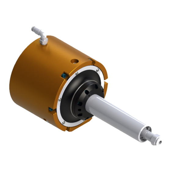
Manual, Robotic Deburring Tool, RCV‑490 Series Document #9610‑50‑1032‑06 2. Product Overview ATI Multi‑Axis, Radially‑Compliant Robotic Deburring Tool (RCV‑490) is a robust, high‑speed, and lightweight vane‑type air motor deburring unit for deburring materials, such as: aluminum, plastic, and steel with a robot. The RCV‑490 is especially suited for removal of parting lines and flash from parts. -
Page 8: Tool Collet Systems
Manual, Robotic Deburring Tool, RCV‑490 Series Document #9610‑50‑1032‑06 2.1 Tool Collet Systems The standard tool holding system for RCV‑490 series of products is an economical, industry standard ER‑11 collet design. This design is suitable for most applications where industry standard shank diameter cutting tools are used and run out tolerances of up to 0.001”... -
Page 9: Storage
Manual, Robotic Deburring Tool, RCV‑490 Series Document #9610‑50‑1032‑06 2.3.1.2 Storage Table 2.2—Storage 0 °C – 45 °C Temperature Range 32 °F – 113 °F The tool should be stored in its crate and in a dry place. When not in use, keep the unit in its crate if Conditions possible. -
Page 10: Air Motor Performance
Manual, Robotic Deburring Tool, RCV‑490 Series Document #9610‑50‑1032‑06 2.3.3 Air Motor Performance The following graphs illustrate the motor torque and power performance. The air motor operating speed changes according to the applied load, until the motor develops the power that is required to perform the specific task. -
Page 11: Installation
Manual, Robotic Deburring Tool, RCV‑490 Series Document #9610‑50‑1032‑06 3. Installation The RCV‑490 is delivered fully assembled. Optional equipment, such as: mounting adapter plates, burr tools, and additional collets will be sold separately. 3.1 Protection During Transportation The RCV‑490 is packaged in a crate that secures and protects the tool during transportation. Always use the crate when transporting the RCV‑490 in order to minimize the risk of damage. -
Page 12: Side Mounting Installation
Manual, Robotic Deburring Tool, RCV‑490 Series Document #9610‑50‑1032‑06 3.5 Side Mounting Installation CAUTION: The length of the fasteners should not interfere with the compliant motion of the air motor spindle (refer toSection 9—Drawings for the maximum fastener length) do not use fasteners that exceed the maximum length; otherwise, damage will occur. CAUTION: Lock washers are recommended on all mounting fasteners. -
Page 13: Pneumatics
Manual, Robotic Deburring Tool, RCV‑490 Series Document #9610‑50‑1032‑06 3.6 Pneumatics Connect the RCV‑490 as shown in Section 9.2—RCV Pneumatic Diagram. CAUTION: Pneumatic components used for the motor drive circuit must be capable of meeting the air consumption requirements (refer to Section 8—Specifications) Poor performance will result if the correct components are not used. - Page 14 Manual, Robotic Deburring Tool, RCV‑490 Series Document #9610‑50‑1032‑06 A second precision, self‑relieving regulator (ATI Part # 9150‑P16‑B‑G, or equivalent) and valve supply the compliance (centering) mechanism. The compliance air pressure corresponds to the side, radially applied force on the rotary bur. Adjust the compliance air pressure and robot traverse speed to achieve the desired finish.
-
Page 15: Operation
Manual, Robotic Deburring Tool, RCV‑490 Series Document #9610‑50‑1032‑06 4. Operation These operating instructions are intended to help system integrators program, start up, and set up a robotic deburring cell containing a deburring tool. The system integrator should be familiar with the task of deburring and have extensive knowledge about automation applications that incorporate robots. -
Page 16: Lubrication
Manual, Robotic Deburring Tool, RCV‑490 Series Document #9610‑50‑1032‑06 4.2.2 Lubrication Lubricate the air supply with 1‑2 drops per minute of commercial air tool oil. Vane motors for the RCV‑490 should be run with lubrication in the air supply to maximize motor life. 4.2.3 Media Selection, Design, and Maintenance Use carbide bits under 11/16"... -
Page 17: Deburring Tool Working Environment
Manual, Robotic Deburring Tool, RCV‑490 Series Document #9610‑50‑1032‑06 4.3 Deburring Tool Working Environment As described in previous sections, the RCV‑490 should only be used in conjunction with a robot in a secured work cell/chamber. The work cell must be secured by means of barriers to prohibit personnel from entering the cell. A lockable door should be included as a part of the barrier in order to facilitate access to the cell for authorized personnel only. - Page 18 Manual, Robotic Deburring Tool, RCV‑490 Series Document #9610‑50‑1032‑06 Another programming method is to teach the path using the centerline of the bur as a guide, following the edge of the part, and then manually or automatically adding offsets to the robot path points to achieve the final correct bur path (Figure 4.2).
-
Page 19: Bur Operation And Bur Selection
Manual, Robotic Deburring Tool, RCV‑490 Series Document #9610‑50‑1032‑06 4.5 Bur Operation and Bur Selection The RCV‑490 will perform best in climb milling (when the bur directions of travel and rotation are the same). In the case of the RCV‑490, the bur rotation is clockwise when viewed from above. Climb milling would therefore involve clockwise motion around the part being deburred. - Page 20 Manual, Robotic Deburring Tool, RCV‑490 Series Document #9610‑50‑1032‑06 ATI can provide guidance in bur selection; however, only experimentation will yield desired result. The following table includes many common bur types and burs recommended for particular applications. Table 4.1—Bur Selection Materials/Application Features/Benefits 9150‑RC‑B‑24033–Diamond Cut, 1/4”...
- Page 21 Manual, Robotic Deburring Tool, RCV‑490 Series Document #9610‑50‑1032‑06 Table 4.1—Bur Selection Materials/Application Features/Benefits 9150‑RC‑B‑24645–Aluminum Cut, 3/8” Bur Diameter, 5/8” Bur Length, 1/4” Shank Easy chip flow‑through positive • For greasy aluminum alloys, soft rake angle, rounded base of • non‑ferrous metals tooth, convex tooth back and thermoplastics No loading of the flutes, not...
-
Page 22: Locking And Unlocking Single Axis Compliance
Manual, Robotic Deburring Tool, RCV‑490 Series Document #9610‑50‑1032‑06 4.6 Locking and Unlocking Single Axis Compliance The RCV‑490 can be locked to be compliant in a single axis. Tools required: Flat headed screwdriver 1. Turn the single axis lockout screw as shown in Figure 4.3 for desired compliance. -
Page 23: Maintenance
Manual, Robotic Deburring Tool, RCV‑490 Series Document #9610‑50‑1032‑06 5. Maintenance The RCV‑490 is designed to provide reliable service for long periods of operation. While simple in design, there are parts in the assembly that are serviceable by the user. The user is encouraged to return the unit to ATI for service. Section 6—Troubleshooting and Service Procedures is provided to assist the user when they choose to service the unit in the field. -
Page 24: Troubleshooting And Service Procedures
Manual, Robotic Deburring Tool, RCV‑490 Series Document #9610‑50‑1032‑06 6. Troubleshooting and Service Procedures CAUTION: Thread locker applied to fasteners must not be used more than once. Fasteners might become loose and cause equipment damage. Always apply new thread locker when reusing fasteners. -
Page 25: Service Procedures
Manual, Robotic Deburring Tool, RCV‑490 Series Document #9610‑50‑1032‑06 Table 6.1—Troubleshooting Symptom Cause Resolution Not enough or Verify drive air regulator is operating at 90 psi (6.2 Bar), and no drive air check for leaks Bur is not secure Properly tighten bur in collet in collet Bur stalls Too much side load... - Page 26 Manual, Robotic Deburring Tool, RCV‑490 Series Document #9610‑50‑1032‑06 Figure 6.1—Bur Replacement 19/32” Open-end Wrench Measure and record the length of the bur extending beyond the collet nut Spindle Shaft Collet nut 11/16" Open-end Wrench Replace with new bur extend beyond collet to recorded length Pinnacle Park •...
-
Page 27: Air Motor Removal And Installation
Manual, Robotic Deburring Tool, RCV‑490 Series Document #9610‑50‑1032‑06 6.2.2 Air Motor Removal and Installation The air motor requires service after an extended operating life or following a collision. RCV‑490's with defective motors should be returned to ATI during the warranty period. Should the customer wish to replace the air motor after the warranty period, perform the following procedure: Parts required: Refer to Section 7—Serviceable... - Page 28 Manual, Robotic Deburring Tool, RCV‑490 Series Document #9610‑50‑1032‑06 13. Install the motor keeper plate, boot, and boot ring. Align dowels with corresponding dowel holes in air motor, motor keeper plate, and housing. Apply Loctite 222 to the (6) M3 socket head cap screws and the (6) M3 socket button head cap screws.
-
Page 29: Ring Cylinder Assembly Replacement
Manual, Robotic Deburring Tool, RCV‑490 Series Document #9610‑50‑1032‑06 6.2.3 Ring Cylinder Assembly Replacement The compliant motion of the air motor spindle is accomplished using an array of pistons (ring cylinder) installed inside the rear of the RCV‑490. After extended operation, this component may need to be replaced to ensure free motion of the pistons. - Page 30 Manual, Robotic Deburring Tool, RCV‑490 Series Document #9610‑50‑1032‑06 6. Install the new ring cylinder assembly. Use light grease (NLGI‑2) to lubricate the bores in the entrance to the rear housing assembly and the O‑rings in the new ring cylinder assembly. Locate the alignment mark hole on the ring cylinder and align it with the drill point on the rear housing.
-
Page 31: Muffler Replacement
Manual, Robotic Deburring Tool, RCV‑490 Series Document #9610‑50‑1032‑06 6.2.4 Muffler Replacement The compliant motion of the air motor spindle is accomplished using an array of pistons (ring cylinder) installed inside the rear of the RCV‑490. After extended operation, this component may need replacing to ensure free motion of the pistons. - Page 32 Manual, Robotic Deburring Tool, RCV‑490 Series Document #9610‑50‑1032‑06 6. Install the muffler. Install the (2) O‑rings to secure the muffler in place. Figure 6.5—Muffler Installation (6) M4 Socket Head Cap Screw Main Housing Assembly Muffler (2) O-ring Rear Housing Assembly 7.
-
Page 33: Boot Replacement
Manual, Robotic Deburring Tool, RCV‑490 Series Document #9610‑50‑1032‑06 6.2.5 Boot Replacement The boot prevents debris from entering the housing and protects internal components. Replace the boot if it shows signs of damage (refer toFigure 6.3e 6.3) Parts required: Refer to Section 7—Serviceable Parts. -
Page 34: Serviceable Parts
Manual, Robotic Deburring Tool, RCV‑490 Series Document #9610‑50‑1032‑06 7. Serviceable Parts The serviceable parts for the 9150‑RCV‑490 are in the following table: Part Number Description 3490‑0001063‑01 Vane Motor, EG20, 496 Watts, 30,000 rpm 9005‑50‑6061 Ring Cylinder Assembly, RCV‑490 3700‑50‑9042 Muffler Strip, Scotchbrite, RCV‑490 3410‑0001025‑01 O‑Ring AS568‑034 Buna‑N D70 (for muffler) 3700‑50‑9039... -
Page 35: Specifications
Manual, Robotic Deburring Tool, RCV‑490 Series Document #9610‑50‑1032‑06 8. Specifications Parameter Rating Motor Pneumatic Vane‑Type Idle Speed (RPM) 30,000 Working Speed (RPM) 15,000 (Approximate) Torque (Max. Power) 1.4 in‑lbs (0.16 Nm) Power 0.66 hp (490 Watts) Weight (without Adapters 7.4 lb (3.36 kg) Compensation (Radial) +/‑... -
Page 36: Drawings
Manual, Robotic Deburring Tool, RCV‑490 Series Document #9610‑50‑1032‑06 9. Drawings 9.1 RCV‑490 Drawing Pinnacle Park • 1031 Goodworth Drive • Apex, NC 27539 USA • Tel: +1.919.772.0115 • Fax: +1.919.772.8259 • www.ati‑ia.com... - Page 37 Manual, Robotic Deburring Tool, RCV‑490 Series Document #9610‑50‑1032‑06 Pinnacle Park • 1031 Goodworth Drive • Apex, NC 27539 USA • Tel: +1.919.772.0115 • Fax: +1.919.772.8259 • www.ati‑ia.com...
-
Page 38: Rcv Pneumatic Diagram
Manual, Robotic Deburring Tool, RCV‑490 Series Document #9610‑50‑1032‑06 9.2 RCV Pneumatic Diagram Pinnacle Park • 1031 Goodworth Drive • Apex, NC 27539 USA • Tel: +1.919.772.0115 • Fax: +1.919.772.8259 • www.ati‑ia.com... -
Page 39: Axial Air Supply Interface Plate
Manual, Robotic Deburring Tool, RCV‑490 Series Document #9610‑50‑1032‑06 10.2 Axial Air Supply Interface Plate Pinnacle Park • 1031 Goodworth Drive • Apex, NC 27539 USA • Tel: +1.919.772.0115 • Fax: +1.919.772.8259 • www.ati‑ia.com... -
Page 40: Terms And Conditions Of Sale
Manual, Robotic Deburring Tool, RCV‑490 Series Document #9610‑50‑1032‑06 10. Terms and Conditions of Sale The following Terms and Conditions are a supplement to and include a portion of ATI’s Standard Terms and Conditions, which are on file at ATI and available upon request. ATI warrants the compliant tool product will be free from defects in design, materials, and workmanship for a period of one (1) year from the date of shipment and only when used in compliance with the manufacturer's specified normal operating conditions. -
Page 41: Motor Life And Service Interval Statement
Manual, Robotic Deburring Tool, RCV‑490 Series Document #9610‑50‑1032‑06 10.1 Motor Life and Service Interval Statement The air motors that are used in ATI deburring/finishing tools are subject to wear and have a finite life. Motors that fail, during the warranty period, will be repaired or replaced by ATI as long as there is no evidence of abuse or neglect and that the normal operating practices outlined in this manual have been observed.
Need help?
Do you have a question about the 9150‑RCV‑490 and is the answer not in the manual?
Questions and answers