Table of Contents
Advertisement
Quick Links
Advertisement
Table of Contents

Related Manuals for Flexit CS2000 V2


Summary of Contents for Flexit CS2000 V2
- Page 1 112140E-03 2016-01 CS2000 Automatic control V2 User Guide...
-
Page 2: Table Of Contents
Contents This user guide only applies to software version V2.x To view current software version: Start page > Main menu > System Overview > Versions > Flexit.ahu = V2.x 1. Introduction 1.1. Document description ....................................................1.2. Highlighted boxes ......................................................... - Page 3 7. General functions 7.1. Operating modes ......................................................... 7.1.1. Operating modes - Change ..........................................7.1.2. Operating modes - Monitor ..........................................7.2. Timing program ........................................................7.2.1. General ........................................................7.2.2. Settings ....................................................... 8. Configuration 8.1. Configuration menu ......
-
Page 4: Introduction
1. Introduction 1.1. Document description This document describes the main functions of the CS2000 automatic control and is divided into different sections for different parts of the system. If you only want to make basic settings to start the ventilation unit, there is a special section describing the startup procedure. -
Page 5: System Overview
1.3. System overview 1.3.1. System structure The control system is divided into two subgroups: 1. One part that is located in the ventilation unit's switching space 2. One part that is located in a separate control cabinet on the outside of the ventilation unit. Terminal blocks for incoming feed Fuse for Control unit - the overall control system of the automatic control and fans (not electric... -
Page 6: Ventilation Unit's Switching Space
1.3.2. Ventilation unit's switching space Modbus extender Power supply board USER FACTORY PE PE PE L1 L2 L3 N 1 2 3 4 5 6 7 8 9 10 11 12 13 14 It is a circuit board that distributes the power supply to the components of the ventilation unit (not the electric heating coil) and control cabinet. -
Page 7: Ventilation Unit's Control Cabinet
1.3.3. Ventilation unit's control cabinet Control unit Terminal board 1 2 3 4 5 6 7 8 9 10 11 12 13 14 15 16 17 18 19 20 21 22 23 24 25 26 27 28 29 30 31 32 33 34 35 36 37 38 39 40 41 42 43 44 The ventilation unit's control unit This is where the control It is a circuit board that connects the components to the panel (HMI) and sensors and other components of the... - Page 8 Terminal board Terminal block P10 has the following signals: Terminal block P12 has the following signals: Block no. Function Block no. Function Cooling - 0-10V [AO] Cooling - G0 L (Outdoor air damper) External control 1 [DI] L1 (Outdoor air damper ON/OFF) External control 1 - G0 N (Outdoor air damper) External control 2 [DI]...
-
Page 9: Getting Started
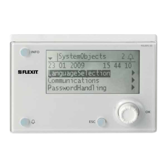
2. Getting started 2.1. HMI A central element in the system is the HMI (control panel), where you can adjust settings and take readings. The control panel consists of an 8-line graphic display, indicator lamps and controls for the settings. Here is a short introduction to the control panel showing how to enter the initial settings in the system. -
Page 10: Adjust Setpoints
Rights to all menus except I/O configuration and system settings. Level 4: OEM, password given only in consultation with the Activate the function on the menu selection: Flexit service organisation. Main index > Configuration > Configuration 1 > Tmp. • All rights as for level 3, plus: control mode = Room or Exhaust •... -
Page 11: Set The Calendar And Timing Program
2.6. Set the calendar and timing program 2.6.1. General This section describes functions and settings for the timing program and calendars. When no object with higher priority (for example Manual operation <> Auto) is activated, the system can be disconnected or the stages altered from the timing program. A maximum of six switch-over times can be specified per week. -
Page 12: Calendar (Exceptions And Stop)
2.6.4. Calendar (exceptions and stop) EXAMPLE: Val-x = Date Exception days can be defined in the calendar. These can Only the time for (start) is relevant. include specific days, periods or weekdays. Exception days override the weekly schedule. • -(Start)Date = *,01.01.09 Calendar exceptions Result: 1 January 2009 is an exception date. -
Page 13: Menu Tree
3. Menu tree When you log in, more options are visible in the menu tree. Be aware that this menu tree only shows the standard application and it might change when you reconfigure the controlling unit. Nivå 3 Nivå 1 Nivå... - Page 14 • Outputs alarm • Energy meter EM24 Settings Inputs • Room units Configuration Settings Inputs Configuration by • Flexit MB-Extender • Configuration 1 Settings • Configuration 2 • Config. IO’s • Reset required • Check config lO’s Doubled Not configured...
- Page 15 Start page Main index Unit • Main overview • Inputs • Outputs • Operating mode • Setpoints/settings • Damper control • Fan control • Temp control • Loop controllers • Operating hours Main overview Operating mode Temp control Actual • Act controlled tmp Operating State •...
- Page 16 Start page Main index Integrations • Energy meter EM24 Settings Inputs • Room units Settings Inputs • Flexit MB-Extender Settings • Reset required Flexit MB-Extender • Modbus Address • Baudrate • Stopbit • ModbusParity • Warn • Device Mode •...
- Page 17 Versions MSR failure type Conf load SD done Act. object memory Application info MSR started up Restart required Act. int. memory Flexit Advanced Sett. service load COV act. clients STD_AHU_v207 Sett. factory load ALH act clients dato Sett. service save...
- Page 18 Start page Configuration Main index Configuration by • Configuration 1 • Configuration 2 • Config. IO’s • Check config lO’s Doubled Not configured Configuration IO's Configuration 1 Configuration 2 • Temperatures General: Night cooling Extension modules Tmp start • Pressures / flows Fire alarm Boost •...
-
Page 19: System Settings
Level 4: OEM, password given only in consultation with the Flexit service organisation. Change Go to the Process unit settings page • All rights as for level 4, plus: settings •... -
Page 20: Hmi
5.2. HMI Main index > System overview > HMI Parameter Value Function • Current English Shows current language and • language Norwegian language options. • Swedish • Danish • Finnish Logout time 3...30 [min] The user is automatically logged out after a certain Location of SD period of inactivity, and has memory card... -
Page 21: Loan An Application Or Software
6.3. Loan an application or software 7. General functions Preconditions: 7.1. Operating modes • The (uncompressed) files must be in the root folder of There are a number of different operating modes, depending the SD memory card. on the functions activated in the system. To see the current •... - Page 22 Parameter Value Function Parameter Value Function Current Operating mode: • • Manual Comf.St2 System in economy operation • • Switched off. operation in step 2 (uses setpoint step 2 • • On/Comf. Comfort operation (comfort for analogue outputs). temperature setpoint) •...
-
Page 23: Timing Program
7.2. Timing program Parameter Value Function 7.2.1. General • From BMS System in comfort operation To use the timing program, the function must be activated. in step 1 (uses setpoint step 1 This is done via the menu option: • for analogue outputs). - Page 24 Calendar (exceptions and stop) Week schedule Exception days can be defined in the calendar. These can Parameter Value Function include specific days, periods or weekdays. Exception days Current value Switching according to schedule. override the weekly schedule. Monday Shows current command when the Calendar exceptions current day is Monday.
- Page 25 EXAMPLE: Val-x = Date Only the time for (start) is relevant. • -(Start)Date = *,01.01.09 Result: 1 January 2009 is an exception date. • -(Start)Date = Mo,*.*.00 Every Monday is an exception day • -(Start)Date = *,*.Even.00 All days in even months (February, April, June, August, etc.) are exception days.
-
Page 26: Configuration
8. Configuration 8.1.1. Configuration via On delivery, the ventilation unit is configured and ready. There are two options under this item: Normally, therefore, no adjustments need to be made to the configuration. HMI: The system is configured step by step via the control panel. However, the addition of accessories and other equipment may require a change to the configuration. -
Page 27: Configuration 1
Configuration 1 8.1.2. If adjustments are needed, 'Configuration 1' is the first step in the configuration. Configuration is done sequentially, which means that it • is not possible to skip any options. Configuration 1 must have been completed and the •... - Page 28 Parameter Value Function Timing program Activation of possible fan steps. This setting controls the number of setpoints for regulated fans. step Step 1 Timing program function = Step ---> Possible settings for timing program: Off, St1. Timing program function = Step+Temp ---> Possible settings for timing program: Off, Econ1, Comf1. Step 2 Timing program function = Step --->...
- Page 29 Parameter Value Function Functions: Damper No air damper. Comb. Two air dampers with a common output. Supply air Supply air damper with output. Outdoor+ Two dampers with separate outputs. Extract air Extract air fan Extract air fan (supply air fan is always available and cannot be deactivated). None No extract air fan.
- Page 30 Parameter Value Function Heating No heating circuit. Heating register without preheating. Analogue heating valve output. Yes+Preh. Heating register with preheating. Analogue heating valve output. Electric heating Electric heating register and type of regulation. No electric heating register available. Analogue Electric heating register with regulation via one analogue output. 1Step 1-step electric heating register with regulation via one analogue and one digital output.
-
Page 31: Configuration
8.1.3. Configuration 2 If there is a need for adjustments, subfunctions for some parts of the system can be set in Configuration 2. Preconditions Configuration 1 must have been completed, including restart of the regulator. Configuration is done sequentially, which means that it is •... - Page 32 Parameter Value Function Flow display Display of flow and possible output. The function is not available. Flowing Shows supply air and extract air flow (depending on what is activated). Analogue inputs are activated unless they have been activated via the fan regulation setting. Fan step type Necessary fan regulation output that concerns settings for Fan regulation type, Timing program step and Dig.step freq.conv.
- Page 33 Parameter Value Function Fan heating/cooling The fan is used as heating or cooling sequence. No sequential fan activation. Heating Fan activation only in connection with heating sequence. Cooling Fan activation only in connection with cooling sequence. HeatingCooling Fan activation in connection with both sequences Temp.
- Page 34 Parameter Value Function Recovery frost No frost protection for heat recovery. protection Guard Frost protection via guard. Digital input for frost guard. Temp. Frost protection via sensor. One analogue input for regulated frost protection via setpoint. Rotating heat exchanger and plate heat exchanger: extract air sensor, water heat exchanger: water sensor Temp+Guard Frost protection via sensor and guard.
- Page 35 Parameter Value Function Electric heating No alarm. alarm One digital alarm input is activated (logical 1 = alarm). Cooling pump No water cooling pump. Water cooling pump without pump motion. Digital pump output. Yes+Motion Water cooling pump with pump motion. One digital pump output and activation of pump motion. Pump motion: The pump is started for a short time after having been idle for a long time.
- Page 36 Parameter Value Function Pump alarm, Pump without alarm or return. Ex. cooling Alarm Pump with alarm. Digital input for pump alarm. Logical 1 = alarm; pump immediately switched off. Return. Pump with return. Digital input for return (logical 1 = activated pump). Alarm+Return Pump with alarm and return.
-
Page 37: Configuration Of Inputs And Outputs
8.1.4. Configuration of inputs and outputs NB! The ventilation unit is supplied fully configured and does not normally need to be changed. If there is a need for adjustments, subfunctions for some parts of the system can be set in Configuration 1, Configuration 2 and Configuration of inputs and outputs. -
Page 38: Cooling
9. Cooling 9.1. Cooling It is possible to choose between cold water register and DX cooling. The cold water register can be used with or without a pump (pump motion). The register for DX cooling has one step. The cooling registers are deactivated if the outdoor air temperature is too low and are forced off in connection with: •... -
Page 39: Configuration - Dx Cooling
Cold water register Main index > Configuration > Configuration 2 > Cooling pump Area Function No cooling register pump Cooling register pump without pump motion Yes+Motion Cooling register pump with pump motion RESTART 9.1.3. Configuration - DX cooling DX cooling Main index >... - Page 40 Cooling - parameters Main index > Unit > Temp control > Cooling > Regulator Cooling Area Function Shows the current cooling Regulator output signal 0.0% regulator value Current value 52.5 Shows the current value for Setpoint 22.0°C the cooling valve's output -64..+64°C Block.
-
Page 41: Temperature Regulation
10. Temperature regulation 10.1. Select method of regulation 10.1.1. Select temperature regulation method All temperature regulation functions are selected under the Set parameters in the menu options: menu option: Main index > Unit > Temp control > Setpoints > Summer comp. - Page 42 10.1.2.1. Nighttime cooling 10.1.2.2. Support operation Activate the function in the menu option: Activate the function in the menu option: Main index > Configuration > Configuration 2 > Night Main index > Configuration > Configuration 2 > cooling Support operation RESTART RESTART With nighttime cooling, the building is cooled at night using...
-
Page 43: Fan Regulation
Heating and cooling can be activated separately. 11. Fan regulation The function can be implemented using an extract air sensor if there is no room sensor. 11.1. Select method of regulation 11.1.1. Selection fan regulation method Cooling requirements All fan regulation functions are selected under the menu option: Optimised start for cooling requirements is activated when the following preconditions are met: Main index >... - Page 44 11.1.1.4. Supply air fan slave The supply air fan is driven dependent on the extract air fan [Pa]/[l/s]. The extract air fan is pressure-regulated and the extract air flow is calculated so that the supply air fan is flow-regulated accordingly. Set parameters in the menu option: Main index >...
-
Page 45: Connection Of External Equipment
12. Connection of external equipment 12.1. General External equipment is connected to the blocks in the control cabinet. The P10 contact has connections for power current (230V) The P12 contact has connections for low current (< 24V) 1 2 3 4 5 6 7 8 9 10 11 12 13 14 15 16 17 18 19 20 21 22 23 24 25 26 27 28 29 30 31 32 33 34 35 36 37 38 39 40 41 42 43 44 Contact P12... -
Page 46: Outdoor Air Damper
12.2. Outdoor air damper 12.5. Buzzer alarm Connection of outdoor air damper. Connection of signal for detecting a buzzer alarm. Block Function Block Function Relay contact NO (closes on alarm) L - Constant 230V Relay contact NO (closes on alarm) L1 - 230V ON/OFF control N - Constant N The buzzer alarm is common to both A alarm and B alarm. -
Page 47: External Speed Control
12.8. External speed control 12.10. Air quality Connection of signal(s) for controlling fan speed from Connection of a sensor for air quality measurement. external components. Block Function Block Function Air quality - 0-10 [AI] External control 1 [DI] Air quality - G0 External control 1 - G0 The function must be activated in the control unit. - Page 48 Flexit AS, Televeien 15, N-1870 Ørje www.flexit.no...
Need help?
Do you have a question about the CS2000 V2 and is the answer not in the manual?
Questions and answers