
Related Manuals for RGBlink RHOX RMS 5533


Summary of Contents for RGBlink RHOX RMS 5533
- Page 1 RMS 5533 User Manual Manual #: RGB-RD-UM-R5533 E001 Revision: V1.4 RMS 5533 User Manual...
- Page 2 Technology Co.,LTD. No part can be copied, reproduced or translated without permission. Notice RGBlink provides this manual ―as is‖ without warranty of any kind, no matter expressed or implied, including but not limited to the implied warranties or merchantability and fitness for a particular purpose. RGBlink may make improvements or changes to the products and the programs described in this publication at any time without notice.
- Page 3 30 days after the transfer of risks. In the event of justified notice of compliant, RGBlink can repair the fault or provide a replacement at its own discretion within an appropriate period. If this measure proves to be impossible or unsuccessful, the purchaser can demand a reduction in the purchase price or cancellation of the contract.
- Page 4 Company Address Xiamen RGBlink Science & Technology Co., Ltd. Headquarter: S603~604 Wei ye Building Torch Hi-Tech Industrial Development Zone Xiamen, Fujian Province, P.R.C Shenzhen office: Floor 11, A1 Building, Baiwang R&D Building, Shahe West Road, Xili Town, Nanshan District, Shenzhen, Guangdong Province, P.R.C...
- Page 5 Safe Operation Summary The general safety information in this summary is for operating personnel. Do Not Remove Covers or Panels There are no user-serviceable parts within the unit. Removal of the rear panel will expose dangerous voltages. To avoid personal injury, do not remove the rear panel.
- Page 6 Terms and Equipment Mark in This Manual WARNING Highlight an operating procedure, practice, condition, statement, etc, which, if not strictly observed, could result in injury or death of personnel. Note Highlights an essential operating procedure, condition or statement. CAUTION The exclamation point within an equilateral triangle is intended to alert the user to the presence of important operating and maintenance (servicing) instructions in the literature accompanying the appliance.
- Page 7 Amendment Record The table below lists the changes to the Rack Mount Monitor User Manual. Format Time ECO# Description Principal 2012-11-02 0000 Release 2013-01-31 0001 Interface Upgrade Vira Update the menu and SDI module 2015-01-15 0002 Vira 1. Add the ―Hardware Installation‖. 2.
-
Page 8: Table Of Contents
CONTENT CONTENT ..................... 8 1. Brief Introduction ............... 11 Chapter Structure ................12 Manual Usage ................... 13 Terms and Definitions ..............14 Product Feature ................20 2. Panel Instruction ................ 21 In This Chapter ................. 21 RMS 5533 Front Panel ..............22 1.Phone .................... - Page 9 1: Power ....................24 2: TALLY Control Port ................24 3: SDI Loop Out..................24 4: SDI Input ....................25 5: CVBS Input ................... 25 6:CVBS Loop Out.................. 25 7: DVI/VGA Loop Out ................25 8: DVI/VGA Input ..................25 9: USB Port ....................
- Page 10 F Key Submenu ................35 VGA Setup Submenu ............... 36 5. System Setup and Operation ........... 37 In This Chapter ................. 37 How to Turn on/off the Monitor ............38 How to Monitor the Audio ..............39 How to Choose the Signal ............... 40 How to Use User Defined Function Key ........
-
Page 11: Brief Introduction
Brief Introduction This chapter is designed to introduce you to the RMS 5533 User Manual. It covers: Chapter Structure Manual Usage Terms and Definitions Product Feature RMS 5533 User Manual... -
Page 12: Chapter Structure
1. Brief Introduction Chapter Structure Chapter Structure The following chapters provide instructions for all aspects of RMS 5533 operations: Chapter 1 Brief Introduction Chapter 2 Panel Instruction Chapter 3 Hardware Installation Chapter 4 Menu Operation Chapter 5 System Setup and Operation Chapter 6 TALLY Light Operation Appendix A... -
Page 13: Manual Usage
1. Brief Introduction Manual Usage Manual Usage Following are important tips for streamlining your use of this User’s Guide in its electronic ―PDF‖ form. Navigation Use Acrobat Reader’s ―bookmarks‖ to navigate to the desired location. All chapter files have the same bookmark structure for instant navigation to any section. -
Page 14: Terms And Definitions
1. Brief Introduction Terms and Definitions Terms and Definitions The following terms and definitions are used throughout this guide; “ASCII”: American Standard for Information Interchange. The standard code consisting of 7-bit coded characters (8 bits including parity check) used to exchange information between data processing systems, data communication systems, and associated equipment. - Page 15 1. Brief Introduction Terms and Definitions computer, the most commonly used color bars are two rows of reversed color bars. “Color burst”: In color TV systems, a burst of sub-carrier frequency located on the back porch of the composite video signal. This serves as a color synchronizing signal to establish a frequency and phase reference for the chrome signal.
- Page 16 1. Brief Introduction Terms and Definitions uncompressed high definition video, up to 8 channels of audio, and control signals, over a single cable. HDMI is the de facto standard for HDTV displays, Blu-ray Disc players, and other HDTV electronics. Introduced in 2003, the HDMI specification has gone through several revisions.
- Page 17 1. Brief Introduction Terms and Definitions separate scaler for each video window. “Polarity”: The positive and negative orientation of a signal. Polarity usually refers to the direction or a level with respect to a reference (e.g. positive sync polarity means that sync occurs when the signal is going in the positive direction).
- Page 18 1. Brief Introduction Terms and Definitions when switching between sources. “SMPTE”: Society of Motion Picture and Television Engineers. A global organization, based in the United States that sets standards for base band visual communications. This includes film as well as video and television standards.
- Page 19 1. Brief Introduction Terms and Definitions analog signal with TTL level separate horizontal and vertical sync. The video outputs to a 15-pin HD connector and has a horizontal scan frequency of 31.5 kHz and vertical frequency of 70 Hz (Mode 1, 2) and 60 Hz (Mode 3).
-
Page 20: Product Feature
1. Brief Introduction Product Feature Product Feature High Resolution LCD Panel Consists of three 5-inch, 16:9, 800X480 LCD panel, with wide viewing angle and 19-inch 3U rack mount. Underscan and Overscan Switch between underscan and overscan mode. Pixel to pixel zoom-in The real time zoom-in function is to enlarge to the input video as pixel to pixel from the center. -
Page 21: Panel Instruction
Panel Instruction In This Chapter This chapter provides detailed information about the RMS 5533 panel. The following topics are discussed: RMS 5533 Front Panel RMS 5533 Back Panel RMS 5533 User Manual... -
Page 22: Rms 5533 Front Panel
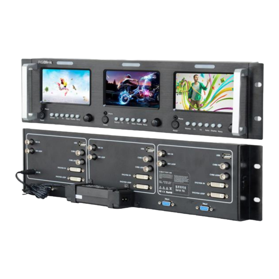
2. Panel Instruction RMS 5533 Front Panel RMS 5533 Front Panel Front view: 1.Phone 3.5mm earphone jack, for HDMI (supported by DVI input) and SDI embedded audio monitoring. 2.Power Power on/off indicator. Plug in the power cord, push the ―Power‖ button and the power indicator is turned on and after 10 seconds, the monitor will be switched on and get into working status. -
Page 23: 5.F2
2. Panel Instruction RMS 5533 Front Panel User defined function key 1. 5.F2 User defined function key 2. 6.Ratio Aspect ratio. Push the ―Ratio‖ button, user can choose the ration between 16:9 and 4:3. 7.Display Display current settings. Push the ―Display‖ button to display marker, title and the current input signal information. -
Page 24: Rms 5533 Back Panel
2. Panel Instruction RMS 5533 Back Panel RMS 5533 Back Panel Back view: INTERFACE INTERFACE Power CVBS Loop Out TALLY Control Port DVI/VGA Loop Out SDI Loop Out DVI/VGA Input SDI Input USB Port CVBS Input 1: Power DC 12V IN: Connect with DC12V power adapter. Power polarity is: negative inside and cathode outside. -
Page 25: 4: Sdi Input
2. Panel Instruction RMS 5533 Back Panel 4: SDI Input SDI IN: Standard BNC Connector. 5: CVBS Input CVBS IN: Composite video input (BNC connector). 6:CVBS Loop Out CVBS LOOP: Composite video loop out (BNC connector, it is valid only when switch the signal to AV channel). - Page 26 2. Panel Instruction RMS 5533 Back Panel Input formats Input Supported formats CVBS PAL/NTSC 480i / 576i / 480p / 576p 1080i ( 60 / 59.94 / 50) 720p ( 60 / 59.94 / 50) 1080p ( 60 / 59.94 / 50 / 30 / 29.97 / 25 / 24 / 23.98) 800x600@60Hz 1024x768@60Hz 1024x768@75Hz...
-
Page 27: Hardware Installation
Hardware Installation In This Chapter This chapter provides comprehensive installation instruction for RMS 5533 hardware: Following is the size of RMS 5533 for your reference: RMS 5533 User Manual... -
Page 28: Safety Precautions
Safety Precautions For all RMS 5533 processor installation procedures, please observe the following important safety and handling rules to avoid damage to yourself and the equipment. To protect users from electric shock, ensure that the chassis connects to earth via the ground wire provided in the AC power Cord. ... -
Page 29: Menu Operation
Menu Operation In This Chapter This chapter provides menu operation about the RMS 5533. Including: how to be visited, the available functions, and the description of menu item. The following topics are discussed: MENU System Submenu Picture Submenu ... -
Page 30: Menu
4. Menu Operation MENU MENU Language setting The language in menu is optional, it includes Chinese, English, etc. English is the default language. Following is the operation for how to change English to Chinese, and the opposite applies as well. 1. -
Page 31: System Submenu
4. Menu Operation System Submenu System Submenu The System Submenu includes: 1. RATIO: Aspect ratio has two options, 16:9 and 4:3. 2. SCAN: ―Underscan‖ / ―Overscan‖ selection. 3. ZOOM: ―OFF‖, ―Zoom1‖ and ―Zoom2‖ selection. Zoom1: Canon DSLR scale zoom-in. Zoom2: Pixel to Pixel zoom-in. 4. -
Page 32: Picture Submenu
4. Menu Operation Picture Submenu Picture Submenu The Picture Submenu includes: 1. CONTRAST: The adjustment range is 0~100. 2. BRIGHTNESS: The adjustment range is 0~100. 3. SATURATION: The adjustment range is 0~100. 4. SHARPNESS: The adjustment range is 0~100. 5. COLOR TEMP: Color temperature, cool selection, normal, warm, user defined. -
Page 33: Osd Submenu
4. Menu Operation OSD Submenu OSD Submenu The OSD Submenu includes: 1. LANGUAGE: Can choose Chinese or English. 2. H-POSITION: Adjust the horizontal position of the menu window, the adjustment range is 0~100. 3. V-POSITION: Adjust the vertical position of the menu window, the adjustment range is 0~100. -
Page 34: Display Submenu
4. Menu Operation Display Submenu Display Submenu Enter to ―Display‖ submenu, to set the following items: 1. INFO: Select ―ON‖, screen will display ―Input Format‖, ―RATIO‖, ‖SCAN‖, ―MARKER‖, ―FLIP‖, ‖ZOOM‖ at the up-left. 2. MARKER: Safe area. Select ―ON‖, screen will display the safe area, and select ―OFF‖... -
Page 35: F Key Submenu
4. Menu Operation F Key Submenu F Key Submenu Enter to ―FKEY― submenu, user defined F1/F2 functions. The available function items are: RATIO: Aspect ratio switch. SCAN: Underscan / Overscan switch. ZOOM: Picture Zoom-in. FLIP: Image flip. PIC MODE: Preset picture mode switch. CLR TEMP: Color-temperature switch. -
Page 36: Vga Setup Submenu
4. Menu Operation VGA Setup Submenu VGA Setup Submenu Enter to ―VGA Setup‖ submenu to adjust VGA-HPOS (0~100), VGA-VPOS (0~100), CLOCK (0~100), PHASE (0~100). Also can select ―ON‖ at ―AUTO ADJUST‖ to adjust when input VGA signal. RMS 5533 User Manual... -
Page 37: System Setup And Operation
System Setup and Operation In This Chapter This chapter focuses on system setup and operation, mainly including the following contents: How to Turn on/off the Monitor How to Monitor the Audio How to Choose the Signal How to Use User Defined Function Key ... -
Page 38: How To Turn On/Off The Monitor
5. System Setup and Operation How to Turn on/off the Monitor How to Turn on/off the Monitor 1. Plug in the power cord. 2. Push the ―Power‖ button, the button light is on, about 10 seconds later, the monitor begins to work. 3. -
Page 39: How To Monitor The Audio
5. System Setup and Operation How to Monitor the Audio How to Monitor the Audio First, ensure the monitor power on and in normal operation. Specific operations as follows: 1. Push the ―Source‖ button, and push ―OK‖ knob to choose signal. 2. -
Page 40: How To Choose The Signal
5. System Setup and Operation How to Choose the Signal How to Choose the Signal First, ensure the monitor power on and in normal operation. Specific operations as follows: 1. Push the ―Source‖ button, and LCD screen displays as follows: 2. -
Page 41: How To Use User Defined Function Key
5. System Setup and Operation How to Use User Defined Function Key How to Use User Defined Function Key First, ensure the monitor power on and in normal operation. Specific operations as follows: 1. Push the ―Menu‖ button, and enter to ―Menu‖ system. Rotate the knob, and choose ―FKEY‖... -
Page 42: How To Display Aspect Ratio
5. System Setup and Operation How to Display Aspect Ratio How to Display Aspect Ratio First, ensure the monitor power on and in normal operation. Specific operations as follows: 1. Push the ―Ratio‖ button. 2. Push the ―OK‖ button to choose the aspect ratio, aspect ratio has two options, 16:9 and 4:3. -
Page 43: How To Display Current Settings
5. System Setup and Operation How to Display Current Settings How to Display Current Settings 1. First, ensure the monitor power on and in normal operation. 2. Push the ―DISPLAY‖ button, the LCD screen displays the current input signal information, including: RATIO SCAN MARKER... -
Page 44: Tally Light Operation
TALLY Light Operation Terminal Description 1. There are front TALLY lights on each of the display units, which can display RED, GREEN and YELLOW signals. 2. The TALLY light controlling port is the RS232 socket at the rear panel, and terminal description as above. 3. -
Page 45: Specification
Specification LCD Performance Size 5.0 inches x3 Resolution 800xRGBx480 Color 4677 million colors Aspect ratio 16:9 / 4:3 Brightness 350cd/m² Contrast 500:1 Viewing angle Horizontal /Vertical:140° /120° Video Format CVBS NTSC / PAL SMPTE-425M 1080p ( 60 / 59.94 / 50) 1080i ( 60 / 59.94 / 50) SMPTE-274M 1080p ( 30 / 29.97 / 25 / 24 / 23.98) - Page 46 General Working voltage DC 12V Power consumption ≤24W Working temperature 0℃~+40℃ Working humidity 10%~90% Storage temperature -15℃~+60℃ Storage humidity 10%~90% Dimensions 480mmX129mmX113mm Net weight 2.8kg RMS 5533 User Manual...
-
Page 47: Contact Information
3 years parts and labor warranty. Warranties are effective upon delivery date to customer and are non-transferable. RGBlink warranties are only valid to the original purchase/owner. Warranty related repairs include parts and labor, but do not include faults resulting from user negligence, special modification, lighting strikes, abuse(drop/crush), and/or other unusual damages. -
Page 48: Rms 5533 Optional Module: Sdi Input Module
RMS 5533 Optional Module: SDI Input Module SDI is the optional module for RMS 5533 Rack Mount Monitor, it can be installed based on user’s requirements. The following is the picture of SDI input module: Specific installation steps are as follows: Step 1: Unscrew the screw above the rear panel with the screwdriver, take the rear panel apart. - Page 49 Step 2: Take three circuit boards inside apart respectively, the red box in circuit board is the area for SDI input module installation. Step 3: Install the SDI input module in the area as shown above, then tighten the screws, install it one by one.
- Page 50 Step 5: Lock the rear panel, adding SDI input module finished. Rhox Áudio e Vídeo Profissional - SIBS Quadra 2 conjunto C Lote 12 Brasília - DF - 71736.203 - Tel (61) 3051-5800 https://loja.rhox.com.br RMS 5533 User Manual...
Need help?
Do you have a question about the RHOX RMS 5533 and is the answer not in the manual?
Questions and answers