Table of Contents
Advertisement
Advertisement
Table of Contents

Related Manuals for Han's Robot Elfin Series


Summary of Contents for Han's Robot Elfin Series
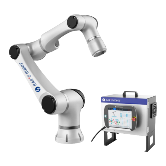
- Page 1 Collaborative Robot Elfin Series Electrical installation (E03/E05/E10)...
- Page 2 Security Configuration: It introduces the basic safety settings. Technical Support Shenzhen Han's Robot Co., Ltd will provide you with long-term technical services. If you have any technical problems or other needs during using our robot, you are welcome to visit our company website: www.hansrobot.com, or directly contact our technical engineers.
-
Page 3: Table Of Contents
www.hansrobots.eu INDEX CHAPTER 1 ELECTRICAL INTERFACES..............1 ........................1 RECAUTIONS ....................2 1.1 C ONNECTING CABLE ..........3 1.2 E XTERNAL NTERFACE AND ONNECTION NSTRUCTIONS 1.3 I I/O................. 5 NTRODUCTION TO ONTROLLER 1.4 G I/O............6 ENERAL SPECIFICATION FOR ALL DIGITAL I/O......................7 AFETY ................8 EFAULT ECURITY ONFIGURATION... -
Page 4: Chapter 1 Electrical Interfaces
www.hansrobots.eu Chapter 1 Electrical Interfaces This chapter describes all the electrical interfaces of the robot arm and the control box. These interfaces are divided into five categories, each of which has different uses and attributes: Controller I/O Tool I/O Ethernet Power connection Robot connection “I/O”The term refers to the digital and analog control signals coming in and out of... -
Page 5: Connecting Cable
www.hansrobots.eu Connecting cable As shown in the below figure, the line is the power cable of the electric control box. The cable line is 5m long. The control box must be connected to the power supply. This process must be completed using the corresponding IEC C13 wire connected to the standard IEC C14 plug on the bottom of the control box. -
Page 6: External Interface And Connection Instructions
www.hansrobots.eu External Interface and Connection Instructions Front: Name Carrying handle Exhaust vent Air inlet Cabinet keyhole Screw fixed foot rack fixed plate of teaching pad Bottom:: Name Robot connector Teach pendant connector Controller power switch AC power socket grommet... - Page 7 www.hansrobots.eu The controller connects the teach pendant: The controller connects the robot: Fasten the controller:...
-
Page 8: Introduction To
www.hansrobots.eu Introduction to Controller I/O The controller provides a series of external interfaces, for connecting controller I/O with various devices such as external relays, PLC, sensors and emergency stop device. The port layout of the controller panel I/O is shown below:... -
Page 9: General Specification For All Digital I/O
www.hansrobots.eu General specification for all digital I/O This section describes the electrical specifications of 24V digital I/O provided by the controller. (Type:PNP) General I/O (Type:PNP) Safety I/O (Type:PNP) Configurable I/O The digital I/O power supply is provided internally by the controller, and can be supplied externally when needed. -
Page 10: Safety I/O
www.hansrobots.eu The digital I/O follows the requirements of IEC61131-2. The electrical specifications are as follows. minimum Typical Maximum Terminal parameter unit value value value Digital output COx / DOx Current COx / DOx Voltage drop COx / DOx Leakage current COx / DOx Function Type... -
Page 11: Default Security Configuration
www.hansrobots.eu Danger Don’t connect the safety signal with non-safe PLC. Failure to comply with this warning may lead to casualty accidents due to failure of safety functions. Be sure to separate safety signals from the normal I/O port signal. All the Safety I/O are redundant (two independent channels). Keep two channels independent to ensure that the safety function will not fail when one channel fails. -
Page 12: Connect The E-Stop Button
www.hansrobots.eu Connect the e-stop button The external connection diagram of one or more e-stops is shown below: Emergency stop reset function... -
Page 13: Safe Emergency Stop With Other Machines
www.hansrobots.eu Safe emergency stop with other machines Safety Protection Stop Taking the door switch as an example, the following diagram introduces the construction of basic protection stop function, when the door is opened, robot stops. -
Page 14: Protective Stop With Reset
www.hansrobots.eu Protective stop with reset When the protective stop is triggered, the following double channel buttons can be reset or reset through the trainer software. The corresponding construction method is as follows. -
Page 15: Build A General Digital I/O
www.hansrobots.eu Build a General Digital I/O The general digital I/O must follow the general configuration of digital I/O. The flexible I/O, which is not used for safety functions, can be used as general digital I/O. The use of digital output: Control digital input with button:... -
Page 16: General Analog I/O
www.hansrobots.eu General Analog I/O Used to set or measure voltage (0-10v) or current (4-20ma) between devices. To achieve high precision, please follow the following rules in use: Use the closest GND to I/O. The measuring equipment and the controller use the same ground (GND), and the analog I/O is not isolated from the controller. -
Page 17: Using Analog Output
www.hansrobots.eu Using analog output The following example shows how to use analog output to control the speed of conveyor belt. Using analog input The diagram below shows how to connect the analog sensors. -
Page 18: Remote Switch Control
www.hansrobots.eu Remote switch control With Power IO, the control box can be turned on and off without going through the teach pendant. The construction method is as followed: Power on: contact trigger; Power off: keep the short connection at 2.5s-3 S Safety Guardrail Users should conduct a risk assessment for specific robot applications to determine whether to install security guardrails in the actual operating environment. -
Page 19: Robot Terminal Io Interface Description
www.hansrobots.eu Robot Terminal IO Interface Description 1、IO external wiring harness is defined as follows: Connector plug Line color definition signal description Digital input 0 INPUT_0 Brown Digital input 1 INPUT_1 blue Digital input 2 INPUT_2 White Digital output 0 OUTPUT_0 green Digital output 1 OUTPUT_1... - Page 20 www.hansrobots.eu Internal power supply specifications: parameter Typical value unit 24V power supply voltage 24V power supply current If the current exceeds its limit, the software will protect and shut down the output, and the internal control system will generate an error message and display it in the robot log;...
- Page 21 www.hansrobots.eu Digital input (PNP) Digital Input parameter terminal Typical value Unit Voltage OFF area ON area Current (11-30V) Features Type IEC 61131-2 Type The digital inputs are equipped with weak pull-down resistors. This means that the reading of the floating input is always low. Example of using a digital input:...
- Page 22 www.hansrobots.eu Analog input parameter Typical value unit Input voltage range Input resistance Ω The analog input of the tool uses a non-differential input. Any change in the current of the common grounding connector may cause an interference signal to the analog input. It is important to know that there will be a voltage drop on the ground line and inside the connector.
-
Page 23: Chapter 2 Teach Pendant
www.hansrobots.eu Chapter 2 Teach pendant As shown in the figure below, Elfin's handheld teach pendant, the button on the left is the power-on button of the robot, and the button on the right is the emergency stop button;... -
Page 24: Chapter 3 The Process Of Starting The Robot
www.hansrobots.eu Chapter 3 The process of starting the robot Connect the handheld teach pendant: Connect the interface of the handheld teach pendant to the 2-port (bottom of the electrical control box) shown below: Connect the electric control box power supply: Plug the 4 interface of the following figure into the power cable of the electric control box, and connect the other end of the power cable to the 220V power supply;... - Page 25 www.hansrobots.eu Press the power switch 3 of the electric control box, then press the power button on the left side of the handheld teach pendant to power on the electric control box. During the power-on of the electric control box, the robot is also powered on, and the HansRobot software starts automatically.
Need help?
Do you have a question about the Elfin Series and is the answer not in the manual?
Questions and answers