
Related Manuals for Han's Robot Elfin E03


Summary of Contents for Han's Robot Elfin E03
- Page 1 www.hansrobots.eu Collaborative Robot Elfin Series Hardware Installation (E03/E05/E10) V2.0.0...
-
Page 2: Introduction
Security Configuration: It introduces the basic safety settings. Technical Support Shenzhen Han's Robot Co., Ltd will provide you with long-term technical services. If you have any technical problems or other needs during using our robot, you are welcome to visit our company website: www.hansrobot.com, or directly contact our technical engineers. -
Page 3: Table Of Contents
www.hansrobots.eu TABLE OF CONTENTS INTRODUCTION......................II .....................II OW TO ANUAL ......................II ECHNICAL UPPORT ....................II ONTACT NFORMATION CHAPTER 1 PRODUCT INTRODUCTION..............1 ..........1 1.1 I NTRODUCTION TO OLLABORATIVE OBOT LFIN ERIES ......................1 1.2 L IST OF ARTS ......................2 1.3 R OBOT ..................2 1.3.1 AME OF (E03)..............3... - Page 4 www.hansrobots.eu (E03/E05 R ).............. 19 3.4 F IXING THE OBOT OBOT (E03/E05 R )..... 20 3.5 I NSTALLING OOLS TO THE ERMINAL OF OBOT OBOT (E10 R )..............21 3.6 F IXING THE OBOT OBOT (E10 R )......22 3.7 I NSTALLING OOLS TO THE ERMINAL OF...
-
Page 5: Chapter 1 Product Introduction
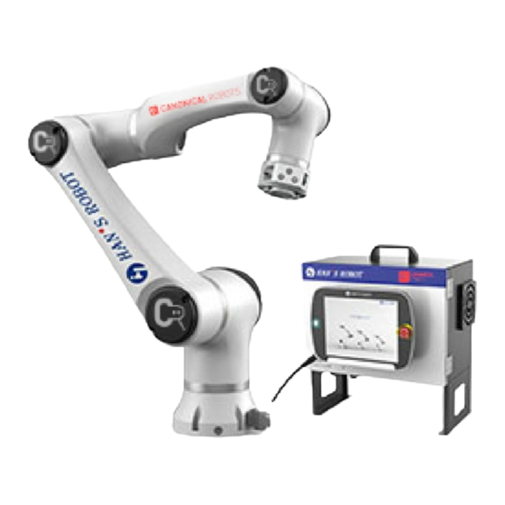
www.hansrobots.eu Chapter 1 Product Introduction Introduction to Collaborative Robot Elfin Series Elfin robot is a new type of human-machine collaborative six-axis robot. Its overall design is lightweight, modular, compact and beautiful, and it can flexibly accommodate to all kinds of complicated and varying industrial production environments. List of Parts Robot body ×1... -
Page 6: 1.3 Robot Body
www.hansrobots.eu 1.3 Robot Body 1.3.1 Name of Each Part Base Upper arm Communication and power cable J5-J6 module JI-J2 module Tool IO Lower arm Tool flange J3-J4 module... -
Page 7: Size And Specification(E03
www.hansrobots.eu 1.3.2 Size and Specification(E03)... -
Page 8: Size And Specification(E05
www.hansrobots.eu 1.3.3 Size and Specification(E05)... -
Page 9: Size And Specification(E10
www.hansrobots.eu 1.3.4 Size and Specification(E10)... -
Page 10: Robot Working Space
www.hansrobots.eu 1.3.5 Robot Working Space The working space of robot refers to the area within the specified range around the joint of robot base (as shown in the following table). When selecting the location to install robot, considerations should be given to the cylinder space above and below the robot. Please try to keep the tool away from the cylindrical space as much as possible, otherwise it will cause the situation where the tool moves slowly and joints move too fast, which leads to the low efficiency of robot and difficult risk assessment. -
Page 11: Tool Payload Range
www.hansrobots.eu 1.3.6 Tool Payload Range Due to different distances between load center at the end of robot and the center of installed flange, the allowable maximum payload of robot will change accordingly. The relationship between the centroid distance and allowable payload is shown as below:... - Page 12 www.hansrobots.eu...
-
Page 13: 1.4 Electric Control Box
www.hansrobots.eu 1.4 Electric Control Box Size and Specification... - Page 14 www.hansrobots.eu Specification of electric control box: Item Specification Weight 18.5Kg Working temperature range 0~50ºC Size 445.2*236.5*536mm Paint color Dark gray + white External power input 200-240V AC,50-60Hz...
-
Page 15: Chapter 2 Safety Issue
www.hansrobots.eu Chapter 2 Safety Issue Warning Signs This manual will use the following safety signs at different levels: Danger Failure to follow the instructions may result in serious injury and even death. Warning Failure to follow the instructions may result in personal injury or severe equipment damage. -
Page 16: General Safety Reminder
www.hansrobots.eu General Safety Reminder Some of the potentially dangerous situations are listed according to different safety levels, and the rest of which are detailed in the chapters. Danger : The operator must check robot and all electrical appliances in accordance with the instructions and warnings in Chapter 3 Mechanical Installation and Chapter 4 Electrical Ports. - Page 17 www.hansrobots.eu Pay attention to the movement of robot when using Teach Pendant. Don’t enter the safety scope of the robot or touch the robot when the system is running. Any collision will release a large amount of kinetic energy, which is much stronger than the kinetic energy of high-speed and overloading operations.
-
Page 18: Other Potential Risks
www.hansrobots.eu Other Potential Risks Please note that certain robot devices may have other major risks: Fingers are clamped between the robot foot and base. Fingers are clamped between the two arms. Sharp edges and sharp points on the tool or tool connector stab people’s skin. -
Page 19: Risk Assessment
www.hansrobots.eu Risk Assessment Risk assessment is one of the most important tasks that the integrator must complete. Robot itself is a partially completed machine, and the safety of installed robot depends on how the robot is integrated (such as tool, obstacle and other machinery). It is recommended that the integrator should use the guidelines of ISO12100 and ISO10218-2 to carry out risk assessment. -
Page 20: Repair And Maintenance Instructions
www.hansrobots.eu Repair and Maintenance Instructions All the safety instructions in this manual must be strictly observed when performing maintenance and maintenance work. Danger : Remove the main input cable from the bottom of electrical box to ensure it is completely power down; Disconnect other energy sources connected to the robot arm or electrical control box, and take the necessary precautions to prevent others from reconnecting the system energy during the maintenance. -
Page 21: Chapter 3 Mechanical Installation
www.hansrobots.eu Chapter 3 Mechanical Installation Open the Carton Step 1 Open the carton and check whether the goods inside are consistent with the items on the packing list. If there is any loss or redundant, please contact the local sales office in time. -
Page 22: Installation Environment Requirements
www.hansrobots.eu Installation Environment Requirements The robot should be installed indoors and meet the following requirements: Room temperature of 0-50℃ (to prevent excessive temperature change). Relative humidity of 10-80% (no condensation). Avoid direct sunlight. Keep it away from dust, soot, salt, metal powder and water. Avoid shock and vibration. -
Page 23: Fixing The Robot(E03/E05 Robot
www.hansrobots.eu Fixing the Robot(E03/E05 Robot) Please use 6 M6 bolts (in accordance with ISO898-1 performance level 10.9 or 12.9) to fasten the robot onto the mounting base, and tighten screws with the torque of 15Nm. No installation platform is provided when you purchase the robot, please make it by yourself or buy a robot installation platform. -
Page 24: Installing Tools To The Terminal Of Robot (E03/E05 Robot
www.hansrobots.eu The installation dimensions of the robot base are shown in the following figure, and the measuring unit is mm. Installing Tools to the Terminal of Robot ( E03/E05 Robot) No end-effector is provided when you purchase the robot, please make it by yourself or buy an end-effector. -
Page 25: Fixing The Robot(E10 Robot
www.hansrobots.eu Fixing the Robot(E10 Robot) Please use 8 M8 bolts (in accordance with ISO898-1 performance level 10.9 or 12.9) to fasten the robot onto the mounting base, and tighten screws with the torque of 35Nm. No installation platform is provided when you purchase the robot, please make it by yourself or buy a robot installation platform. -
Page 26: Installing Tools To The Terminal Of Robot(E10 Robot
www.hansrobots.eu The installation dimensions of the robot base are shown in the following figure, and the measuring unit is mm. Installing Tools to the Terminal of Robot(E10 Robot) No end-effector is provided when you purchase the robot, please make it by yourself or buy an end-effector. -
Page 27: Chapter 4 Quality Warranty
www.hansrobots.eu Chapter 4 Quality Warranty Product Quality Warranty In the principle of no prejudice to any claim agreement that may be reached between users (customers) and distributors or retailers, the manufacturer shall give customers a product quality warranty according to the following terms: If any defect occurs due to defective manufacturing or materials within 12 months after new equipment and its components are put into operation (not more than 15 months if transportation time is included), Han ’... -
Page 28: Disclaimer
www.hansrobots.eu Disclaimer Han’s Robot reserves the right to upgrade products without prior notice because it devotes itself to continual improvement on product reliability and performance. Han’s Robot does its best to ensure the accuracy and reliability of the contents of this manual, but disclaim any liability for any error or missing information. -
Page 29: Chapter 5 Appendix
www.hansrobots.eu Chapter 5 Appendix Technical Specifications E03 Robot Name Parameter 17kg Weight Payload 590mm Reach +/-360° Joint range 135°/s Joint speed 1m/s Tool +/- 0.05mm Repeatability Φ 156mm Installation area 6 rotating joints Degree of freedom 445.2*236.5*536mm Control box dimensions Digital input 3 Digital Output 3 I/O ports... - Page 30 www.hansrobots.eu IP54 IP class About 100W Power 10 advanced security configuration functions Collaboration Aluminum alloy Main material 0-50° Operating ambient temperature 200~240vac 50~60Hz External power input Control box connecting cable:5m Cables Demonstrator connecting cable:5m...
- Page 31 www.hansrobots.eu E05 Robot Parameter Name 23kg Weight Payload 800mm Reach +/-360° Joint range 135°/s Joint speed 1m/s Tool +/- 0.05mm Repeatability Φ 156mm Installation area 6 rotating joints Degree of freedom 445.2*236.5*536mm Control box dimensions Digital input 3 Digital Output 3 I/O ports Analog input 2 Digital Input 16...
- Page 32 www.hansrobots.eu Aluminum alloy Main material 0-50° Operating ambient temperature 200~240vac 50~60Hz External power input Control box connecting cable:5m Cables Demonstrator connecting cable:5m...
- Page 33 www.hansrobots.eu E10 Robot Parameter Name 40kg Weight 10kg Payload 800mm Reach +/-360° Joint range 135°/s Joint speed 1m/s Tool +/- 0.05mm Repeatability Φ 156mm Installation area 6 rotating joints Degree of freedom 445.2*236.5*536mm Control box dimensions Digital input 3 Digital Output 3 I/O ports Analog input 2 Digital Input 16...
- Page 34 www.hansrobots.eu Aluminum alloy Main material 0-50° Operating ambient temperature 200~240vac 50~60Hz External power input Control box connecting cable:5m Cables Demonstrator connecting cable:5m...
-
Page 35: Limiting Security-Related Functions
www.hansrobots.eu Limiting Security-Related Functions Limiting Safety Function Description Joint position Min. and Max. joint angular positions Joint speed Max. joint angular speed Plane where the TCP position of the robot is limited TCP position in Cartesian space TCP speed Max. speed of robot TCP TCP force Max. - Page 36 www.hansrobots.eu Class 1 stop: The robot stops when you stop it for power supply to it. The power supply is cut off after the robot stops. This is a controlled stop. The robot will follow a route compiled in the program.
Need help?
Do you have a question about the Elfin E03 and is the answer not in the manual?
Questions and answers