
Related Manuals for Lucent Technologies FT-2000 OC-48

Summary of Contents for Lucent Technologies FT-2000 OC-48
- Page 1 FT-2000 OC-48 Lightwave System Releases Through 7.2 User/Service Manual — Volume I 365-575-102 Issue 8.0 July 2002...
- Page 2 The information in this document is subject to change without notice. Although every effort has been made to make this document as accurate, complete, and clear as possible, Lucent Technologies Inc. and its predecessors assume no responsibility for any errors that may appear in this document.
- Page 3 The Lucent Technologies Regional Technical Assistance Center (RTAC) provides a technical assistance telephone number that is monitored 24 hours a day. For technical assistance, call 1-800-225-RTAC. You can also call this telephone number to provide comments on FT-2000 OC-48 Lightwave System or to suggest enhancements.
- Page 5 FT-2000 OC-48 Lightwave System Releases Through 7.2 365-575-102 Issue 8 Date: July 2002 Lucent Technologies welcomes your comments on this information product. Your opinion is of great value and helps us to improve. Was the information product: applicable In the language of your choice? In the desired media (paper, CD-ROM, etc.)?
- Page 7 Contacting NARTAC NARTAC services CTS services liii A technical support platform liii How to Order Documents How to Comment on the FT-2000 OC-48 Lightwave System Commenting on this Document Introduction Customer comment form Address for Comments Issue 8.0 July 2002...
- Page 8 Contents Electronic Documentation Product Change Notifications System Introduction Overview Introduction to the Lucent Technologies 2000 Product Family What Is the FT-2000 OC-48 Lightwave System? Applications Overview Network Configurations Two-Fiber Bidirectional Line-Switched Rings Folded Rings (Point-to-Point) End-to-End Interface Mixing OC-48 Hubbing...
- Page 9 FT-2000 OC-48 Add/Drop-Rings Terminal (E-Bay) Equipment Packages Shelf Descriptions FT-2000 OC-48 Repeater (R-Bay) 3-32 Equipment Packages 3-32 Shelf Descriptions 3-35 Upgrades 3-44 FT-2000 OC-48 Dual ADR Terminal (D-Bay) 3-45 Equipment Packages 3-45 Shelf Descriptions 3-47 Power Overview General Power Distribution Power Dissipation LEDs Issue 8.0...
- Page 10 Contents Control, Transmission, and Synchronization Interfaces Overview Control Transmission FT-2000 OC-48 Add/Drop-Rings Terminal FT-2000 OC-48 Repeater Bay Synchronization Modes 5-10 Platform Synchronization 5-10 Network Synchronization 5-19 Operations Interfaces Overview Craft Interface Terminal General PC with FT-2000 CIT-PC Software PC with CPro-2000 Software...
- Page 11 Contents Message-Based Operations System Interface 6-23 Orderwire Interface 6-30 Circuit Pack Descriptions Overview General Circuit Pack and Software Compatibility Control SYSCTL (LAA23, LAA23B, and LAA23C) Circuit Pack Description SYSMEM (LAA25) Circuit Pack Description 7-11 LNCTL (LAA28) Circuit Pack Description 7-17 OHCTL (TERM) (LAA21 and LAA22) Circuit Pack Description 7-21...
- Page 12 Contents Administration and Provisioning Overview Administration Memory Administration Version Recognition Security Software Upgrades Cross-Connections 8-11 Access Identifiers 8-93 Provisioning 8-98 Provisionable Parameters and Original Values 8-98 Local Provisioning 8-109 Pre-provisioning Circuit Packs 8-143 Provisioning on Circuit Pack Replacement 8-143 Circuit Pack Slot and Low-Speed Port Provisioning States 8-144 Maintenance Description...
- Page 13 Contents High-Speed (OC-48) 9-73 Tests 9-74 Auto Turnup 9-74 Operations Interface Tests 9-78 Circuit Provisioning Audits 9-79 Performance Monitoring 9-81 SONET Performance Parameters 9-81 OC-48 Optical Parameters 9-83 OC-3/OC-12 Optical Parameters 9-84 STS-48/STS-12/STS-3 Section Parameters 9-85 OC-48/OC-12/OC-3 Line Parameters 9-86 STS-1 Path Parameters 9-87 EC-1 Section/Line Parameters...
- Page 14 FT-2000 OC-48 Lightwave System with Wavelength Division Multiplexing and FT-LBA Systems 10-13 Transmission Distances 10-14 FT-2000 OC-48 Lightwave System without Optical Amplifiers 10-14 FT-2000 OC-48 Lightwave System and the FT-Lightwave Booster Amplifier 10-15 FT-2000 OC-48 Lightwave System with Wavelength Division Multiplexing and FT-LBA Systems...
- Page 15 Contents OC-3 Line Loss Budgets 10-20 IS-3 Access 10-22 Optical Line Interface 10-22 Optical Connector Interfaces 10-22 Transmission Medium 10-22 Lightguide Jumpers 10-22 Optical Source 10-22 Optical Detector 10-22 Optical Safety (BRH Classification) 10-23 Operating Wavelength 10-23 Spectral Width 10-23 Optical Dispersion 10-23 IS-3 Line Loss Budgets...
- Page 16 Contents Environmental Specifications 10-38 Craft Interface Terminal 10-39 Personal Computer Requirements 10-39 ASCII-Based Terminal Requirements 10-41 Modem Requirements 10-41 Operations Interfaces 10-42 TL1/X.25 Interface 10-43 General 10-43 TL1 Autonomous Messaging in Release 4.1 and Earlier 10-43 Provisioning TL1 Autonomous Messages for Release 5 and Later Releases 10-44 DTE Configuration...
-
Page 17: Table Of Contents
Figures System Introduction FT-2000 OC-48 Add/Drop-Rings Terminal for Two-Fiber Rings Applications Two-Fiber Bidirectional Ring Application Folded Ring Application Folded Rings Evolving to Full Ring Networks End-to-End Interface Mixing Application OC-48 Hubbing Application 2-10 Dual Ring Interworking Application 2-13 Dual Ring Interworking Application with the... - Page 18 2-23 Gateway Network Element Application (Release 6 and Later) 2-47 Platform Descriptions FT-2000 OC-48 Add/Drop-Rings Terminal for Two-Fiber Rings (E-Bay) Power Distribution and Fuse Panel Low-Speed Shelf — System Controller (Without Circuit Pack Cover)— ED6G999-31, G5 Low-Speed Shelf — System Controller (Without Circuit Pack Cover) —...
- Page 19 Repeater Shelf — System Controller (Without Circuit Pack Cover) 3-36 3-21 Interconnection Panel (Repeater Shelf — System Controller) 3-39 3-22 User Panel (FT-2000 OC-48 Repeater Shelf) for Miscellaneous Mounting Only 3-41 3-23 Repeater Shelf — System Controller with Covers (FT-2000 OC-48 Repeater Bay) 3-42 3-24 Repeater Shelf —...
- Page 20 Synchronization Interfaces System Control Architecture for the FT-2000 OC-48 Add/Drop-Rings Terminal System Control Architecture for the FT-2000 OC-48 Repeater Bay FT-2000 OC-48 Add/Drop-Rings Terminal for 2-Fiber Rings Transmission Block Diagram FT-2000 OC-48 Repeater Bay Transmission Block Diagram Free Running Synchronization...
- Page 21 Figures 5-19 Example of a Ring Application with One Node Provisioned Externally Timed and All Other Nodes Provisioned Line Timed (Without Timing Drops) 5-32 5-20 Example of a Ring Application with Two Nodes Provisioned Externally Timed and All Other Nodes Provisioned Through Timed or Externally Timed (Without Timing Drops) 5-33...
- Page 22 User Panel (Low Speed Shelf - System Controller and Repeater Shelf - System Controller) — Plug-In-Type (After 06/97) 6-14 User Panel (FT-2000 OC-48 Repeater Shelf) 6-16 Filter Panel for the Enhanced High Speed Shelf 6-17 Power Indicating Panel for the Condensed High Speed...
- Page 23 TG3 (DS1) (LAA18) Circuit Pack 7-116 7-35 TG3 (DS1) (LAA18) Circuit Pack Block Diagram 7-119 Administration and Provisioning STS-3 1-Way Cross-Connections at an FT-2000 OC-48 Add/Drop-Rings Terminal 8-14 STS-3 1-Way Cross-Connections at an FT-2000 OC-48 Add/Drop-Rings Terminal (1+1 Protected Slots) 8-15...
- Page 24 Figures STS-3 1-Way-DRI Cross-Connections at an FT-2000 OC-48 Add/Drop-Rings Terminal 8-20 STS-3 2-Way Cross-Connections at an FT-2000 OC-48 Add/Drop-Rings Terminal 8-22 Limited STS-1 Cross-Connections Across and STS-3 Tributary 8-25 STS-1 1-Way Cross-Connections at an FT-2000 OC-48 Add/Drop-Rings Terminal 8-29 1-Way Cross-Connections at an FT-2000 OC-48...
- Page 25 Signals (When Interfacing With EC-1, OC-3, IS-3 and OC-12 Signals) FT-2000 OC-48 Add/Drop-Rings Terminal Maintenance Signals for Through Tributaries FT-2000 OC-48 Repeater Bay Maintenance Signals 2-Fiber Ring Protection Switching Architecture (FT-2000 OC-48 Add/Drop-Rings Terminal) 9-33 Bidirectional Line-Switched 2-Fiber Ring (Normal...
- Page 26 9-20 Dual Ring Interworking Circuit (Primary Node Failure) 9-63 9-21 Dual Ring Interworking Circuit (Secondary Node Failure) 9-64 9-22 TG3 (DS1) Circuit Pack Protection (FT-2000 OC-48 Add/Drop-Rings Terminal) 9-66 9-23 DS1 Reference Protection 9-69 9-24 OC-48 Line Reference Protection (FT-2000 OC-48...
- Page 27 Circuit Packs and Compatible Software Overhead Bytes 7-24 Overhead Bytes 7-30 Section Overhead Bytes 7-34 FT-2000 OC-48 Repeater Bay Input Values 8-97 FT-2000 OC-48 Repeater Bay Output Values 8-97 Provisionable Threshold Crossing Alert (TCA) Parameters 8-106 Provisionable Parameters (FT-2000 OC-48 Repeater Bay)
- Page 28 10-9 10-6 OC-48 Loss Budget Specifications for 839B5 and 839E5 OC48 RCVR Circuit Packs 10-9 10-7 FT-2000 OC-48 Lightwave System and FT-Lightwave Booster Amplifier Loss Budgets 10-11 10-8 FT-2000 OC-48 Lightwave System and Wavelength Division Multiplexing Systems Loss Budgets 10-12...
- Page 29 Tables 11-4 Release 5 Inputs (Commands) Menu for FT-2000 Add/Drop-Rings Terminal 11-16 11-5 Release 4 Inputs (Commands) Menu for FT-2000 Add/Drop-Rings Terminal 11-20 11-6 Release 3 Inputs (Commands) Menu for FT-2000 Add/Drop-Rings Terminal 11-23 11-7 Releases 2, 4, and 6 Inputs (Commands) Menu for FT-2000 Repeater Bay/Shelf 11-25 11-8...
- Page 30 Tables Issue 8.0 July 2002...
- Page 31 Manual for Releases 1 through 7.2. Intended Audiences This user/service manual is primarily for end users responsible for operating and maintaining the FT-2000 OC-48 Lightwave System. It may be used by anyone desiring specific operation and maintenance information. xxxi Issue 8.0...
- Page 32 About This Document Reason for Reissue This document, Issue 8.0, replaces the FT-2000 OC-48 Lightwave System, Releases 1 through 7.2.8, User/Service Manual , Addendum Issue 7.2C. NOTE: This document contains change bars to identify where there has been new information added and where obsolete information has been deleted.
- Page 33 Volume I, Section 6, "Operations Interfaces," describes the interfaces that allow access to the FT-2000 OC-48 Lightwave System and provides alarm and status information. Volume I, Section 7, "Circuit Pack Descriptions," provides a detailed circuit description of each FT-2000 OC-48 Lightwave System circuit pack.
- Page 34 About This Document Volume I, Section 11, "Craft Interface Terminal Usage," describes how the craft interface terminal is used and shows the FT-2000 OC-48 Lightwave System inputs (commands), output messages, and reports. It also includes a tutorial on the use of the craft interface terminal.
- Page 35 About This Document Lightwave Safety Guidelines General Laser Information The FT-2000 OC-48 Lightwave System and associated optical test sets use semiconductor laser transmitters that emit light at wavelengths between approximately 800 nanometers (nm) and 1600 nm. The emitted light is above the red end of the visible spectrum, which is normally not visible to the human eye.
- Page 36 Also, covers are in place over the circuit pack shelves. Lightwave Safety Precautions Under normal operating conditions, the FT-2000 OC-48 Lightwave System is totally enclosed and presents no risk of eye injury. It is a Class I system under the FDA/CDRH scheme.
- Page 37 About This Document Safety Precautions for Enclosed Systems Under normal operating conditions the FT-2000 OC-48 Lightwave System is completely enclosed; nonetheless, the following precautions should be observed: Because of the potential for eye damage, technicians should neither disconnect any lightwave cable nor splice and stare into the optical connectors terminating the cables.
- Page 38 Figure 2. Compliance Label Safety Precautions for Unenclosed Systems During service, maintenance, or restoration, the FT-2000 OC-48 Lightwave System is considered unenclosed. During service, maintenance, or restoration, observe the following precautions: Only authorized, trained personnel should be permitted to do service, maintenance, and restoration.
- Page 39 About This Document exposure distance. However, technicians removing or replacing regenerators should not stare or look directly into the vacant regenerator slot with optical instruments or magnifying lenses. (Normal eyewear or indirect viewing instruments, such as Find-R-Scope are not considered magnifying lenses or optical instruments.) Only authorized, trained personnel should use the lightwave test equipment during installation or servicing, since this equipment contains...
- Page 40 About This Document Always store and transport circuit packs in static-safe packaging. Shielding is not required unless specified. Keep all static-generating materials such as food wrappers, plastics, and styrofoam * containers away from all circuit packs. When removing circuit packs from a bay, immediately place the circuit packs in static-safe packages.
- Page 41 About This Document Security Lucent Technologies has designed the craft interface terminal (CIT) so that, when properly administered, it will minimize the ability of unauthorized persons to gain access to the network. Each authorized user should be instructed about the proper use of the CIT.
- Page 42 Use only Lucent Technologies manufactured, recognized circuit packs. Refer to 365-575-104, FT-2000 OC-48 Lightwave System, Releases 1 and 2, Installation Manual , and 365-575-115, FT-2000 OC-48 Lightwave System, Releases 4, 5, 6, and 7 Installation Manual , for a list of recognized circuit packs.
- Page 43 Content: Abbreviated list of common report commands and a trouble clearing procedure that can be used to clear most trouble Number: 365-575-115 Title: FT-2000 OC-48 Lightwave System, Releases 3 Through 8 Installation Manual Audience: Customers planning to install and turn up the equipment...
- Page 44 Job Aid (Releases 4, and Higher) Audience: End user maintenance personnel Content: List of provisionable TCA parameters, original values, and the corresponding inputs for the FT-2000 OC-48 Add/Drop-Rings Terminal Number: 365-575-124 Title: FT-2000 Cross-Connections Job Aid (Releases 8.1 and Later)
- Page 45 Content: Operations Interworking information for Lucent’s 2000 Product Family systems, including DDM-2000 OC-3 R13.0, DDM-2000 OC-12 R7.0, FiberReach R3.0, and FT-2000 OC-48 R8.1 and later, as well as Lucent’s 3000 Product Family systems, including WaveStar BandWidth Manager R2.0, WaveStar 2.5G R3.0, and WaveStar 10G R1.0 in Multi- Vendor subnetworks.
- Page 46 Title: Modification Implementation Procedure 0046-MV, FT-2000 Add/Drop Ring Terminal DCC Cable Upgrade . Audience: RTAC, Installers, Engineers, Planners Content: Convert an in-service FT-2000 OC-48 ADR Terminal J68974, L3 or equivalent to an ADR Terminal with OC-3 Data Communications Channel (DCC) capability, J68974, L5 or equivalent xlvi Issue 8.0...
- Page 47 About This Document Lucent Technologies Drawings The following Lucent Technologies drawings provide information about the FT- 2000 OC-48 Lightwave System: FT-2000 OC-48 Lightwave Terminating Bay (Circuit J68974AK-1 Packs, Miscellaneous Hardware, and Spare Parts Shipped Separately from Equipment) J68974D-1 FT-2000 OC-48 Dual Lightwave Terminating...
- Page 48 Cable Assemblies for ED-7G001-30 OC-48 Lightwave Terminating Bay ED-7G001-24 Cable Assemblies for ED-7G001-31 OC-48 Enhanced Lightwave Terminating Bay FT-2000 OC-48 Coaxial Cable Assemblies for All EC-1/ ED-7G001-21 DS3 Applications (Intraoffice Transmission Cables) ED-7G001-22 FT-2000 OC-48 Interbay Cable Assemblies (Intraoffice Non-Transmission Cables)
- Page 49 About This Document FPD 804-911-168-3 FT-2000 Lightwave Transmission System OC-48 Enhanced Lightwave Terminating Bay with 2 Active Shelves on Nonseismic Framework FPD 804-911-168-4 FT-2000 Lightwave Transmission System OC-48 Enhanced Lightwave Terminating Bay with 3 Active Shelves on Nonseismic Framework FPD 804-911-168-5 FT-2000 Lightwave Transmission System OC-48 Enhanced Lightwave Terminating Bay with 2 Active Shelves on Seismic Framework...
- Page 50 About This Document Lucent Technologies Practices for Related Equipment The following Lucent Technologies documents provide information about related equipment: Seismic Network Bay Frame Application, Planning, and 065-215-200 Ordering Guide 065-215-250 Seismic Network Bay Frame Installation Guide Guide to Using CPro-2000...
- Page 51 Suitcasing of these courses is also available. To enroll in a training class at one of the Lucent Technologies corporate training centers, please call 1-888-LUCENT8 (1-888-582-3688): Prompt 2. To arrange a...
- Page 52 About This Document Technical Support Introduction This section describes the technical support available for FT-2000 OC-48 Lightwave System. Technical support groups Technical support is available through the following: North American Regional Technical Assistance Center (NARTAC) Customer Technical Support (CTS) Lucent Technologies technical support groups are committed to providing customers with high-quality product support services.
- Page 53 About This Document Writes technical bulletins Provides technical assistance to installers NARTAC personnel are supported by the Lucent Technologies Customer Technical Support (CTS) organization. CTS services The CTS organization provides quality product support services and regards the customer as its highest priority. The CTS organization maintains direct contact with development and manufacturing organizations of Lucent Technologies to assure prompt resolution of all customer assistance requests.
- Page 54 Make checks payable to Lucent Technologies. Lucent Technologies entities should use Form IND 1-80.80 FA, available through the Customer Information Center. One-time orders include a binder (if applicable) and the document contents for the current issue in effect at the time of order.
- Page 55 The Regional Technical Assistance Center (RTAC) technical assistance telephone number is available 24 hours a day for customers to provide feedback and enhancement suggestions for improving the FT-2000 OC-48 Lightwave System. The toll free number is 1-800-225-RTAC. Commenting on this Document...
- Page 56 About This Document Electronic Documentation Documentation for the FT-2000 OC-48 Lightwave System is now available in electronic form, on compact disk, read-only memory (CD-ROM). CD-ROM has many advantages over traditional paper documentation, including cost savings, search and retrieve capability, and the assurance of the most current documentation.
-
Page 57: System Introduction
System Introduction Table of Contents Overview Introduction to the Lucent Technologies 2000 Product Family What Is the FT-2000 OC-48 Lightwave System? Issue 8.0 July 2002... - Page 58 Table of Contents 1-ii Issue 8.0 July 2002...
- Page 59 The 2000 Product Family provides broadband services, a high degree of reliability, and full compatibility with industry standards. The FT-2000 OC-48 Lightwave System is the high capacity optical carrier level 48 (OC-48) lightwave system in the 2000 Product Family. The 2000 Product Family...
- Page 60 SONET OC-48 signal level of 2.5 Gb/s (up to 32,256 voice channels). The FT-2000 OC-48 Lightwave System consists of several platforms. A platform is a family of equipment and software configurations designed to support a particular set of applications.
-
Page 61: Oc-48 Add/Drop-Rings Terminal For Two-Fiber Rings
Low Speed Shelf - 84" OC3, OC3, IS3, IS3, System Controller and/or and/or OC12 OC12 4" PC Tray Filter Panel Interconnection Panel 21.5" Enhanced High Speed Shelf 4" Screen 4" Figure 1-1. FT-2000 OC-48 Add/Drop-Rings Terminal for Two-Fiber Rings Issue 8.0 July 2002... - Page 62 The FT-2000 OC-48 Lightwave System will be made available in a series of phased product releases. These phased product releases will provide new sets of features. This user/service manual covers Releases 1 through 7.2 and will be updated to cover additional releases as they become available.
- Page 63 — Revertive DRI — Switching on AIS-P Expanded reporting for up to 32 Network/Subnetwork elements Release 7.2 updates the FT-2000 OC-48 Add/Drop-Rings Terminal platform with the following new features: New Low Speed Shelf/User Panel/Interconnection Panel Dense Wavelength Division Multiplexing (DWDM)—OLS-compatible...
-
Page 64: Major Features Of Product Releases 1 Through
System Introduction Table 1-1 also shows the major features of the FT-2000 OC-48 Lightwave System and the corresponding product releases. Table 1-1. Major Features of Product Releases 1 Through 7.2 Available in Product Release: Major Features Applications - Point-to-Point - Point-to-Point with Repeaters... - Page 65 - Line Timed Mode Synchronization With Auto Reconfiguration - Switch on Line Signal Degrade for DRI For more information about the FT-2000 OC-48 Lightwave System releases and their availability, refer to 365-575-100, FT-2000 OC-48 Lightwave System, Applications, Planning, and Ordering Guide .
- Page 66 System Introduction Issue 8.0 July 2002...
- Page 67 Applications Table of Contents Overview Network Configurations Two-Fiber Bidirectional Line-Switched Rings Folded Rings (Point-to-Point) End-to-End Interface Mixing OC-48 Hubbing 2-10 Dual Ring Interworking (DRI) 2-11 DDM-2000 OC-3 Ring Transport 2-17 DDM-2000 OC-12 Ring Transport 2-18 Dual-Wire Center Architecture 2-18 Broadband Service Transport —STS-3c/STS-12c 2-21 STS-1/STS-3 Non-Preemptible Protection Access 2-24...
- Page 68 Table of Contents Synchronization Messaging 2-48 2-ii Issue 8.0 July 2002...
- Page 69 Applications Overview The FT-2000 OC-48 Lightwave System satisfies a wide range of applications with maximum economy and efficiency. These applications include OC-48 point-to-point, two-fiber bidirectional line-switched rings, hubbing, DRI, dual-wire center architecture, broadband service transport, and loop feeder network applications. This section describes how the FT-2000 OC-48 Lightwave System...
-
Page 70: Applications
Volume I, Section 10, "Technical Specifications." The FT-2000 OC-48 Add/Drop-Rings Terminal typically interfaces to digital multiplexers, such as the DDM-2000 Multiplexers, to digital access and cross-connect systems such as DACS III-2000, DACS IV-2000, or Tellabs TITAN 5500/S, a digital switch, or other facilities. -
Page 71: Two-Fiber Bidirectional Ring Application
The FT-2000 OC-48 Add/Drop-Rings Terminals and FT-2000 OC-48 Dual Lightwave Terminating Bay may be equipped with Release 3.0.1-ADR or later software. In a two-fiber bidirectional ring, all FT-2000 OC-48 Add/Drop-Rings Terminals must be equipped with the same release of software. - Page 72 STS-3 tributary of the other OC-48 high-speed line (through cross-connection). In Release 7 and later, the FT-2000 OC-48 Add/Drop-Rings Terminal and FT-2000 OC-48 Dual Lightwave Terminating Bay also offer a TSA capability that allows any...
- Page 73 Applications Non-Preemptible Protection Access (NPPA) is a type of extra traffic . It increases the “service traffic” capacity of a node at the expense of reducing bandwidth on the protection fiber. However, service on corresponding tributaries will be lost (for example, tributary 9 would be preserved and tributary 1 would be lost).
- Page 74 Folded Ring Application The FT-2000 OC-48 Add/Drop-Rings Terminal equipped with Release 3.0.1 or later software or the FT-2000 OC-48 Dual Lightwave Terminating Bay may be used in folded rings. In a folded ring application, all FT-2000 OC-48 Add/Drop-Rings Terminals must be equipped with the same release of software.
-
Page 75: Folded Rings Evolving To Full Ring Networks
Site B Site C Present FT-2000* FT-2000* FT-2000* FT-2000* Site A Site B Site C Future FT-2000* FT-2000* FT-2000* Site D FT-2000* * FT-2000 OC-48 Add/Drop-Rings Terminal Figure 2-3. Folded Rings Evolving to Full Ring Networks Issue 8.0 July 2002... - Page 76 For example, the asynchronous (DS3) low-speed interfaces at one FT-2000 OC-48 Add/Drop-Rings Terminal in a network can be upgraded in service to synchronous (EC-1, IS-3, OC-3 or OC-12) low-speed interfaces without any changes at the other FT-2000 OC-48 Add/Drop-Rings Terminal terminating the circuit (Figure 2-4).
-
Page 77: End-To-End Interface Mixing Application
OC-48 Figure 2-4. End-to-End Interface Mixing Application The FT-2000 OC-48 Add/Drop-Rings Terminal supports the following combinations of low-speed interfaces concurrently between nodes in a network: Three DS3 or EC-1 signals at one end (or from various nodes) and one OC-3 signal at the other end... -
Page 78: Oc-48 Hubbing Application
Limited STS-1 cross-connections allow three DS3 or EC-1 circuits from various nodes in a network to be routed to a single destination and output as an OC-3 signal. In Release 7 and later releases, the FT-2000 OC-48 Add/Drop-Rings Terminal also has an STS-1 TSA capability that allows STS-1 cross-connections. -
Page 79: Tributary
DRI protection switching, refer to Volume I, Section 9, “Maintenance Description.” In a DRI application with two line-switched rings equipped with FT-2000 OC-48 Add/Drop-Rings Terminals, the primary node in one ring may be connected to the primary node in the other ring. For example, in Figure 2-6, Node 5 is the primary node in Ring A and Node 1 is the primary node in Ring B. - Page 80 Applications NOTE: If the primary node in one ring is connected to the secondary node in the other ring, the DRI-provisioned circuit will be protected against a failure of the low-speed cross-connected circuit. However, the DRI-provisioned circuit may not be protected if one of the DRI-provisioned nodes becomes isolated from the ring (for example, node power failure or open fibers on both sides).
-
Page 81: Dual Ring Interworking Application
Applications Node 1 Node 2 FT-2000* FT-2000* Node 0 Node 3 FT-2000* FT-2000* Ring A Node 5 Node 4 FT-2000* FT-2000* Node 1 Node 0 Node 2 Node 5 Ring B Node 3 Node 4 Figure 2-6. Dual Ring Interworking Application 2-13 Issue 8.0 July 2002... - Page 82 DS3-based EC-1 signal, then emerge from a node in the other ring in the original DS3 format. A line-switched ring equipped with FT-2000 OC-48 Add/Drop-Rings Terminals may also accept VT1.5-based EC-1 signals from a path-switched ring equipped with DDM-2000 Multiplexers.
-
Page 83: Dual Ring Interworking Application With The Ddm-2000 Oc-3 Multiplexer
DDM-2000 DDM-2000 DRI Node OC-3 Ring OC-3 (or OC-12) Loop Feeder DDM-2000 DDM-2000 OC-3 OC-3 FT-2000 OC-48 Add/Drop-Rings Terminal (Release 5 and later) nc-ft2000-029 Figure 2-7. Dual Ring Interworking Application with the DDM-2000 OC-3 Multiplexer 2-15 Issue 8.0 July 2002... - Page 84 1+1 protected OC-3 interfaces. For more information about DRI protection switching, refer to Volume I, Section 9, “Maintenance Description.” If the primary node in the line-switched ring fails, the FT-2000 OC-48 Add/Drop-Rings Terminals adjacent to the primary node perform two-fiber ring protection switching.
-
Page 85: Ddm-2000 Oc-3 Ring Transport Application
OC-3 signals (OC3 1, OC3 2, OC3 3, OC3 4) connecting them. The OC-3 1 signal is transported between CO 1 and CO 2 by the FT-2000 OC-48 Add/Drop-Rings Terminals. One or more OC-48 Ring segments or rings may be used as segments of a DDM-2000 OC-3 Ring. - Page 86 Applications In Release 6 and later releases, the FT-2000 OC-48 Add/Drop-Rings Terminal provides single-ended operation capabilities through the OC-3 DCC. For more information about the single-ended operation capabilities, refer to the “Operations Interworking” application in this section. For more information about operations...
-
Page 87: Dual-Wire Center Architecture Application
DACS IV-2000 EC-1 EC-1 SERVICES SERVICES DDM-2000 DDM-2000 OC-3 OC-3 DDM-2000 OC-3 Path-Switched Ring DDM-2000 ® SLC -2000 OC-3 DDM-2000 OC-3 FT-2000 OC-48 Add/Drop-Rings Terminal (Release 5 and later) nc-ft2000-030 Figure 2-9. Dual-Wire Center Architecture Application 2-19 Issue 8.0 July 2002... - Page 88 363-206-200, DDM-2000 Multiplexer, Applications, Planning, and Ordering Guide . In Release 6 and later releases, the FT-2000 OC-48 Add/Drop-Rings Terminal provides single-ended operation capabilities through the OC-3 DCC. For more information about the single-ended operation capabilities, refer to the “Operations Interworking”...
- Page 89 Add/Drop-Rings Terminals. The FT-2000 OC-48 Add/Drop-Rings Terminals are connected to ATM service multiplexers and switches with OC-3 low-speed interfaces. The FT-2000 OC-48 Add/Drop-Rings Terminals at CO 1 and CO 2 are optical hubs that provide OC-3/OC-12 optical extensions to ATM service multiplexers.
-
Page 90: Broadband Service Transport Application
OC-3 or OC-12** OC-48 Service FT-2000 OC-48 Add/Drop-Rings Terminal (Release 5 and later) FT-2000 OC-48 Add/Drop-Rings Terminal (Release 7.1.0 or later) If an STS-12c signal is to be transported - then ALL nodes on the ring MUST be equipped with (x5 or 4x) TRMTRs nc-ft2000-032 Figure 2-10. - Page 91 SONET STS-12c signal, a combination of STS-1 and STS-3c signals, or an SDH type STM-4 signal. In Release 6 and later releases, the FT-2000 OC-48 Add/Drop-Rings Terminal provides single-ended operation capabilities through the OC-3 DCC. For more information about the single-ended operation capabilities, refer to the “Operations Interworking”...
- Page 92 Applications STS-1/STS-3 Non-Preemptible Protection Access This feature is available with FT-2000 OC-48 ADR Release 7.1 and later software. More specifically, this feature is applicable for FT-2000 OC-48 ADR Terminal ring configurations that are equipped with STS-1 granularity hardware (for example, 739 transmitter and 839B5 receiver) at all ring nodes.
- Page 93 Applications It should be emphasized that the primary need for this feature is to increase the span capacity and thus increase bandwidth efficiency for “Path-in-Line” applications. As a review, a “Path-in-Line” application carries path-switched ring traffic within the FT-2000 line-switched ring. Tributaries of the FT-2000 ring provide transport between DDM-2000 OC-3 and/or SLC-2000 ring nodes.
-
Page 94: One-Way Video Distribution Application
The FT-2000 OC-48 Add/Drop-Rings Terminal equipped with Release 5.0.1-ADR or later software can be used in 1-way video distribution applications. The FT-2000 OC-48 Add/Drop-Rings Terminal is used to distribute video signals from one or more video servers to video serving areas (Figure 2-11). - Page 95 All cross-connections in this video application are 1-way STS-3 cross-connections from the video server to the customer. Because the corresponding return path has no input signal, the FT-2000 OC-48 Add/Drop-Rings Terminal reports a trouble condition. In Release 6 and later releases, the FT-2000 OC-48 Add/Drop-Rings Terminal may be provisioned to disable reporting this trouble condition.
-
Page 96: Path-In-Line Architecture
OC-3 Path-Switched DDM-2000 DDM-2000 Ring DDM-2000 FT-2000 OC-48 Add/Drop-Rings Terminal (Release 6 and later) The grey shading indicates the extent of OC-3 ring. nc-ft2000-033 Figure 2-12. Path-In-Line Architecture The path-in-line architecture is a self-healing network architecture that provides end-to-end survivable DS1 and DS3 services. Figure 2-12 shows an OC-3 path-switched ring using part of the bandwidth of an OC-48 bidirectional line-switched ring. - Page 97 STS-1 cross-connections, and path-protection switching, refer to 363-206-200, DDM-2000 Multiplexer, Applications, Planning, and Ordering Guide . In Release 6 and later releases, the FT-2000 OC-48 Add/Drop-Rings Terminal provides single-ended operation capabilities through the OC-3 DCC. For more information about the single-ended operation capabilities, refer to the “Operations Interworking”...
-
Page 98: Loop Feeder Network Application
Applications Loop Feeder Network The FT-2000 OC-48 Add/Drop-Rings Terminal, equipped with Release 5.0.1-ADR or later software, can be used in a loop feeder network with OC-3 low-speed interfaces. Figure 2-13 shows a two-fiber ring used to connect one or more central offices to one or more DDM-2000 Multiplexers at remote sites. - Page 99 Applications The FT-2000 OC-48 Add/Drop-Rings Terminal must be located in a controlled environment facility (for example, a controlled environment vault [CEV], temperature controlled hut, or central office). Figure 2-13 shows the following OC-3 connections between the DDM-2000 Multiplexers and an FT-2000 OC-48 Add/Drop-Rings Terminal equipped with...
-
Page 100: Extra Traffic (Protection Line Access) For Restoration And Revenue Generation Application
Applications Extra Traffic for Restoration and Revenue Generation The FT-2000 OC-48 Add/Drop-Rings Terminal allows access to the idle protection STS-3 tributaries for low priority traffic or for restoration purposes. Figure 2-14 shows how the FT-2000 OC-48 Add/Drop-Rings Terminal can be used with a DACS III-2000 and/or DACS IV-2000 Cross-Connect System and the â... - Page 101 Applications Extra traffic is established by cross-connecting low-speed service slots to protection STS-3 tributaries, using the CIT (locally or remotely). For the FT-2000 ADR Releases 1 through 7, “Extra traffic” can only be established on a preemptible basis. Preemptible means that a signal fail or signal degrade condition on the service STS-3 tributaries causes traffic to be automatically switched to the protection STS-3 tributaries, preempting extra traffic.
-
Page 102: 0% Add/Drop Application
Applications 0% Add/Drop Figure 2-15 shows the FT-2000 OC-48 Add/Drop-Rings Terminal in a 0% add/drop application. In the 0% add/drop application, an FT-2000 OC-48 Add/Drop-Rings Terminal is not equipped with low speed interface circuit packs and acts as a repeater. Only 1-way and two-way through cross-connections are used at the 0% add/drop node. - Page 103 140 km using standard fiber or 160 km using dispersion-shifted fiber. This capability reduces the number of repeater sites on long routes. This capability also allows the FT-2000 OC-48 Add/Drop-Rings Terminal and FT-LBA to be used with poor fiber or fiber that has frequent, high-loss splices (for example, in urban areas) or with dispersion-shifted fiber and terrestrial electronics (for example, underwater/sea applications).
- Page 104 FT-LBA. In Release 6 and later releases, the FT-Lightwave Booster Amplifier (FT-LBA) can also be used with the FT-2000 OC-48 Repeater Bay equipped with Release 6.0.0-RPTR software to extend the distance between sites. The FT-2000 OC-48 Repeater Bay must be equipped with the OC48 Regenerator —...
-
Page 105: Wavelength Division Multiplexing Application
1.5 µm wavelength signal, enabling the two signals to operate on the same fiber pair. Thus, one FT-2000 OC-48 Lightwave System and one FT Series G 1.7 Gb/s system or two FT-2000 OC-48 Lightwave Systems at the same location, each equipped for lightwave transmission at different wavelengths, can share the same fiber pair. - Page 106 Section by Section Wavelength Division Multiplexing (1.3 µm/1.5 µm) In Release 6 and later releases, the FT-2000 OC-48 Add/Drop-Rings Terminal may be equipped with the OC48 Transmitter, Add/Drop(A/D) — 1.5µm LBA Wavelength 1 (OC48 TRMTR [A/D 1.5 LBA W1]) and the OC48 Transmitter, Add/Drop(A/D) —...
- Page 107 Wavelength Division Multiplexing Application (1.5 µm/1.5 µm) In Release 6 and later releases, the FT-2000 OC-48 Repeater Bay may be equipped with the OC48 REGENR — 1.5µm Standard Performance (OC48 REGENR [1.5 LBA W1]) and the OC48 Regenerator — 1.5 µm Standard Performance (OC48 REGENR [1.5 LBA W2]) circuit packs when using...
- Page 108 Applications Figure 2-20 shows WDM used in repeater sections with FT-LBA. FT-2000 FT-2000 OC-48 RING A OC-48 OC-48 Repeater Site CO 1 CO 2 FT-2000 FT-2000 OC-48 OC-48 OC-48 FT-2000 FT-2000 RING B OC-48 FT-2000 FT-2000 FT-2000 OC-48 OC-48 Legend: LBA = FT-LBA R = Repeater Section by Section WDM (1.5 µm/1.5 µm)
- Page 109 Applications CAUTION: In WDM applications with bidirectional OC-48 signal transmission over a single fiber, unprotected fiber or coupler failures are possible. If a fiber break or coupler failure occurs, sufficient light may be reflected from the break to the local receiver and cause the local receiver to frame on the signal transmitted by the local transmitter (optical loopback).
-
Page 110: Operations Interworking Application
Applications Operations Interworking The FT-2000 OC-48 Add/Drop-Rings Terminal equipped with Release 6.0.0-ADR or later software supports operations interworking applications with DDM-2000 Multiplexers (Figure 2-21). FT-2000* 0 x 1 Connection DDM-2000 FT-2000* FT-2000* OC-48 Line-Switched OC-3 Ring Path-Switched DDM-2000 Ring 0 x 1... - Page 111 (0), the DDM-2000 OC-3 Multiplexers will not show up in the CONFIGURATION-Retrieve-Map-Network report and no FT-2000 OC-48 Add/Drop-Rings Terminal can be used as a TL1 gateway network element (GNE) for the DDM-2000 OC-3 Multiplexers.
- Page 112 When Release 6 of the FT-2000 OC-48 Add/Drop-Rings Terminal interworks with Release 7.2 of the DDM-2000 OC-3 Multiplexer, an alarm group supports up to 24 NEs. When Release 7 of the FT-2000 OC-48 Add/Drop-Rings Terminal interworks with Release 7.2 of the DDM-2000 OC-3 Multiplexer, an alarm group supports up to 32 NEs.
- Page 113 For more information about software upgrades, refer to Volume I, Section 8, “Administration and Provisioning.” When Release 6 of the FT-2000 OC-48 Add/Drop-Rings Terminal interworks with Release 7.2 of the DDM-2000 OC-3 Multiplexer in subnetworks with less than 16 NEs, the same NE may serve as the TL1 GNE and the alarm GNE.
-
Page 114: Gateway Network Element Application
Applications Gateway Network Element (GNE) In Releases 4.1 and 5, the FT-2000 OC-48 Add/Drop-Rings Terminal may operate as a GNE that serves as a single interface to the local X.25 message-based operations system for all the FT-2000 OC-48 Add/Drop-Rings Terminals in a ring network. -
Page 115: Gateway Network Element Application
Terminals can serve as a single interface to the local X.25 message-based operations system for the DDM-2000 Multiplexers through the OC-3 DCC (Figure 2-23). The GNE also serves as a single interface for all FT-2000 OC-48 Add/Drop-Rings Terminals in the same ring network and in the same subnetwork. -
Page 116: Synchronization Status Messages
X.25 links between the ring network and the operations system, one FT-2000 OC-48 Add/Drop-Rings Terminal may operate as the GNE. If redundancy is desired, two or more FT-2000 OC-48 Add/Drop-Rings Terminals may operate as GNEs. For more information about provisioning a GNE, refer to Volume I, Section 8, “Administration and Provisioning.”... -
Page 117: Ft-2000 Ring Environments
Applications The message DUS (Don’t Use for Synchronization is used to indicate a link on which timing has been looped back, in order to prevent timing loops an invalid message Synchronization messages are exchanged between FT-2000 nodes over OC-48 interfaces via bits 5, 6, 7, and 8 of the S1 byte from FT-2000 nodes to DDM-2000 nodes over OC-3 and OC-12 interfaces via proprietary message set on bits 1, 2, and 3 of the K2 byte. - Page 118 Applications 2-50 Issue 8.0 July 2002...
-
Page 119: Platform Descriptions
3-32 Shelf Descriptions 3-35 Power Distribution and Fuse Panel 3-35 Repeater Shelf — System Controller 3-36 Heat Baffle 3-44 PC Tray 3-44 Screen 3-44 Upgrades 3-44 FT-2000 OC-48 Dual ADR Terminal (D-Bay) 3-45 Equipment Packages 3-45 Issue 8.0 July 2002... - Page 120 Table of Contents Shelf Descriptions 3-47 Power Distribution and Fuse Panel 3-47 Low-Speed Shelf — System Controller 3-47 Condensed High-Speed Shelf 3-57 Fan Assembly 3-63 3-ii Issue 8.0 July 2002...
- Page 121 Platform Descriptions Overview This section introduces the FT-2000 OC-48 Lightwave System platforms and provides a more detailed view of the FT-2000 OC-48 Lightwave System physical design. Introduction The FT-2000 OC-48 Lightwave System is a flexible high-capacity lightwave system that transports digitally encoded information through single-mode optical fibers at the synchronous optical network (SONET) OC-48 signal level of 2.5 Gb/s...
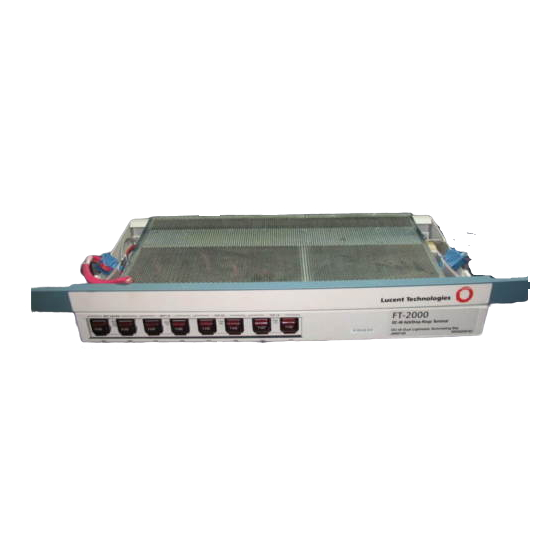
- Page 122 Platform Descriptions FT-2000 OC-48 Add/Drop-Rings Terminal (E-Bay) Equipment Packages The FT-2000 OC-48 Add/Drop-Rings Terminal is available in the following equipment package: FT-2000 OC-48 Add/Drop-Rings Terminal for two-Fiber Rings: The FT-2000 OC-48 Add/Drop-Rings Terminal for two-Fiber Rings (Figure 3-1) consists of the J68974E FT-2000 OC-48 Enhanced Lightwave Terminating Bay (or the J68974A FT-2000 OC-48 Lightwave Terminating Bay) and Releases 3.0.1-ADR...
- Page 123 Low Speed Shelf - 84" STS1E STS1E System Controller and/or and/or 4" PC Tray Filter Panel Interconnection Panel 21.5" Enhanced High Speed Shelf 4" Screen 4" Figure 3-1. FT-2000 OC-48 Add/Drop-Rings Terminal for Two-Fiber Rings (E-Bay) Issue 8.0 July 2002...
-
Page 124: Power Distribution And Fuse Panel
The power distribution and fuse panel (Figure 3-2) is located at the top of each FT-2000 OC-48 Lightwave System bay. It measures 2 inches high by 21.5 inches wide by 12 inches deep. The power distribution and fuse panel has a removable front cover that allows front access for shelf power connections. -
Page 125: Low-Speed Shelf - System Controller (Without Circuit Pack Cover)- Ed6G999-31, G5
Platform Descriptions The Low-Speed Shelf — System Controller (Figure 3-3) consists of a fully connectorized interconnection panel, a USER PANEL, and 25 circuit pack slots. It measures 21.5 inches high by 21.5 inches wide by 12 inches deep and fits in a standard 23-inch wide seismic network bay framework. -
Page 126: Low-Speed Shelf - System Controller (Without Circuit Pack Cover) - Ed6G999-32, G3
Platform Descriptions The Low-Speed Shelf — System Controller (Figure 3-4) is functionally identical to Figure 3-3 and is its new replacement. The main distinguishing differences are: (1) a slightly modified User Panel, and (2) a fully integrated backplane. User Panel Interconnection Panel and/or and/or... - Page 127 Platform Descriptions Low-Speed Shelf — System Controller Circuit Packs The Low-Speed Shelf — System Controller (Figure 3-3) provides the following circuit pack slots: LS INTFC 1A - 8B: Sixteen slots are provided for the following circuit packs. — LAA2/LAA2B DS3 Interface (DS3) (S1:1 or S4:4) circuit pack (service): The S1:1 DS3 circuit pack has been discontinued and replaced with the S4:4 DS3 circuit pack.
-
Page 128: Permitted Slot Locations For The Quad Circuit Pack
Platform Descriptions The OC-12 is a "quad-size" circuit pack and thus requires four adjacent low-speed slots as shown in Table 3-1. Table 3-1. Permitted Slot Locations for the Quad Circuit Pack OC-12 Quad Slot Locations Command Slot Extension Slots OC-12 Pack AID 1A-1B-2A-2B 1A, 2A, 2B ls-1b... - Page 129 Platform Descriptions Release 3.0.1-ADR software only. The LAA2/LAA2B DS3 (S4:4) circuit pack is compatible with Release 3.0.1-ADR or later software. The STS1E circuit pack is compatible with Release 4.0.0-ADR or later software. LSSW IN and OUT: Two slots are provided for the LAA12B Low Speed Switch (LSSW) circuit packs.
-
Page 130: Low-Speed Shelf - System Controller Circuit Pack Slot/Circuit Pack Code/Software Compatibility
Platform Descriptions Table 3-2 also provides circuit pack slot/circuit pack code/software compatibility information. Table 3-2. Low-Speed Shelf — System Controller Circuit Pack Slot/Circuit Pack Code/Software Compatibility Compatible Software (Note) Circuit Pack Supported Circuit R3.01 R4.0.0 R4.1.0 R5.0._ R6.0._ R701.0 R7.1.0 R7.2.0 Slot Pack Codes... - Page 131 "Operations Interfaces." For detailed information about terminal strip wiring, refer to 365-575-115, FT-2000 OC-48 Lightwave System, Releases 3, 4, 5, 6, and 7 Installation Manual and SD-5G250-02, FT-2000 OC-48 Enhanced Lightwave Terminating Bay Application Schematic (or SD-5G250-01, FT-2000 OC-48 Lightwave Terminating Bay Application Schematic ).
- Page 132 Platform Descriptions TIMING IN PRI and TIMING IN SECY: These connectors provide a primary (PRI) and secondary (SEC) interface to an external DS1 timing source that is required for synchronous operation. For more information about synchronization interfaces, refer to Volume I, Section 5, "Control, Transmission, and Synchronization Interfaces."...
-
Page 133: Interconnection Panel (Low-Speed Shelf - System Controller) -Ed6G999-32, G3
Platform Descriptions Except for power, all cabling entering the interconnection panel is connectorized with the following industry standard connectors: BNC connectors: The BNC connectors are used on all cables for electrical low-speed interfaces. D-subminiature connectors: The D-subminiature connectors are used on all cables for the operation system and central office interfaces. -
Page 134: User Panel (Enhanced) 6G999-31, G5
Platform Descriptions The user panel (Figure 3-7) provides −48 V power filters, a power on (PWR ON) LED, an electrostatic discharge jack, and system level information. For more information about the user panel, refer to Section 6, "Operations Interfaces." Critical Alarm Major Alarm Minor Alarm Alarm Cutoff/... -
Page 135: User Panel 6G999-32, G3
Platform Descriptions Functionally, the (newer) G3 User Panel is the same as the (older) G5 panel. However, there are minor physical differences. Figure 3-8 depicts the G3 user panel. Figure 3-8. User Panel 6G999-32, G3 3-15 Issue 8.0 July 2002... - Page 136 Platform Descriptions The Low-Speed Shelf — System Controller has two front covers (Figure 3-9). One cover covers the interconnection panel and the other covers the circuit packs. Openings are provided in the top cover that allow the user panel to show through and provide access to the (CIT) port.
- Page 137 † and 739S2 OC48 TRMTR (A/D) circuit packs are compatible with The High-Speed Shelf is used only on an FT-2000 OC-48 Add/Drop-Rings Terminal for two-Fiber Rings equipped with the J68974A FT-2000 OC-48 Lightwave Terminating Bay. † These transmitters and receivers are DA effective 06/30/97.
- Page 138 Platform Descriptions Release 6.0.0-ADR or later software. The 739B4, 739J4, 739B5, 739C5, 739J5, 739P5, 739R5, and 739S5 OC48 TRMTR (A/D) circuit packs are compatible with Release 7.0.0-ADR or later software. The 739E[1-16] circuit packs are compatible with Release 7.2.0 and later software. RCVR 1E: One slot is provided for the 839B2, 839B4B, 839B5, or 839E5 OC48 Receiver, Add/Drop (OC48 RCVR [A/D]) circuit pack for OC-48 high-speed line 1E.
-
Page 139: High-Speed Shelf Circuit Pack Slot/Circuit Pack Code/Software Compatibility
Platform Descriptions Table 3-3 also provides circuit pack slot/circuit pack code/software compatibility information. Table 3-3. High-Speed Shelf Circuit Pack Slot/Circuit Pack Code/Software Compatibility ADR Compatible Software (Note) Circuit Pack Supported Circuit Slot Pack Codes R3.0.1 R4.0.0 R4.1.0 R5.0._ R6.0._ R7.0.0 R7.1.0 R7.2.0 TRMTR 1W... - Page 140 Platform Descriptions Circuit pack keying prevents circuit packs from being accidentally inserted in incorrect slots. For detailed circuit pack descriptions and software compatibility information, refer to Section 7, "Circuit Pack Descriptions." High-Speed Shelf Interfaces Front access cabling is provided through the interconnection panel (Figure 3-11). -48A RTN -48A LINE...
- Page 141 Platform Descriptions SECTION OW (LOC OW) LINE (X) and LINE (Y): These connectors provide an interface that allows an orderwire (OW) set access to the section orderwire (E1 byte) for voice communications. For more information about the orderwire interface, refer to Section 6, "Operations Interfaces."...
- Page 142 Platform Descriptions The filter panel (Figure 3-12) provides −48 V power filters, a power on (PWR ON) LED, and an electrostatic discharge jack for the High-Speed Shelf. For more information about the filter panel, refer to Section 6, "Operations Interfaces." -48 V Power On LINE Line...
- Page 143 Platform Descriptions The High-Speed Shelf has two front covers (Figure 3-13). One cover covers the interconnection panel and the other covers the circuit packs. Openings are provided in the top cover that allow the filter panel to show through. The covers are hinged and can be easily removed for maintenance access.
- Page 144 Release 7.0.0-ADR or later software. The 739E[1-16] circuit packs are compatible with Release 7.2.0 and later software. The Enhanced High-Speed Shelf is used only on FT-2000 OC-48 Add/Drop-Rings Terminal for two-Fiber Rings equipped with the J68974E FT-2000 OC-48 Enhanced Lightwave Terminating Bay.
- Page 145 Platform Descriptions RCVR 1W: One slot is provided for the 839B2, 839B4B, 839B5, or 839E5 OC48 Receiver, Add/Drop (OC48 RCVR [A/D]) circuit packs for OC-48 high-speed line 1E. The 839B4B and 839B5 OC48 RCVR (A/D) circuit packs are compatible with Release 7.0.0-ADR or later software. The 839E5 circuit pack is compatible with Release 7.2.0 and later software.
- Page 146 Platform Descriptions Filter Panel Interconnection Panel Cover TRMTR RCVR TRMTR RCVR TRMTR RCVR TRMTR RCVR LNCTL OHCTL OHCTL LOHCTL LOHCTL Figure 3-14. Enhanced High-Speed Shelf (Without Circuit Pack Cover) 3-26 Issue 8.0 July 2002...
-
Page 147: Enhanced High-Speed Shelf Circuit Pack Slot/Circuit Pack Code/Software Compatibility
Platform Descriptions Table 3-4 also provides circuit pack slot/circuit pack code/software compatibility information. Table 3-4. Enhanced High-Speed Shelf Circuit Pack Slot/Circuit Pack Code/Software Compatibility ADR Compatible Software (Note) Circuit Pack Supported Circuit Pack Slot Codes R3.0.1 R4.0.0 R4.1.0 R5.0._ R6.0._ R7.0.0 R7.1.0 R7.2.0... - Page 148 Platform Descriptions Circuit pack keying prevents circuit packs from being accidentally inserted in incorrect slots. For detailed circuit pack descriptions and software compatibility information, refer to Section 7, "Circuit Pack Descriptions." Enhanced High-Speed Shelf Interfaces Front access cabling is provided through the interconnection panel (Figure 3-15). J251A J271A J252A...
- Page 149 Platform Descriptions The interconnection panel provides the following interfaces: LINE GROWTH CHAN LINE (X) and LINE (Y): These connectors provide an interface that allows access to the line growth channel (Z1 and Z2 bytes) of the OC-48 high-speed lines. These connectors are reserved for use in a future release.
- Page 150 Platform Descriptions Enhanced High Speed Shelf Figure 3-16. Enhanced High-Speed Shelf (with Covers) 3-30 Issue 8.0 July 2002...
- Page 151 Platform Descriptions Heat Baffle The heat baffles prevent heat rising from the shelf below from entering the shelf above. A front cover is provided to maintain a flush appearance. PC Tray The PC tray is a combination PC tray and heat baffle. It provides a place to hold a portable PC (for example, the NCR* 3170 computer) weighing up to 25 pounds and measuring up to 20 inches wide and 12 inches deep.
- Page 152 Platform Descriptions FT-2000 OC-48 Repeater (R-Bay) Equipment Packages The FT-2000 OC-48 Repeater Bay is available in the following equipment packages: FT-2000 OC-48 Repeater Bay: The FT-2000 OC-48 Repeater Bay (Figure 3-17) consists of the J68974R FT-2000 OC-48 Repeater Bay and Release 2.1.0-RPTR*, Release 4.0.0-RPTR, or Release 6.0.0-RPTR...
- Page 153 Heat Baffle 4" User Panel 21.5" 84" Repeater Shelf - System Controller 4" PC Tray User Panel 21.5" Repeater Shelf - System Controller 4" Screen 4" 21.5" tpa 814210/01 Figure 3-17. FT-2000 OC-48 Repeater Bay 3-33 Issue 8.0 July 2002...
- Page 154 Platform Descriptions User Panel Interconnection Panel Cover PC Tray Figure 3-18. FT-2000 OC-48 Repeater Shelf (Miscellaneously Mounted) 3-34 Issue 8.0 July 2002...
-
Page 155: Power Distribution And Fuse Panel
The power distribution and fuse panel (Figure 3-19) is located at the top of each FT-2000 OC-48 Lightwave System bay. It measures 2 inches high by 21.5 inches wide by 12 inches deep. The power distribution and fuse panel has a removable front cover that allows front access for shelf power connections. -
Page 156: Circuit Pack Cover)
Platform Descriptions Repeater Shelf — System Controller Purpose of Repeater Shelf — System Controller The Repeater Shelf — System Controller provides high-level system control functions and regenerates OC-48 signals for two OC-48 high-speed lines. The Repeater Shelf — SYSCTL (Figure 3-20) consists of the fully connectorized interconnection panel, a user panel, and eight circuit pack slots. - Page 157 Platform Descriptions Repeater Shelf — System Controller Circuit Packs The Repeater Shelf — System Controller (Figure 3-20) provides the following circuit pack slots: REGENR 1EW and 1WE: Two slots are provided for the 39B1, 39C1, 39B2, 39C2, 39J2, 39R2, or 39S2 OC48 Regenerator (OC48 REGENR) circuit packs for one OC-48 high-speed line.
-
Page 158: Repeater Shelf - System Controller Circuit Pack Slot/Circuit Pack Code/Software Compatibility
Platform Descriptions Table 3-5 also provides circuit pack slot/circuit pack code/software compatibility information. Table 3-5. Repeater Shelf — System Controller Circuit Pack Slot/Circuit Pack Code/Software Compatibility Supported Circuit Compatible Software (Note) Circuit Pack Slot Pack Codes R2.1.0-RPTR R4.0.0-RPTR R6.0.0-RPTR REGENR 1EW and 39B1 OC48 REGENR* 39B2 OC48 REGENR 39C1 OC48 REGENR* X... - Page 159 SHELF CONTROL: These connectors are reserved for use in a future release. (These connectors and the associated cabling are not provided on the miscellaneously mounted FT-2000 OC-48 Repeater Shelf.) OFFICE ALMS: This connector provides an interface to the local office audible and visible alarms.
- Page 160 CONTROL BUS OUT and IN: These connectors are reserved for use in a future release. (These connectors and the associated cabling are not provided on the miscellaneously mounted FT-2000 OC-48 Repeater Shelf.) SECTION USER CHAN LINE 1 and LINE P: These connectors are reserved for use in a future release.
-
Page 161: User Panel (Ft-2000 Oc-48 Repeater Shelf) For Miscellaneous Mounting Only
Figure 3-22 shows the user panel for the miscellaneously mounted FT-2000 OC-48 Repeater Shelf. Figure 3-7 shows the user panel for the FT-2000 OC-48 Repeater Bay except the line identification label is the same as shown in Figure 3-22. For more information about the user panel, refer to Volume I, Section 6, "Operations Interfaces."... -
Page 162: Repeater Shelf - System Controller With Covers
CIT port. The covers are hinged and can be easily removed for maintenance access. Figure 3-23 shows the Repeater Shelf — System Controller with covers for the FT-2000 OC-48 Repeater Bay. Figure 3-24 shows the Repeater Shelf — System Controller with covers for the miscellaneously mounted FT-2000 OC-48 Repeater Shelf. -
Page 163: Repeater Shelf - System Controller With Covers (Ft-2000 Oc-48 Repeater Shelf)
Platform Descriptions FT-2000 OC-48 Repeater Shelf Figure 3-24. Repeater Shelf — System Controller with Covers (FT-2000 OC-48 Repeater Shelf) 3-43 Issue 8.0 July 2002... - Page 164 The screen provides a filter panel at the bottom of the bay and an air intake plenum for cooling purposes. Upgrades The FT-2000 OC-48 Repeater Bay equipped with one Repeater Shelf — System Controller can be upgraded in service with up to two additional Repeater Shelf — System Controllers.
- Page 165 Platform Descriptions FT-2000 OC-48 Dual ADR Terminal (D-Bay) Equipment Packages This equipment package is identified as J68974D. Conceptually, the D-Bay is very similar to the E-Bay. The main differences are: A modified power distribution and fuse panel A more compact arrangement of the circuit pack shelves A new high-speed shelf—which is identified as the "Condensed...
- Page 166 High Speed Shelf Line 1W Line 1E Line 1W Line 1E J254A J274A J256A J276A Intraoffice J10A J277A 5" Screen and Fan Shelf 4" Figure 3-25. FT-2000 OC-48 Dual ADR Terminal for Two-Fiber Rings (D-Bay) 3-46 Issue 8.0 July 2002...
-
Page 167: Fuse Panel
The power distribution and fuse panel (Figure 3-26) is located at the top of each FT-2000 OC-48 D-Bay. It measures 2 inches high by 21.5 inches wide by 12 inches deep. The power distribution and fuse panel has a removable front cover that allows for shelf power connections. -
Page 168: Low-Speed Shelf - System Controller (Without Circuit Pack Cover) - Ed6G999-31, G5
Platform Descriptions The Low-Speed Shelf — System Controller (Figure 3-27) consists of a fully connectorized interconnection panel, a user panel, and 25 circuit pack slots. It measures 21.5 inches high by 21.5 inches wide by 12 inches deep and fits in a standard 23-inch wide seismic network bay framework. -
Page 169: Low-Speed Shelf - System Controller (Without Circuit Pack Cover) - Ed6G999-32, G3
Platform Descriptions The Low-Speed Shelf — System Controller (Figure 3-28) is functionally identical to Figure 3-27 and is its new replacement. The main distinguishing differences are: (1) a slightly modified User Panel and (2) a fully integrated backplane. User Panel Interconnection Panel and/or and/or... -
Page 170: Permitted Slot Locations For The Quad Circuit Pack
Platform Descriptions Low-Speed Shelf — System Controller Circuit Packs The Low-Speed Shelf — System Controller (Figure 3-28) provides the following circuit pack slots: — LS INTFC 1A - 8B: Sixteen slots are provided for the following circuit packs. — LAA2/LAA2B DS3 Interface (DS3) (S4:4) circuit pack (service): —... - Page 171 Platform Descriptions NOTE: Each quad location consists of one command slot and three extension slots. The command slot address is used in the OC-12 provisioning commands and for reporting any circuit pack and OC-12 signal-related alarm conditions. The extension slots are used to gain access to the STS-3 signals, in conjunction with cross-connect commands, and for reporting tributary related alarms.
-
Page 172: Low-Speed Shelf - System Controller Circuit Pack Slot/Circuit Pack Code/Software Compatibility
Platform Descriptions — SYSCTL: One slot is provided for the LAA23B System Controller (SYSCTL) circuit pack. — SYSMEM: One slot is provided for the LAA25 System Memory (SYSMEM) circuit pack. Table 3-7 also provides circuit pack slot/circuit pack code/software compatibility information. - Page 173 "Operations Interfaces." For detailed information about terminal strip wiring, refer to 365-575-115, FT-2000 OC-48 Lightwave System, Releases 3, 4, 5, 6, and 7 Installation Manual , and SD-5G250-02, FT-2000 OC-48 Enhanced Lightwave Terminating Bay Application Schematic (or SD-5G250-01, FT-2000 OC-48 Lightwave Terminating Bay Application Schematic ).
-
Page 174: Interconnection Panel (Low-Speed Shelf - System Controller)-Ed6G999-31,G5
Platform Descriptions TIMING OUT 1 and TIMING OUT 2: These connectors provide an interface to other central office equipment that requires a DS1 timing reference signal. For more information about synchronization interfaces, refer to Volume I, Section 5, "Control, Transmission, and Synchronization Interfaces."... - Page 175 Platform Descriptions Except for power, all cabling entering the interconnection panel is connectorized with the following industry standard connectors: BNC connectors: The BNC connectors are used on all cables for electrical low-speed interfaces. D-subminiature connectors: The D-subminiature connectors are used on all cables for the operation system and central office interfaces.
-
Page 176: Low-Speed Shelf - System Controller (With Covers)
Platform Descriptions The Low-Speed Shelf - System Controller has two front covers (Figure 3-31). One covers the interconnection panel and the other covers the circuit packs. Openings are provided in the top cover that allow the user panel to show through and provide access to the CIT port. -
Page 177: Condensed High-Speed Shelf
TRMTR (A/D) circuit packs are compatible with Release 7.0.0-ADR or later software. The 739E[1-16] circuit packs are compatible with Release 7.2.0 and later software. The Condensed High-Speed Shelf is used only on FT-2000 OC-48 Add/Drop-Rings Terminal for two-Fiber Rings equipped with the J68974D FT-2000 OC-48 Enhanced Lightwave Terminating Bay. - Page 178 Platform Descriptions † RCVR 1E: One slot is provided for the 839B2 , 839B4B, or 839B5 OC48 Receiver, Add/Drop (OC48 RCVR [A/D]) circuit packs for OC-48 high- speed line 1E. The 839B4B and 839B5 OC48 RCVR (A/D) circuit Packs are compatible with Release 7.0.0-ADR or later software. The 839E5 circuit pack is compatible with Release 7.2.0 and later software.
-
Page 179: Pack Cover)
Platform Descriptions TRMTR RCVR TRMTR RCVR (1W) (1W) (1E) (1E) (1W)(1E) Figure 3-32. Condensed High-Speed Shelf (Without Circuit Pack Cover) 3-59 Issue 8.0 July 2002... -
Page 180: Enhanced High-Speed Shelf Circuit Pack Slot/Circuit Pack Code/Software Compatibility
Platform Descriptions Table 3-8 also provides circuit pack slot/circuit pack code/software compatibility information. Table 3-8. Enhanced High-Speed Shelf Circuit Pack Slot/Circuit Pack Code/Software Compatibility ADR Compatible Software Circuit Pack Slot Supported Circuit Pack Codes R7.0.0 R7.1.0 R7.2.0 † TRMTR 1W 739B2 OC48 TRMTR †... - Page 181 Platform Descriptions Table 3-8. Enhanced High-Speed Shelf Circuit Pack Slot/Circuit Pack Code/Software Compatibility (Cont’d) ADR Compatible Software Circuit Pack Supported Circuit Pack Slot Codes R7.0.0 R7.1.0 R7.2.0 RCVR 1E 839B2 OC48 RCVR 839B4B OC48 RCVR 839B5 OC48 RCVR 839E5 OC48 RCVR LNCTL LAA28 LNCTL OHCTL 1W...
-
Page 182: Interconnection And Filter Panel
Platform Descriptions Condensed High-Speed Shelf Interfaces Front access cabling (for ordering and power) is provided through the Interconnection and Filter Panel (Figure 3-33). Line 1W Line 1E Line 1W Line 1E J256A J276A J254A J274A Line 1W Line 1E Line 1W Line 1E J252A J272A... - Page 183 Platform Descriptions The interconnection and filter panel is divided into six segments. They are labeled A-through-F and each interface is described as follows: A - SECTION OW (LOC OW) LINE (1W) and LINE (1E): These connectors provide an interface that allows an orderwire set access to the section orderwire (E1 byte) for voice communications (local orderwire).
- Page 184 Platform Descriptions The fan assembly contains two status LEDs. These are: Power-On Alarm. The alarm signal is brought from a connector located on the left side of the fan assembly and terminated on the "miscellaneous discrete alarm inputs connector" which is located on the lower low-speed shelf. 3-64 Issue 8.0 July 2002...
- Page 185 Power Table of Contents Overview General Power Distribution Power Dissipation LEDs Issue 8.0 July 2002...
- Page 186 Table of Contents 4-ii Issue 8.0 July 2002...
- Page 187 "hot spots." The FT-2000 OC-48 Lightwave System is powered by −48 V DC. The voltage range for all the components is −42.75 to −60 V DC as measured at the power feeder inputs and returns at the bay.
-
Page 188: Bay Power Distribution
The FT-2000 OC-48 Lightwave System accepts two −48 V DC office power feeders for feeder redundancy from the battery distribution and fuse bay (BDFB) or equivalent. Figure 4-1 shows how power is distributed in an FT-2000 OC-48 Lightwave System bay. The power feeders are 4.5-foot, 8-gauge power feeder stubs gutter-tapped to the feeder cables going to the BDFB. -
Page 189: Miscellaneously-Mounted
(if equipped). Figure 4-2 shows an example of how power is distributed to a miscellaneously mounted FT-2000 OC-48 Repeater Shelf. The 8-gauge power feeder stubs are terminated at two 10-gauge power connectors that are connected to the user panel. The user panel is equipped with two 10-amp fuses: one fuse for power feeder A and one fuse for power feeder B (red lamp is lighted when blown). -
Page 190: Shelf Power Distribution
Power The two independent −48 volt office power feeders (A and B) enter each shelf via a power interface circuit and are distributed to the circuit packs (Figure 4-3) via the printed backplane. The power interface circuit consists of a green PWR ON LED, two power filter assemblies, and two radio-frequency (RF) filters. - Page 191 Power Each circuit pack is equipped with diodes and fuses that protect the power feeders (Figure 4-4). A filtering section follows the fused input. Modular DC-to-DC power converters on each circuit pack convert the −48 V to the voltages required on the circuit pack.
-
Page 192: Rings (D-Bay)
Table 4-1 shows the maximum power dissipation and current drains for the FT-2000 OC-48 Lightwave System. NOTE: Refer to the Floor Plan Data Sheet (FPD 804-911-168-[ ]) for complete information on power engineering for the FT-2000 OC-48 Lightwave System. Table 4-1. Power Dissipation and Current Drains... - Page 193 The red FAULT LED shows circuit pack failures. If the fuse or DC-to-DC converter fails on a transmission circuit pack at an FT-2000 OC-48 Repeater Bay, the red FAULT LED will be operated via a separate power path from the System Controller (SYSCTL) circuit pack.
- Page 194 Power Issue 8.0 July 2002...
- Page 195 Control, Transmission, and Synchronization Interfaces Table of Contents Overview Control Transmission FT-2000 OC-48 Add/Drop-Rings Terminal FT-2000 OC-48 Repeater Bay Synchronization Modes 5-10 Platform Synchronization 5-10 General 5-10 Free Running Mode 5-11 Line Timed Mode 5-12 Through Timed Mode 5-13 Loop Timed Mode—only for Point-to-Point Releases of FT-2000 5-15...
- Page 196 Table of Contents Ring Applications Not Used to Distribute Timing 5-28 Synchronous Applications (With a Mixture of Asynchronous and Synchronous Low-Speed Interfaces) 5-30 Ring Applications Used to Distribute Timing 5-35 Summary of Timing Rules for Bidirectional Line-Switched Rings 5-43 5-ii Issue 8.0 July 2002...
- Page 197 Figure 5-1 shows the system control architecture for the FT-2000 OC-48 Add/Drop-Rings Terminal. Figure 5-2 shows the system control architecture for the FT-2000 OC-48 Repeater Bay. The system control architecture distributes the monitoring and control functions down to the lowest level where a particular function (for example, switching or timing) is performed.
-
Page 198: Controller
Control, Transmission, and Synchronization Interfaces User Panel LEDs Office Alarms Alarm Cutoff SYSMEM Parallel Telemetry User-Settable Discrete Input User-Settable Discrete Output System Controller Complex CIT DCE CIT DTE SYSCTL Serial Telemetry X.25 LCLAN OALAN LNCTL BCLAN OHCTL Board (TERM) Controller OHCTL (TERM) Board... -
Page 199: System Control Architecture For The
The LNCTL circuit pack is responsible for fault recovery. The LNCTL circuit pack communicates with the board controllers to activate protection switching. The middle level of the control hierarchy is not needed in the FT-2000 OC-48 Repeater Bay. Therefore, the FT-2000 OC-48 Repeater Bay does not require any LNCTL circuit packs. - Page 200 (OC-3/OC-12) section DCC information (bytes D1-D3). In Release 6 and later releases, the Orderwire (OW) circuit pack performs SONET section overhead access functions at FT-2000 OC-48 Repeater Bays. The OW circuit pack provides access to the OC-48 section orderwire (E1) and user channel (F1) bytes.
-
Page 201: Oc-48 Add/Drop-Rings Terminal For 2-Fiber Rings Transmission Block Diagram
Transmission FT-2000 OC-48 Add/Drop-Rings Terminal The FT-2000 OC-48 Add/Drop-Rings Terminal for 2-Fiber Rings allows groups of three DS3 signals, three EC-1 signals (available in Release 4 and later releases), one OC-3 signal (available in Release 5 and later releases), and/or GNE OC-12 (available in Release 7 and later) to be easily added/dropped while the through traffic is passed on without requiring low speed interface circuit packs. - Page 202 Control, Transmission, and Synchronization Interfaces The FT-2000 OC-48 Add/Drop-Rings Terminal for 2-Fiber Rings interfaces with up to 48 bidirectional DS3 equivalent signals (DS3, EC-1, and/or OC-3 ) and 2 OC-48 high speed lines (1E and 1W). Each OC-48 high speed line consists of sixteen 155 Mb/s (STS-3) tributaries.
- Page 203 Control, Transmission, and Synchronization Interfaces CAUTION: All DS3 and EC-1 signal outputs from the FT-2000 OC-48 Add/Drop-Rings Terminal for 2-Fiber Rings must be properly terminated at all times. Therefore, these outputs must be connected to cross-connect panels that have internal 75-ohm terminations (for example, Lucent Technologies...
- Page 204 Volume I, Section 7, "Circuit Pack Descriptions." In Release 5 and later releases, the FT-2000 OC-48 Add/Drop-Rings Terminal for 2-Fiber Rings also provides limited support for STS-1 cross-connections across an STS-3 tributary.
-
Page 205: Ft-2000 Oc-48 Repeater Bay Transmission
Control, Transmission, and Synchronization Interfaces FT-2000 OC-48 Repeater Bay The FT-2000 OC-48 Repeater Bay regenerates optical OC-48 signals for up to six OC-48 high speed lines. Figure 5-4 shows a transmission block diagram of the FT-2000 OC-48 Repeater Bay for one 1x1 system. - Page 206 Control, Transmission, and Synchronization Interfaces Synchronization Modes Platform Synchronization General The FT-2000 OC-48 Lightwave System platforms can be provisioned for the following synchronization modes: FT-2000 OC-48 Add/Drop-Rings Terminal — Free running from an internal oscillator — Through timed from an incoming OC-48 signal —...
-
Page 207: System Controller
Two TG3 (DS1) circuit packs are located on each Low Speed Shelf and support the synchronization needs of the FT-2000 OC-48 Lightwave System. The FT-2000 OC-48 Repeater Bay does not require TG3 (DS1) circuit packs. The TG3 (DS1) circuit packs are 1x1 (revertive) protected, protecting against circuit pack failures. - Page 208 Control, Transmission, and Synchronization Interfaces Line Timed Mode The line timed mode of synchronization is available in FT-2000 OC-48 ADR Release 7.2 and later releases. It provides several benefits which make it superior to other modes—particularly with FT-2000 nodes that are located in sites without BITS clocks.
-
Page 209: Through Timed Synchronization
Control, Transmission, and Synchronization Interfaces Through Timed Mode In the through timed mode, an intermediate site (FT-2000 OC-48 Add/Drop-Rings Terminal or FT-2000 OC-48 Repeater Bay) derives timing from the incoming OC-48 signals. In the FT-2000 OC-48 Add/Drop-Rings Terminal, the TG3 (DS1) circuit packs derive timing from the incoming OC-48 signals (Figure 5-6). -
Page 210: Through Timed Synchronization
REGENR circuit pack that accepts the incoming OC-48 signal from high speed line 1W derives timing for the OC-48 signal transmitted on high speed line 1E. The FT-2000 OC-48 Repeater Bay does not require TG3 (DS1) circuit packs. OC-48 OC-48... -
Page 211: Loop Timed Synchronization
Control, Transmission, and Synchronization Interfaces Loop Timed Mode—only for Point-to-Point Releases of FT-2000 In the loop timed mode (Figure 5-8), the TG3 (DS1) circuit packs on the Low Speed Shelf - System Controller derive timing from the incoming OC-48 signals. The TG3 (DS1) circuit packs accept an OC-48 line reference signal (25.92 MHz) from the OC48 RCVR circuit packs and derive the internal synchronization used by the transmission packs. - Page 212 Control, Transmission, and Synchronization Interfaces accommodated. In the holdover mode, the on-board oscillator frequency will not degrade below the stratum 3 level. The TG3 (DS1) circuit packs distribute 155.52 MHz timing signals to the low speed interface circuit packs on the Low Speed Shelf - System Controller and the OC48 TRMTR circuit packs on the Enhanced High Speed Shelf (or High Speed Shelf).
-
Page 213: Externally Timed Synchronization
(Figure 5-9), each TG3 (DS1) circuit pack accepts a DS1 synchronization reference signal from an external stratum 3 or better clock. In bidirectional 2-fiber ring applications, the DS1 references synchronize the local FT-2000 OC-48 Add/Drop-Rings Terminal, and other FT-2000 OC-48 Add/Drop-Rings Terminals that are through timed, with other network equipment operating under the same primary clock source. - Page 214 Control, Transmission, and Synchronization Interfaces In the externally timed mode, the LAA18 TG3 (DS1) circuit packs can also provide DS1 synchronization output signals to the office BITS clock or other central office equipment. The DS1 reference input interface (TIMING IN PRI and TIMING IN SECY) and the DS1 reference output interface (TIMING OUT 1 and TIMING OUT 2) are located on the interconnection panel of the Low Speed Shelf - System Controller.
- Page 215 The synchronization features of the FT-2000 OC-48 Lightwave System are designed to complement existing and future network synchronization and, hence, allow it not only to make use of network synchronization but also to take an active role in facilitating network synchronization.
- Page 216 Control, Transmission, and Synchronization Interfaces OC-48 point-to-point applications with asynchronous (DS3) low speed interfaces — Free running/free running configuration — Free running/through timed configuration — Phase locked/phase locked configuration Bidirectional ring applications with asynchronous (DS3) and synchronous (EC-1, OC-3 and/or OC-12) low speed interfaces —...
-
Page 217: Free Running/Free Running Configuration
The free running/free running configuration applies to OC-48 point-to-point applications (with or without FT-2000 OC-48 Repeater Bays) with asynchronous (DS3) low speed interfaces only. In the free running/free running configuration (Figure 5-10), both terminals are free running;... -
Page 218: Free Running/Through Timed Configuration
(with or without FT-2000 OC-48 Repeater Bays) with asynchronous (DS3) low speed interfaces only. In the free running/through timed configuration (Figure 5-11), one FT-2000 OC-48 Add/Drop-Rings Terminal times its transmitted signals from its free running internal oscillator. The internal oscillator at the other FT-2000 OC-48 Add/Drop-Rings Terminal uses the OC-48 line reference signal recovered from the incoming OC-48 signal to derive timing for its transmitted signals. -
Page 219: Externally Timed/Through Timed Configuration
The externally timed/through timed configuration applies to all OC-48 point-to-point applications (with or without the FT-2000 OC-48 Repeater Bay). The FT-2000 OC-48 Add/Drop-Rings Terminal in the through timed mode may be equipped with two DS1 external synchronization references. If the OC-48 line reference signals fail, the TG3 (DS1) circuit pack holds the on-board oscillator frequency at the last good reference sample (holdover mode). -
Page 220: Phase Locked/Phase Locked Configuration
Control, Transmission, and Synchronization Interfaces Phase Locked/Phase Locked Configuration In the phase locked/phase locked configuration, both FT-2000 OC-48 Point-to-Point or Add/Drop-Rings Terminals time their transmitted signals from internal oscillators that are locked to the DS1 external synchronization reference. Since this configuration requires local office clocks at each end terminal, it is most suited to interoffice applications. -
Page 221: Phase Locked/Phase Locked Configuration [Laa18 Tg3 (Ds1) Circuit Pack]
Control, Transmission, and Synchronization Interfaces An FT-2000 OC-48 Add/Drop-Rings Terminal equipped with the LAA18 TG3 (DS1) circuit pack can also provide DS1 synchronization outputs to the office BITS clock or other central office equipment (Figure 5-14). For more information about platform timing modes, refer to "Platform Synchronization"... -
Page 222: Externally Timed/Externally Timed Configuration
1 clock. The externally timed/externally timed configuration applies to all OC-48 Add/Drop-Rings Terminal applications (with or without the FT-2000 OC-48 Repeater Bay). The LAA18 TG3 (DS1) circuit pack can also provide DS1 synchronization outputs to the office BITS clock or other central office equipment. - Page 223 T1 facilities that users may not wish to convert. Therefore, the FT-2000 OC-48 Lightwave System may or may not be used for distributing timing signals. The user must decide if the FT-2000 ring will be used to distribute timing signals to BITS clocks.
-
Page 224: Example Of A Ring Application With One Node Provisioned Free Running And All Other Nodes Provisioned Through Timed (Without Timing Drops)
Control, Transmission, and Synchronization Interfaces Ring Applications Not Used to Distribute Timing Asynchronous Applications (DS-3 Low Speed Interfaces Only) . In ring applications not used to distribute timing signals to BITS clocks, there are six possible synchronization configurations. The two asynchronous configurations are as follows: One node provisioned free running;... -
Page 225: Example Of A Ring Application With One Node Provisioned Free Running And All Other Nodes Provisioned Line Timed (Without Timing Drops)
Control, Transmission, and Synchronization Interfaces One node provisioned free running; all other nodes provisioned Line Timed: Refer to (Figure 5-17). FT-2000 Free Running FT-2000 FT-2000 Line Timed FT-2000 Figure 5-17. Example of a Ring Application with One Node Provisioned Free Running and All Other Nodes Provisioned Line Timed (Without Timing Drops) NOTE: If synchronous (EC-1, OC-3, IS-3 and/or OC-12) low speed... - Page 226 Control, Transmission, and Synchronization Interfaces Synchronous Applications (With a Mixture of Asynchronous and Synchronous Low-Speed Interfaces) One node provisioned externally timed; all other nodes provisioned through timed, line timed, or externally timed: This configuration (Figure 5-18, Figure 5-19, Figure 5-20, and Figure 5-21) are used with asynchronous (DS3) or synchronous (EC-1, OC-3 and/or OC-12) low speed interfaces, or a mix of synchronous and asynchronous low speed interfaces.
-
Page 227: Example Of A Ring Application With One Node Provisioned Externally Timed And All Other Nodes Provisioned Through Timed (Without Timing Drops)
Control, Transmission, and Synchronization Interfaces BITS Externally Timed FT-2000 DS3/EC-1/OC-3 FT-2000 FT-2000 DS3/EC-1/OC-3 DS3/EC-1/OC-3 Through Timed P = TIMING IN PRI to TG3-1 S = TIMING IN SECY to TG3-2 FT-2000 DS3/EC-1/OC-3 Figure 5-18. Example of a Ring Application with One Node Provisioned Externally Timed and All Other Nodes Provisioned Through Timed (Without Timing Drops) 5-31... -
Page 228: Provisioned Line Timed (Without Timing Drops)
Control, Transmission, and Synchronization Interfaces BITS P = TIMING IN PRI to TG3-1 S = TIMING IN SECY to TG3-2 FT-2000 Node A Externally Timed FT-2000 FT-2000 Node B DS3/EC-1/OC-3 DS3/EC-1/OC-3 IS-3/OC-12 IS-3/OC-12 Node D Line Timed Node C FT-2000 DS3/EC-1/OC-3 Provisioning Modes: IS-3.OC-12... -
Page 229: Example Of A Ring Application With Two Nodes
Control, Transmission, and Synchronization Interfaces BITS Externally Timed FT-2000 DS3/EC-1/OC-3 FT-2000 FT-2000 DS3/EC-1/OC-3 DS3/EC-1/OC-3 DS3/EC-1/OC-3 P = TIMING IN PRI to TG3-1 FT-2000 S = TIMING IN SECY to TG3-2 Externally Timed BITS Figure 5-20. Example of a Ring Application with Two Nodes Provisioned Externally Timed and All Other Nodes Provisioned Through Timed or Externally Timed (Without Timing Drops) -
Page 230: Example Of A Ring Application With Three Nodes Provisioned Externally Timed And One Node Provisioned Line Timed (Without Timing Drops)
Control, Transmission, and Synchronization Interfaces BITS P = TIMING IN PRI to TG3-1 S = TIMING IN SECY to TG3-2 Node A FT-2000 Externally Timed Node B Node D FT-2000 FT-2000 Line Timed Provisioning Modes: Node C Node A: External, E Back-up; Node B: External, W Back-up;... -
Page 231: Example Of A Ring Application With One Node Provisioned Externally Timed And All Other Nodes Provisioned Line Timed (With Two Timing Drops)
Control, Transmission, and Synchronization Interfaces Ring Applications Used to Distribute Timing For ring applications (FT-2000 Release 7.2.0 and later software) that are used to distribute timing, it is recommended that "Line Timed" mode of synchronization be used. Through timing is also (still) acceptable. In ring applications used to distribute timing signals to BITS clocks, there are two possible configurations. -
Page 232: Example Of A Ring Application With One Node Provisioned Externally Timed And All Other Nodes Provisioned Through Timed (With Timing Drops)
Control, Transmission, and Synchronization Interfaces One node provisioned externally timed; all other nodes provisioned through timed or externally timed: In this configuration (Figure 5-23 and Figure 5-24), at least one node should be provisioned externally timed (phase locked in releases prior to Release 5), and any nodes that drop timing signals should be provisioned through timed. -
Page 233: Example Of A Ring Application With One Node Provisioned Externally Timed And All Other Nodes Provisioned Through Timed Or Externally Timed (With Timing Drops)
Control, Transmission, and Synchronization Interfaces Independent BITS Clock Externally Timed FT-2000 DS3/EC-1/OC-3 FT-2000 FT-2000 BITS DS3/EC-1/OC-3 DS3/EC-1/OC-3 BITS DS3/EC-1/OC-3 P = TIMING IN PRI to TG3-1 S = TIMING IN SECY to TG3-2 FT-2000 1 = TIMING OUT 1 from TG3-1 2 = TIMING OUT 2 from TG3-2 Externally Timed Independent... - Page 234 Control, Transmission, and Synchronization Interfaces For the nodes that distribute the timing signal, the LAA18 TG3 (DS1) circuit pack should be used. The LAA18 TG3 (DS1) circuit pack provides a timing signal (DS1 synchronization output) derived directly from the OC-48 high speed line.
-
Page 235: Example Of A Ring Application With All Nodes Provisioned Externally Timed (With Timing Drops)
Control, Transmission, and Synchronization Interfaces All nodes provisioned externally timed: This configuration (Figure 5-25) is for users with BITS or stratum 1 traceable clocks at all nodes in the ring. At least one node must be externally timed with a stratum 1 traceable source that is not derived from the ring. -
Page 236: Example Of A Timing Loop Resulting From Incorrect Provisioning
Control, Transmission, and Synchronization Interfaces Independent BITS Clock Externally Timed FT-2000 DS3/EC-1/OC-3 FT-2000 FT-2000 BITS BITS DS3/EC-1/OC-3 Externally Externally Timed Timed DS3/EC-1/OC-3 Fiber Cut P = TIMING IN PRI to TG3-1 S = TIMING IN SECY to TG3-2 FT-2000 1 = TIMING OUT 1 from TG3-1 2 = TIMING OUT 2 from TG3-2 Through Timed Figure 5-26. -
Page 237: Example Of A Timing Loop Resulting From Inconsistent Ds1
Control, Transmission, and Synchronization Interfaces Independent BITS Clock Externally Timed FT-2000 DS3/EC-1/OC-3 FT-2000 FT-2000 BITS BITS DS3/EC-1/OC-3 Externally Externally Timed Timed DS3/EC-1/OC-3 P = TIMING IN PRI to TG3-1 S = TIMING IN SECY to TG3-2 FT-2000 1 = TIMING OUT 1 from TG3-1 Externally Timed 2 = TIMING OUT 2 from TG3-2 BITS... -
Page 238: Example Of A Ring Application With All Nodes Provisioned Externally Timed (With External Timing Emulation Cable)
Control, Transmission, and Synchronization Interfaces If a BITS or stratum 1 traceable clock is not available at a node and externally timed provisioning is desired, an external timing emulation (null BITS) cable may be used to emulate BITS operation (Figure 5-28). The external timing emulation cable connects TIMING OUT 1 to TIMING IN PRI, or TIMING OUT 2 to TIMING IN SECY at the node. - Page 239 Control, Transmission, and Synchronization Interfaces Summary of Timing Rules for Bidirectional Line-Switched Rings Strategy 1 Strategy 1 is applicable for all ring topologies. At least one node must be externally timed from a stratum 1 traceable timing source that is not distributed by this ring. Nodes used as a timing drop must be through timed.
- Page 240 Control, Transmission, and Synchronization Interfaces 5-44 Issue 8.0 July 2002...
-
Page 241: Filter Panel
Operations Interfaces Table of Contents Overview Craft Interface Terminal General PC with FT-2000 CIT-PC Software PC with CPro-2000 Software ASCII-Based Terminal Local Access Through the CIT (DCE) Port Dial-Up Access Using a Modem Through the CIT (DTE) Port Remote Access Using the OC-48 Data Communications Channel (DCC) 6-10 Remote Access Using the OC-48 Section Orderwire... - Page 242 Table of Contents 6-ii Issue 8.0 July 2002...
- Page 243 Release 6 and later releases, the FT-2000 OC-48 Add/Drop-Rings Terminal supports remote access using the OC-3 DCC. In Release 7.1.0 and later releases, the FT-2000 OC-48 ADR Terminal supports remote access using the OC-12 DCC channel (0x1 links only). In Release 7.2.0 and later releases, remote access using the OC-12 DCC channel in 1+1 protected configurations is also supported.
- Page 244 OC-48 Lightwave System using the F-interface protocol. A PC loaded with FT-2000 CIT-PC software has a graphical user interface that uses pull-down menus. Extensive on-line help is also provided. A PC loaded with FT-2000 CIT-PC software must be used to install software in an FT-2000 OC-48 Add/Drop-Rings Terminal. Issue 8.0...
-
Page 245: Operations Interfaces
Operations Interfaces In Release 5.0.2 and later releases, a PC must meet the following minimum requirements to be loaded with FT-2000 CIT-PC software and used as a CIT: 386SX IBM compatible computer (desktop or lap top) (25 MHz or greater clock) Disk drive —... - Page 246 Windows is not supported or recommended in Release 6 and earlier releases. Users can create multiple windows running the CIT-PC software to control the same FT-2000 OC-48 Add/Drop-Rings Terminal. The most recent user to log in supersedes all previous users. When this user logs out, all sessions are deleted.
- Page 247 OC-48 Add/Drop-Rings Terminal. The CPro-2000 Graphical User Interface and Provisioning Tool is a Windows program based alternative to entering TL1 commands manually. A PC equipped with the CPro-2000 Graphical User Interface and Provisioning Tool communicates with FT-2000 OC-48 Lightwave System using the same TL1 Issue 8.0 July 2002...
- Page 248 Release 5 and later releases, the TL1 message set consists of maintenance commands (excludes autonomous messages) and cannot be used to install software in an FT-2000 OC-48 Add/Drop-Rings Terminal. On-line help messages are not supported. The CPro-2000 Graphical User Interface and Provisioning Tool simplifies and mechanizes operations of transmission network elements.
- Page 249 In Release 5 and later releases, an ASCII-based terminal may be used to interface with the FT-2000 OC-48 Add/Drop-Rings Terminal. Users communicate with the FT-2000 OC-48 Add/Drop-Rings Terminal using an ASCII-based terminal and TL1 messages. The same TL1 message set is used by the message-based operations system interface (X.25/TL1).
- Page 250 Operations Interfaces Local Access Through the CIT (DCE) Port The FT-2000 OC-48 Lightwave System supports CIT local access through the CIT (DCE) port on the user panel of the Low Speed Shelf - System Controller and the Repeater Shelf - System Controller. The CIT (DCE) port is configured as data circuit equipment (DCE) for direct CIT access.
- Page 251 SECURITY-Set-Security-Port input, refer to Volume I, Section 8, "Administration and Provisioning." A pair of compatible modems allows remote dial-up access to the FT-2000 OC-48 Lightwave System from a CIT over the public switched telephone network. One modem is connected to the CIT (DTE) port at the FT-2000 OC-48 Lightwave System, and the other modem is connected to the serial port of the CIT.
- Page 252 CIT remote access simultaneously. The FT-2000 OC-48 Repeater Bays in the ring must be equipped with the Orderwire (OW) circuit pack to access the OC-48 section orderwire. One node in the ring must be designated as the break point node (Node 0 in Figure 6-1) to avoid oscillating audio in the system.
-
Page 253: Remote Access Using The Oc-48 Section Orderwire
Operations Interfaces (Orderwire Breakpoint Node) Node 0 Repeater Site 2 Repeater Site 3 Node 1 FT-2000 FT-2000 FT-2000 FT-2000 CIT-DTE CIT-DTE CIT-DTE CIT-DTE Section Section Section Section Orderwire Orderwire Orderwire Orderwire Modem Modem Modem Modem Orderwire Shelf Orderwire Shelf Orderwire Shelf Orderwire Shelf 8-pin RJ45 Jack for... -
Page 254: Add/Drop-Rings Terminal
Add/Drop-Rings Terminal) and one outgoing login session (to a DDM-2000 Multiplexer or another FT-2000 OC-48 Add/Drop-Rings Terminal) at a time. For example, a local user can gain remote access to a remote FT-2000 OC-48 Add/Drop-Rings Terminal or DDM-2000 Multiplexer at the same time as a remote user can gain remote access to the local terminal. -
Page 255: User Panel (Low Speed Shelf - System Controller And Repeater Shelf - System Controller) - Cabled Version (Before 06/97)
Low Speed Shelf - System Controller, the Repeater Shelf - System Controller, and the FT-2000 OC-48 Repeater Shelf. Figure 6-2 and Figure 6-3 shows the user panel on the Low Speed Shelf - System Controller and the Repeater Shelf - System Controller. -
Page 256: User Panel (Low Speed Shelf - System Controller And Repeater Shelf - System Controller) - Plug-In-Type (After 06/97)
Operations Interfaces Figure 6-3. User Panel (Low Speed Shelf - System Controller and Repeater Shelf - System Controller) — Plug-In-Type (After 06/97) The user panel LEDs show the following local system information: The active alarm level is shown by red LEDs for critical (CR) and major (MJ) alarms and by a yellow LED for minor (MN) alarms. - Page 257 In Release 6 and later releases, the FE ACTY LED is also lighted when any alarm or status condition exists at FT-2000 OC-48 Add/Drop-Rings Terminals and DDM-2000 Multiplexers in the same alarm group within a subnetwork.
- Page 258 -48 V Power On LINE Far-End LOCTR Activity Line Locator LINE Line NO. = 1 Identification LINE Label NO. = P Use CIT ESD WRIST (DCE) STRAP GROUND CIT Connector Figure 6-4. User Panel (FT-2000 OC-48 Repeater Shelf) 6-16 Issue 8.0 July 2002...
-
Page 259: Filter Panel For The Enhanced High Speed Shelf
Operations Interfaces Filter Panel The filter panel (Figure 6-5 and Figure 6-6) is a factory-installed unit mounted next to the right-hand flange on the Low Speed Shelf - Complementary, High Speed Shelf, Enhanced High Speed Shelf, and the Condensed High Speed Shelf. The filter panel has −48 V power filters, an electrostatic discharge jack, and a green PWR ON LED. -
Page 260: Power Indicating Panel For The Condensed High Speed Shelf
To supplement the user panel's system-level view, each circuit pack has a red FAULT LED on its faceplate. A continuously lighted FAULT LED means that the FT-2000 OC-48 Lightwave System has isolated a failure to this circuit pack. A flashing FAULT LED shows the following: A flashing FAULT LED on a transmission circuit pack shows that an incoming signal to that circuit pack has failed. - Page 261 CAUTION: The office alarms interface of the FT-2000 OC-48 Repeater Bay is optional. If the office alarms interface of the FT-2000 OC-48 Repeater Bay is used, there is a certain class of single failures that causes the office alarms interface to be activated in TWO offices. If this occurs and technicians at each office react to the alarms, service could be dropped.
- Page 262 Interface The user-settable miscellaneous discrete interface allows an operations system to monitor and control equipment collocated with the FT-2000 OC-48 Lightwave System through a set of input and output contact closures. Sixteen environmental inputs are provided to monitor environmental conditions (for example, open door, high temperature, etc.).
-
Page 263: Ft-Lba Miscellaneous Discrete Mapping
365-575-104, FT-2000 OC-48 Lightwave System, Releases 1 and 2, Installation Manual ; 365-575-115, FT-2000 OC-48 Lightwave System, Releases 3, 4, 5, 6, and 7 Installation Manual ; and SD-5G250-02, FT-2000 OC-48 Enhanced Lightwave Terminating Bay Application Schematic (or SD-5G250-01, FT-2000 OC-48 Lightwave Terminating Bay Application Schematic ). - Page 264 FT-2000 OC-48 Add/Drop-Rings Terminal. The serial telemetry link number 2 (SER TLM 2) interface on the interconnection panel of the Low Speed Shelf - System Controller supports maintenance at an FT-2000 OC-48 Repeater Bay. Refer to Volume I, Section 3, "Platform Descriptions," for more information about the physical location of the serial telemetry interface.
- Page 265 † TR-TSY-000833, Issue 3, Rev. 1. In Release 4.1, the FT-2000 OC-48 Add/Drop-Rings Terminal may operate as a gateway network element (GNE) that serves as a single interface to the local X.25 message-based operations system for all the FT-2000 OC-48 Add/Drop-Rings Terminals in a ring network.
- Page 266 GNE if it receives TL1 messages through the local X.25 interface that are for another node in the ring network. In Release 6 and later releases, an FT-2000 OC-48 Add/Drop-Rings Terminal can also operate as a TL1 gateway network element for other FT-2000 OC-48 Add/Drop-Rings Terminals and DDM-2000 Multiplexers present in the subnetwork.
- Page 267 Operations Interfaces The following command/response messages are supported: ACTIVATE-USER (ACT-USER) — activates a TL1 access login session ALLOW-MESSAGE (ALW-MSG)* — allows transmission of autonomous messages CANCEL-USER (CANC-USER)* — terminates a TL1 login session COPY-PROGRAM (CPY-PRGM)§§ — copies software from a network element to another network element DELETE-ASSIGNMENT-DCC (DLT-ASGNMT-DCC)§§...
- Page 268 Operations Interfaces ENTER-ROLL (ENT-ROLL-rr)† — performs a 1-way roll of an STS-3 or STS-1 (Release 7 and later) cross-connection ENTER-SYNCHRONIZATION (ENT-SYNCN)§§ — provisions the synchronization mode. ENTER-SYSTEM (ENT-SYS)† — sets network element name and other system level parameters ENTER-STS1 (ENT-STS1)‡ — sets user-settable strings to the transmit and receive path trace fields ENTER-USER-SECURITY (ENT-USER-SECU)* —...
- Page 269 Operations Interfaces RELEASE-LOOPBACK (RLS-LPBK-rr)† — releases low speed (DS3, EC-1, and OC-3) or high speed (OC-3) loopback RELEASE-PROTECTION SWITCH-OC3 (RLS-PROTNSW-OC3)* — releases OC-3 line protection switching RELEASE-PROTECTION SWITCH-OC12 (RLS-PROTNSW-OC12)§§ — releases OC-12 line protection switching. RELEASE-PROTECTION SWITCH-OC48 (RLS-PROTNSW-OC48)† —releases OC-48 line protection switching RELEASE-PROTECTION SWITCH (RLS-PROTNSW-rr)†...
- Page 270 Operations Interfaces RETRIEVE-CROSS-CONNECTION (RTRV-CRS-rr)† — retrieves current cross-connections RETRIEVE-DATE-AND-TIME (RTRV-DAT)†† — retrieves the network element's time zone and day light savings time information RETRIEVE-EQUIPMENT (RTRV-EQPT)* — retrieves circuit pack and version information for one or more slots RETRIEVE-FAR-END-COMMUNICATION (RTRV-FECOM)§§ — retrieves the provisioned state of network element's section DCC RETRIEVE-HEADER (RTRV-HDR) —...
- Page 271 Operations Interfaces RETRIEVE-SYSTEM (RTRV-SYS)† — retrieves network element name and other system level parameters RETRIEVE-THRESHOLD (RTRV-TH)§ — retrieves the current threshold level of one or more monitored parameters RETRIEVE-TIME-SLOT (RTRV-TMSLT)§§ — retrieves the Tributary Map report RETRIEVE-USER-SECURITY (RTRV-USER-SECU)* — retrieves security parameters associated with a login SET-ATTRIBUTE ALARM (SET-ATTR-ALM)§...
- Page 272 The FT-2000 OC-48 Repeater Bay must be equipped with the Orderwire (OW) circuit pack to access the section orderwire byte. The FT-2000 OC-48 Add/Drop-Rings Terminal provide four 64-kb/s orderwire interfaces for section and line orderwire.
- Page 273 (TERM) and OW circuit packs insert/extract the orderwire bytes to/from the synchronous optical network (SONET) overhead channel. Standard equipment can be connected to the orderwire interface. For example, a DANTEL orderwire shelf may be used with the FT-2000 OC-48 Lightwave System. Registered trademark of DANTEL, Incorporated. 6-31 Issue 8.0...
- Page 274 Operations Interfaces 6-32 Issue 8.0 July 2002...
- Page 275 Circuit Pack Descriptions Table of Contents Overview General Circuit Pack and Software Compatibility Control SYSCTL (LAA23, LAA23B, and LAA23C) Circuit Pack Description Purpose of Circuit Faceplate LED General Description of Operation Detailed Description of Operation Quick Reference Summary 7-10 SYSMEM (LAA25) Circuit Pack Description 7-11 Purpose of Circuit 7-11...
- Page 276 Table of Contents Pack Description 7-21 Purpose of Circuit 7-21 Faceplate LED 7-21 General Description of Operation 7-22 Detailed Description of Operation 7-22 Quick Reference Summary 7-25 TOHCTL (LAA26) Circuit Pack Description 7-26 Purpose of Circuit 7-26 Faceplate LED 7-26 General Description of Operation 7-27 Detailed Description of Operation...
- Page 277 Table of Contents Purpose of Circuit 7-52 Faceplate LED 7-52 General Description of Operation 7-53 Detailed Description of Operation 7-53 Quick Reference Summary 7-60 IS3 (LAA5) Circuit Pack Description 7-62 Purpose of Circuit 7-62 Faceplate LED 7-62 General Description of Operation 7-63 Detailed Description of Operation 7-63...
- Page 278 Table of Contents Purpose of Circuit 7-97 Faceplate LED 7-98 General Description of Operation 7-99 Detailed Description of Operation 7-100 Quick Reference Summary 7-106 OC48 REGENR (39B1, 39B2, 39C1, 39C2, 39J2, 39R2, and 39S2) Circuit Pack Description 7-108 Purpose of Circuit 7-108 Faceplate LED 7-108...
-
Page 279: Circuit Pack Descriptions
Overview This section provides a detailed functional description of the FT-2000 OC-48 Lightwave System circuit packs. General The FT-2000 OC-48 Lightwave System circuit packs are divided into three main categories: Control circuit packs — System Controller (SYSCTL) LAA23 — System Controller (SYSCTL) LAA23B —... - Page 280 Circuit Pack Descriptions — Orderwire (OW) LAA14 Transmission circuit packs — DS3 Interface (DS3) LAA2/LAA2B — STS-1 Electrical Interface (STS1E) LAA4 — IS3 Optical Interface - Contains LED optics (for intraoffice applications only) LAA5 — OC3 Optical Interface - 1.3 µm Standard Performance [OC3 (1.3 STD)] LAA10 /LAA10B —...
- Page 281 Circuit Pack Descriptions — OC48 Transmitter, Add/Drop - 1.5 µm Standard Performance [OC48 ‡ TRMTR (A/D 1.5 STD)] 739J2 — OC48 Transmitter, Add/Drop - 1.5 µm LBA Standard Performance ‡ [OC48 TRMTR (A/D 1.5 LBA)] 739J3 — OC48 Transmitter, Add/Drop - 1.5 µm LBA Standard Performance [OC48 TRMTR (A/D 1.5 LBA)] 739J4 —...
-
Page 282: Circuit Packs And Compatible Software
Circuit Pack Descriptions Circuit Pack and Software Compatibility Refer to Table 7-1 for information about circuit packs and compatible software. Table 7-1. Circuit Packs and Compatible Software Circuit Pack Compatible Software R2.1.0- R3.0.1- R4.0.0- R4.0.0- R4.1.0- R5.0- R6.0 - R6.0.0- R7.0.0 - R7.1.0 - R7.2 -... - Page 283 § The LAA22 OHCTL circuit pack is only used in slot OHCTL 1W of the High Speed Shelf of the FT-2000 OC-48 Add/Drop-Rings Terminal. ¶ The LAA23B circuit pack was discontinued April 30, 2001 and replaced by the LAA23C circuit pack. The LAA23C circuit pack is compatible with (non-TARP) Release 7.2.7 and later releases.
- Page 284 Purpose of Circuit The System Controller (SYSCTL) circuit pack is the main controller in the system. It has control over all FT-2000 OC-48 Lightwave System functions, and together with the System Memory (SYSMEM) circuit pack, provides all user interfaces to the system.
- Page 285 Figure 7-2 provides an overall block diagram of the SYSCTL circuit pack. The SYSCTL circuit pack is the highest level processor in the three-level control hierarchy of the FT-2000 OC-48 Lightwave System. Memory The start-up memory consists of 64 kilobytes of read-only Start-Up Memory .
-
Page 286: Sysctl Circuit Pack Block Diagram
Line Controller Local Area Network Interface. network (LCLAN) interface allows the SYSCTL circuit pack to communicate with the Line Controller (LNCTL) circuit packs. In the FT-2000 OC-48 Repeater Bay, the SYSCTL circuit pack communicates directly with the board controllers on the individual circuit packs. - Page 287 (TBOS) protocol. The serial telemetry interface is used to transfer alarm, status, and control and performance-monitoring information to and from a remote maintenance system using a 2400-baud EIA-422 port (FT-2000 OC-48 Add/Drop-Rings Terminals only). X.25 interface: The X.25 interface supports X.25 protocol and the transaction language 1 (TL1) message language.
- Page 288 Communications between the SYSCTL and SYSMEM circuit packs using the SYSCTL/SYSMEM interface Communications between the SYSCTL and the LNCTL circuit packs using the line controller local area network (LCLAN) (FT-2000 OC-48 Add/Drop-Rings Terminals only) Communications between the SYSCTL circuit pack and the OHCTL...
-
Page 289: Sysmem (Laa25) Circuit Pack
Circuit Pack Descriptions SYSMEM (LAA25) Circuit Pack Description Purpose of Circuit The System Memory (SYSMEM) circuit pack provides the nonvolatile memory necessary for storing the executable code and data for the system. The SYSMEM circuit pack also contains the office alarm circuitry and the processor parallel input/output (I/O) circuitry. - Page 290 The SYSMEM circuit pack provides the following: Nonvolatile program (executable code) and configuration (data) memory Office alarms interface User panel LEDs and controls Parallel telemetry interface (FT-2000 OC-48 Add/Drop-Rings Terminals only) User-settable miscellaneous discrete interface. Detailed Description of Operation Memory Nonvolatile Program (Executable Code) Storage.
-
Page 291: Sysmem Circuit Pack Block Diagram
Circuit Pack Descriptions System Controller FAULT System Sanity Controller Timer Memory Interface User Panel LEDs Flash EEPROM EPROM Office Alarms Alarm Cutoff Parallel Telemetry User-Settable Discrete Input -48 V (A) User-Settable Power Discrete Output -48 V (B) Circuit Figure 7-4. SYSMEM Circuit Pack Block Diagram 7-13 Issue 8.0... - Page 292 Office Alarms Interface The SYSMEM circuit pack provides relays for the FT-2000 OC-48 Add/Drop-Rings Terminal and FT-2000 OC-48 Repeater Bay to interface with a central office alarm grid. The relays are controlled by the microprocessor on the SYSCTL circuit pack. Relays are provided for audible and visible alarms for:...
-
Page 293: Add/Drop-Rings Terminal
Circuit Pack Descriptions Parallel Telemetry Interfaces The SYSMEM circuit pack supplies the following alarms from the FT-2000 OC-48 Add/Drop-Rings Terminal as remote information accessible to an operations system: Local CR, MJ, and MN alarms Remote CR, MJ, and MN alarms The FT-2000 OC-48 Repeater Bay does not support a parallel telemetry interface. - Page 294 Parallel telemetry to remotely report alarm information to an operations system (FT-2000 OC-48 Add/Drop-Rings Terminals only) User-settable miscellaneous discrete interface that provides environmental inputs (FT-2000 OC-48 Add/Drop-Rings Terminals and FT-2000 OC-48 Repeater Bays) and control outputs (FT-2000 OC-48 Add/Drop-Rings Terminals only).
-
Page 295: Lnctl (Laa28) Circuit Pack
FT-2000 OC-48 Lightwave System. It performs real-time intensive line functions, primarily protection switching, and line specific computations. The LNCTL circuit pack is not required for the FT-2000 OC-48 Repeater Bay. The LAA28 LNCTL (4 MEG) circuit pack is required for bidirectional ring applications and is compatible with Release 1.1.1-TRM or later software. -
Page 296: Lnctl Circuit Pack Block Diagram
General Description of Operation The LAA28 LNCTL (4 MEG) circuit pack provides overall administrative control of up to two OC-48 high speed lines for the FT-2000 OC-48 Add/Drop-Rings Terminal. The LNCTL circuit pack provides low and high speed protection switching computations and other line specific computations. It interfaces with the board controllers on each circuit pack associated with an OC-48 high speed line and the System Controller (SYSCTL) circuit pack. - Page 297 Circuit Pack Descriptions Memory Start-Up Memory. The start-up memory consists of 64 kilobytes of read-only memory. The start-up memory contains the program that allows the processor to load the executable code and data from the SYSCTL circuit pack into the operating memory.
- Page 298 Circuit Pack Descriptions Quick Reference Summary Control Functions The LNCTL circuit pack performs the following control and maintenance functions: Performs low and high speed protection switching computations Performs line specific computations Controls the circuit pack faceplate FAULT LED Isolates faults for the BCLANs. Interface Functions The LNCTL circuit pack provides the following interface functions: Communications between the LNCTL and SYSCTL circuit packs using the...
-
Page 299: Ohctl (Term) (Laa21 And Laa22) Circuit Pack
Speed Shelf). One LAA21 (East) OHCTL (TERM) and one LAA22 (West) OHCTL (TERM) circuit pack are required for the FT-2000 OC-48 Add/Drop-Rings Terminal (equipped with the High Speed Shelf). The LAA21 OHCTL (TERM) circuit pack is compatible with Releases 2.1.1-TRM, 3.0.1-ADR, and later software. The LAA22 OHCTL (TERM) circuit pack is compatible with Release 3.0.1-ADR and later software... -
Page 300: Ohctl (Term) Circuit Pack Block Diagram
Circuit Pack Descriptions The sanity check circuitry detects hardware and software faults. When a fault occurs, the microprocessor is reset and the FAULT LED on the circuit pack faceplate is lighted. General Description of Operation The OHCTL (TERM) circuit pack assembles and disassembles the embedded information for the section and line overhead bytes. - Page 301 TBP on the OC48 TRMTR circuit pack is not used and cannot be switched into service. One LAA22 and one LAA21 OHCTL (TERM) circuit pack are required for FT-2000 OC-48 Add/Drop-Rings Terminals equipped with the High Speed Shelf.
- Page 302 192 kb/s System Controller D4-D12 576 kb/s System Controller * Not available at FT-2000 OC-48 Add/Drop-Rings Terminal when there is an FT-2000 OC-48 Repeater Bay in the high speed line. Reserved for use in a future release. † Power Circuitry The OHCTL (TERM) circuit pack receives two sources of −48 volts that are diode...
-
Page 303: Quick Reference Summary
Circuit Pack Descriptions Quick Reference Summary The OHCTL (TERM) circuit pack performs the following control and interface functions: Provides communications between the OHCTL (TERM) and SYSCTL circuit packs using the OALAN interface Provides communications between the TOHCTL and SYSCTL circuit packs using the OALAN interface Provides communications between the transmit byte processor on the OC48 TRMTR circuit pack and the receive byte processor on the OC48... -
Page 304: Tohctl (Laa26) Circuit Pack Description
SONET section data communications channel (DCC) bytes (bytes D1-D3). One LAA26 TOHCTL circuit pack is optional for the FT-2000 OC-48 Add/Drop-Rings Terminal. The LAA26 TOHCTL circuit pack is required for single-ended operations using the OC-3/OC-12 DCC (for example, CIT remote login to a DDM-2000 Multiplexer). -
Page 305: General Description Of Operation
Circuit Pack Descriptions LAA26 TOHCTL FAULT Figure 7-9. TOHCTL (LAA26) Circuit Pack General Description of Operation The TOHCTL circuit pack terminates (a) up to eight OC-3, (b) or two OC-12 1+1 (each with an active and standby DCC), (c) or four OC-12 0x1 section overhead channels. -
Page 306: Tohctl Circuit Pack Block Diagram
Circuit Pack Descriptions Sanity Timer FAULT Processor Memory Overhead Overhead Access LAN Access LAN Interface OC-3/OC-12 Overhead Channel Interface From OC-3/OC-12 -48V (A) Power Circuit -48V (B) Figure 7-10. TOHCTL Circuit Pack Block Diagram 7-28 Issue 8.0 July 2002... - Page 307 Circuit Pack Descriptions Memory Start-Up Memory. The start-up memory consists of 64 kilobytes of read-only memory. The start-up memory contains the program that allows the processor to load the executable code and data from the SYSCTL circuit pack into the operating memory.
- Page 308 Circuit Pack Descriptions Table 7-3 shows the OC-3/OC-12 section DCC bytes that are provided by the TOHCTL circuit pack. Table 7-3. Overhead Bytes Name Overhead Byte Data Rate Access D1-D3 192 kb/s System Controller The overhead access local area Overhead Access Local Area Network Interface. network (OALAN) interface allows the TOHCTL circuit pack to communicate with the OHCTL (TERM) and SYSCTL circuit packs.
-
Page 309: Quick Reference Summary
Circuit Pack Descriptions Quick Reference Summary The TOHCTL circuit pack performs the following control and interface functions: Terminates up to eight OC-3/two OC-12 section overhead channels. Provides communications with the OC-3/OC-12 (1.3 STD) circuit packs via the overhead channel and DCC interface Performs low-level (layers 1 through 3 of the OSI 7-layer stack) protocol processing for the OC-3/OC-12 section DCC Provides communications with the OHCTL (TERM) and SYSCTL circuit... -
Page 310: Ow (Laa14) Circuit Pack
The overhead channel contains the SONET section overhead bytes. One LAA14 OW circuit pack is optional for the FT-2000 OC-48 Repeater Bay. However, the LAA14 OW circuit pack is required for orderwire access at repeater sites. The LAA14 OW circuit pack is compatible with Release 2.1.0-RPTR and later software. -
Page 311: Ow Circuit Pack Block Diagram
Circuit Pack Descriptions Detailed Description of Operation Overhead Byte Interface Figure 7-12 provides an overall block diagram of the OW circuit pack. Overhead Overhead Channel Byte From Interface Section Orderwire User -48V (A) Power Circuit -48V (B) tpa 847834/01 Figure 7-12. OW Circuit Pack Block Diagram The overhead byte interface interacts with the SONET section overhead channel. -
Page 312: Section Overhead Bytes
Circuit Pack Descriptions In the receive direction, the receive byte processor (RBP) on the OC48 Regenerator (OC48 REGENR) circuit pack transmits the overhead bytes via the overhead channel to the overhead byte interface. The overhead byte interface then demultiplexes the overhead bytes and makes them available for use. Table 7-4 shows the overhead bytes that are provided by the OW circuit pack. -
Page 313: Transmission
Circuit Pack Descriptions Transmission DS3 (LAA2/LAA2B) Circuit Pack Description Purpose of Circuit The DS3 Interface (DS3) circuit pack provides a low speed interface between three asynchronous DS3 signals and an internal synchronous 155.52 Mb/s signal. The LAA2/LAA2B DS3 (S1:1) circuit pack is compatible with Release 3.0.1-ADR software only. -
Page 314: Ds3 Circuit Pack Block Diagram
Circuit Pack Descriptions General Description of Operation The DS3 circuit pack terminates three bidirectional DS3 lines complying with standard DSX-3 signal specifications. The three DS3 signals are multiplexed to one 155.52 Mb/s signal and sent to the OC48 Transmitter (OC48 TRMTR) circuit pack. - Page 315 Circuit Pack Descriptions In the transmit direction, the incoming DS3 signals can be either formatted or unformatted (clear channel). The DS3 circuit pack accepts up to three 44.736 Mb/s bipolar 3-zero substitution (B3ZS) coded DS3 signals. These DS3 signals are split by the input protection interface. The outputs of the input protection interface are connected to the DS3 receiver and the Low Speed Switch (LSSW IN) circuit pack (for protection).
- Page 316 Circuit Pack Descriptions Control Circuitry The board controller circuit controls all the circuit pack activities. The board controller circuit interfaces with the LNCTL circuit pack using the board controller local area network (BCLAN). The DS3 circuit pack reports the status of the circuit pack and the incoming DS3 and 155.52 Mb/s signals, as well as the circuit pack inventory information (CLEI code, serial number, etc.).
- Page 317 BCLAN. In the transmit direction, the DS3 circuit packs perform head-end bridges. In the FT-2000 OC-48 Add/Drop-Rings Terminal, the 155.52 Mb/s signals are provided to the OC48 TRMTR A/D circuit packs for lines 1E and 1W at all times.
- Page 318 Circuit Pack Descriptions The DS3 circuit pack provides performance-monitoring Performance Monitoring. circuitry for the following performance-monitoring parameters: DS3 line errored seconds DS3 path coding violations DS3 path errored seconds DS3 path severely errored seconds DS3 path severely errored frame/AIS seconds DS3 path unavailable seconds STS-1 path coding violations STS-1 path errored seconds...
- Page 319 Circuit Pack Descriptions Power Circuitry The DS3 circuit pack receives two sources of −48 volts that are diode OR'd, fused, and filtered. A modular DC-to-DC power converter produces +5 volts used on the circuit pack. The LSSW circuit packs supply power to the input and output protection relays on the DS3 circuit packs.
- Page 320 Circuit Pack Descriptions Quick Reference Summary Transmit Functions The DS3 circuit pack performs the following transmit functions: Receives three B3ZS-coded DS3 signals (44.736 Mb/s) from a DSX-3 panel (or equivalent) Recovers DS3 clock from each DS3 signal Synchronizes and maps each DS3 signal to an STS-1 (51.84 Mb/s) synchronous payload envelope (SPE) Inserts STS-1 path overhead and pointer bytes Multiplexes three STS-1 signals to a 155.52 Mb/s signal...
- Page 321 Circuit Pack Descriptions Maintenance Signal Functions The DS3 circuit pack performs the following maintenance signal functions: Provides a provisionable violation, monitor, and removal function with optional DS3 AIS insertion toward the DSX-3 panel (or equivalent) Detects embedded DS3 AIS in the 155.52 Mb/s signal from the OC48 RCVR circuit pack Detects STS-1 path AIS in the 155.52 Mb/s signal from the OC48 RCVR circuit pack...
-
Page 322: Sts1E (Laa4) Circuit Pack
Circuit Pack Descriptions STS1E (LAA4) Circuit Pack Description Purpose of Circuit The STS-1 Electrical Interface (STS1E) circuit pack provides a low speed interface between three synchronous EC-1 signals and an internal synchronous 155.52 Mb/s signal. The STS1E circuit pack is compatible with Release 4.0.0-ADR and later software. -
Page 323: Sts1E Circuit Pack Block Diagram
Circuit Pack Descriptions General Description of Operation The STS1E circuit pack terminates three bidirectional EC-1 lines complying with standard STSX-1 signal specifications. The three 51.84 Mb/s EC-1 signals are multiplexed to one 155.52 Mb/s signal and sent to the OC48 Transmitter (OC48 TRMTR) circuit pack. - Page 324 Circuit Pack Descriptions In the transmit direction, the STS1E circuit pack accepts up to three 51.84 Mb/s bipolar 3-zero substitution (B3ZS) coded EC-1 signals. These EC-1 signals are split by the input protection interface. The outputs of the input protection interface are connected to the line receiver and the Low Speed Switch (LSSW IN) circuit pack (for protection).
- Page 325 STS1E circuit packs via the BCLAN. In the transmit direction, the STS1E circuit packs perform head-end bridges. In the FT-2000 OC-48 Add/Drop-Rings Terminal, the 155.52 Mb/s signals are provided to the OC48 TRMTR A/D circuit packs for lines 1E and 1W.
- Page 326 Circuit Pack Descriptions Synchronization reference switching is Synchronization Reference Protection. done by selecting the primary or secondary synchronization reference signal from the TG3 (DS1) circuit packs. The STS1E circuit pack monitors these synchronization reference signals and can autonomously select the primary or secondary.
- Page 327 Circuit Pack Descriptions Power Circuitry The STS1E circuit pack receives two sources of −48 volts that are diode OR'd, fused, and filtered. A modular DC-to-DC power converter produces +5 volts used on the circuit pack. The LSSW circuit packs supply power to the input and output protection relays on the STS1E circuit packs.
-
Page 328: Quick Reference Summary
Circuit Pack Descriptions Quick Reference Summary Transmit Functions The STS1E circuit pack performs the following transmit functions: Receives three B3ZS-coded EC-1 signals (51.84 Mb/s) from an STSX-1 panel (or equivalent) Recovers an EC-1 clock from each EC-1 signal Converts each EC-1 signal to an internal STS-1 signal Inserts pointer bytes Multiplexes three STS-1 signals to a 155.52 Mb/s signal Provides the 155.52 Mb/s signal to an OC48 TRMTR circuit pack. - Page 329 Circuit Pack Descriptions Maintenance Signal Functions The STS1E circuit pack performs the following maintenance signal functions: Detects incoming (from the cross-connect panel) EC-1 loss of signal (LOS), loss of frame (LOF), loss of pointer (LOP), signal degrade (SD) based on the B2 error rate, and EC-1 line AIS Inserts STS-1 path AIS in each STS-1 tributary of the 155.52 Mb/s signal transmitted toward the OC48 TRMTR circuit pack when incoming (from the cross-connect panel) EC-1 LOS, LOF, LOP, or EC-1 line AIS is detected...
-
Page 330: Purpose Of Circuit
Circuit Pack Descriptions OC3 (LAA10/LAA10B) Circuit Pack Description Purpose of Circuit The OC3 Optical Interface - 1.3µm Standard Performance [OC3 (1.3 STD)] circuit pack provides a bidirectional low speed interface between one synchronous OC-3 optical signal (155.52 Mb/s) and an internal synchronous STS-3/3c signal (155.52 Mb/s). -
Page 331: General Description Of Operation
Circuit Pack Descriptions LAA10 FAULT Optical Connector Figure 7-17. OC3 (1.3 STD) (LAA10/LAA10B) Circuit Pack General Description of Operation The OC3 (1.3 STD) circuit pack terminates one bidirectional OC-3 line. In the transmit direction (toward the OC-48 line), the OC3 (1.3 STD) circuit pack converts the incoming OC-3 optical signal to an electrical STS-3/3c signal (155.52 Mb/s). -
Page 332: Oc3 (1.3 Std) Laa10 Circuit Pack Block Diagram
Circuit Pack Descriptions Transmit Direction To/From SONET Overhead TOHCTL Processor From TG3 (DS1)s System Clock Timing Intfc To OC48 OC-3 Optical TRMTRs Transmit STS-3 STS-3 Pointer Byte Byte Electrical Processor Processor Processor Module (OC-3 Line) Intfc From OC48 OC-3 Speed RCVRs Electrical Recieve... - Page 333 Circuit Pack Descriptions In the transmit direction (toward the OC-48 line), the OC3 (1.3 STD) circuit pack accepts one OC-3 (155.52 Mb/s) non-return-to-zero (NRZ) synchronous optical network (SONET) compatible optical signal. Fiber access to the OC3 (1.3 STD) â circuit pack is via a fixed ST -type buildout block and a removable ST -type, FC/PC-type, or SC-type lightguide buildout on the circuit pack faceplate (labeled IN).
- Page 334 Circuit Pack Descriptions the STS-3/3c signal into three STS-1 signals (51.84 Mb/s) and outputs the three STS-1 signals and a common clock signal to the receive pointer processor. The receive pointer processor performs frequency adjustment and pointer processing on the three received STS-1 signals. This synchronizes the STS-1 signals to the 51.84 MHz system clock.
- Page 335 Terminal, the STS-3/3c signals (155.52 Mb/s) are provided to the OC48 TRMTR A/D circuit packs for lines 1E and 1W. In the receive direction, the OC3 (1.3 STD) circuit packs perform tail-end switches. In the FT-2000 OC-48 Add/Drop-Rings Terminal, selector circuitry on the OC3 (1.3 STD) circuit packs accepts the STS-3/3c signals from the OC48 RCVR A/D circuit pack opposite of the configured direction.
- Page 336 Circuit Pack Descriptions The OC3 (1.3 STD) circuit pack at the primary Dual Ring Interworking Protection. node of a dual ring interworking application monitors the OC-3 signal coming from the other ring. If an unprotected incoming OC-3 loss-of-signal or loss-of-frame condition is detected, the OC3 (1.3 STD) circuit pack notifies the LNCTL circuit pack.
-
Page 337: Performance-Monitoring Parameters
Circuit Pack Descriptions The OC3 (1.3 STD) circuit pack monitors the following Performance Monitoring. performance-monitoring parameters: Laser bias current Optical transmit power Received optical power Loss of signal Loss of frame Bit error rate thresholds When an incoming OC-3 signal defect from the lightguide cross-connect panel is detected, the OC3 (1.3 STD) circuit pack inserts STS-1 path AIS in each STS-1 tributary of the STS-3/3c signal (155.52 Mb/s) transmitted toward the OC-48 TRMTR circuit pack. -
Page 338: Quick Reference Summary
Circuit Pack Descriptions Quick Reference Summary Transmit Functions The OC3 (1.3 STD) circuit pack performs the following transmit functions: Receives one OC-3 (155.52 Mb/s) non-return-to-zero (NRZ) SONET compatible optical signal from a lightguide cross-connect panel (or equivalent) Converts the optical OC-3 signal to an electrical STS-3/3c signal Recovers a 155.52 MHz clock signal from STS-3/3c signal and retimes the STS-3/3c signal with the recovered clock Descrambles and demultiplexes the STS-3/3c signal into three STS-1... - Page 339 Circuit Pack Descriptions Timing and Control Functions The OC3 (1.3 STD) circuit pack performs the following timing and control functions: Selects the primary or secondary 155.52 MHz timing signal from the TG3 (DS1) circuit packs Provides selector circuitry for high speed protection switching Performs internal fault detection and interfaces with the LNCTL circuit pack using the board controller local area network (BCLAN) Provides OC-3 and STS-3/3c loopbacks...
-
Page 340: Is3 (Laa5) Circuit Pack Description
Circuit Pack Descriptions IS3 (LAA5) Circuit Pack Description Purpose of Circuit The IS3 Optical Interface - 1.3µm Standard Performance [IS3 (1.3 STD)] circuit pack provides a bidirectional low speed interface between one synchronous IS-3 optical signal (155.52 Mb/s) and an internal synchronous STS-3/3c signal (155.52 Mb/s). -
Page 341: Is3 (1.3 Std) Circuit Pack Block Diagram
Circuit Pack Descriptions General Description of Operation The IS3 (1.3 STD) circuit pack terminates one bidirectional IS-3 line. In the transmit direction (toward the OC-48 line), the IS3 (1.3 STD) circuit pack converts the incoming IS-3 optical signal to an electrical STS-3/3c signal (155.52 Mb/s). The STS-3/3c signal is demultiplexed into three STS-1 signals (51.84 Mb/s) and synchronized to the system clock. - Page 342 Circuit Pack Descriptions In the transmit direction (toward the OC-48 line), the IS3 (1.3 STD) circuit pack accepts one IS-3 (155.52 Mb/s) non-return-to-zero (NRZ) synchronous optical network (SONET) compatible optical signal. Fiber access to the IS3 (1.3 STD) â circuit pack is via a fixed ST -type buildout block and a removable ST -type, FC/PC-type, or SC-type lightguide buildout on the circuit pack faceplate (labeled IN).
- Page 343 Circuit Pack Descriptions The receive pointer processor performs frequency adjustment and pointer processing on the three received STS-1 signals. This synchronizes the STS-1 signals to the 51.84 MHz system clock. The 51.84 MHz clock signal is obtained by dividing the 155.52 MHz from the TG3 (DS1) circuit pack by three. The divide-by-three circuit for the receive side is part of the IS-3 line STS-3 byte processor.
- Page 344 Terminal, the STS-3/3c signals (155.52 Mb/s) are provided to the OC48 TRMTR A/D circuit packs for lines 1E and 1W. In the receive direction, the IS3 (1.3 STD) circuit packs perform tail-end switches. In the FT-2000 OC-48 Add/Drop-Rings Terminal, selector circuitry on the IS3 (1.3 STD) circuit packs accepts the STS-3/3c signals from the OC48 RCVR A/D circuit pack opposite of the configured direction.
- Page 345 Circuit Pack Descriptions Synchronization reference switching is Synchronization Reference Protection. done by selecting the primary or secondary synchronization reference signal from the TG3 (DS1) circuit packs. The timing interface circuitry of the IS3 (1.3 STD) circuit pack monitors these synchronization reference signals and can autonomously select the primary or secondary.
- Page 346 Circuit Pack Descriptions The IS3 (1.3 STD) circuit pack monitors the following Performance Monitoring. performance-monitoring parameters: Optical transmit power Loss of signal Loss of frame Bit error rate thresholds When an incoming IS-3 signal defect from the lightguide cross-connect panel is detected, the OC3 (1.3 STD) circuit pack inserts STS-1 path AIS in each STS-1 tributary of the STS-3/3c signal (155.52 Mb/s) transmitted toward the OC-48 TRMTR circuit pack.
-
Page 347: Quick Reference Summary
Circuit Pack Descriptions Quick Reference Summary Transmit Functions The IS3 (1.3 STD) circuit pack performs the following transmit functions: Receives one IS-3 (155.52 Mb/s) non-return-to-zero (NRZ) SONET compatible optical signal from a lightguide cross-connect panel (or equivalent) Converts the optical IS-3 signal to an electrical STS-3/3c signal Recovers a 155.52 MHz clock signal from STS-3/3c signal and retimes the STS-3/3c signal with the recovered clock Descrambles and demultiplexes the STS-3/3c signal into three STS-1... - Page 348 Circuit Pack Descriptions Timing and Control Functions The IS3 (1.3 STD) circuit pack performs the following timing and control functions: Selects the primary or secondary 155.52 MHz timing signal from the TG3 (DS1) circuit packs Provides selector circuitry for high speed protection switching Performs internal fault detection and interfaces with the LNCTL circuit pack using the board controller local area network (BCLAN) Provides IS-3 and STS-3/3c loopbacks...
-
Page 349: Oc12 (1.3 Std) (T939A) Circuit Pack
Circuit Pack Descriptions OC-12 (T939A) Circuit Pack Description Purpose of Circuit The OC-12 Optical Interface - 1.3µm Standard Performance [OC-12 (1.3 STD)] circuit pack provides a bi-directional low speed interface between one synchronous OC-12 optical signal (622.08 Mb/s) and an internal synchronous STS-12/12c signal (622.08 Mb/s). -
Page 350: General Description Of Operation
The OC12 circuit pack provides a bi-directional interface between an OC-12/12C optical line (622.08 MHz) and electrical STS-3 rate (155.52 MB/s) backplane interface signals. In the FT-2000 OC-48 lightwave system, the OC-12/12C circuit packs are physically located in the OC-48 LS shelf. The circuit pack assembly is four slots wide and has four connectors to pick up and drop STS3 rate signals from each of the slots. -
Page 351: Oc12 (1.3 Std) Circuit Pack Block Diagram
Circuit Pack Descriptions Detailed Description of Operation Transmission Circuitry A block diagram of the OC12 circuit pack is shown in Figure 7-23. To/From Optical Backplane STS-12 DEMUX High STS-3 Speed Switch MATRIX STS-12 STS-3 Laser Clock Transmitter Recovery +5V -5.2V -2.2V -48V A -48V B -48V RTN... -
Page 352: Overhead Bytes
Circuit Pack Descriptions In the transmit direction, the circuit pack accepts one Transmit Direction. OC-12/12C optical signal. This optical input is connected to an optical receiver module which converts the optical OC-12/12C signal into electrical 522.08 MB/s STS-12/12C data and recovered clock signals. The STS-12/12C clock and data signals are connected to the 1:4 DEMUX section of the STS12 MUX/DEMUX device which de-multiplexes the STS-12/12C signal into four STS-3 bit streams and a common clock. - Page 353 Circuit Pack Descriptions Control Circuitry The board controller circuit controls all the circuit pack activities. The board controller circuit interfaces with the LNCTL circuit pack using the board controller local area network (BCLAN). The OC12 (1.3 STD) circuit pack reports the status of the circuit pack and the incoming OC-12 and STS-3/3c signals, as well as the circuit pack inventory information (CLEI code, serial number, etc.).
- Page 354 Terminal, four STS-3/3c signals (each at 155.52 Mb/s) are provided to the OC48 TRMTR A/D circuit packs for lines 1E and 1W. In the receive direction, the OC12 (1.3 STD) circuit packs perform tail-end switches. In the FT-2000 OC-48 Add/Drop-Rings Terminal, selector circuitry on the OC12 (1.3 STD) circuit packs accept the STS-3/3c signals from the OC48 RCVR A/D circuit pack opposite of the configured direction.
- Page 355 Circuit Pack Descriptions The OC12 (1.3 STD) circuit pack provides facility and equipment Loopbacks. loopbacks for fault isolation testing. A facility loopback bridges the OC-12/12C line input back to the OC-12/12C line output via a loop connection in the STS12 MUX/DEMUX. The facility loopback includes the receiver and laser transmitter modules.
-
Page 356: Quick Reference Summary
Circuit Pack Descriptions Power Circuitry The OC12 (1.3 STD) circuit pack receives two sources of −48 volts that are diode OR'd, fused, and filtered. A modular DC-to-DC power converter produces +5 volts used on the circuit pack. If the OC12 (1.3 STD) circuit pack detects the failure of the onboard fuse or power converter the red FAULT LED will light. - Page 357 Circuit Pack Descriptions Provides the OC-12 optical signal to a lightguide cross-connect panel (or equivalent). Provides the OC-12 SONET section DCC bytes to the TOHCTL circuit pack. Timing and Control Functions The OC12 (1.3 STD) circuit pack performs the following timing and control functions: Selects the primary or secondary 155.52 MHz timing signal from the TG3 (DS1) circuit packs...
-
Page 358: Lssw (Laa12B) Circuit Pack
Circuit Pack Descriptions LSSW (LAA12B) Circuit Pack Description NOTE: The LAA12 circuit pack was rated MD as of January 1997. It was replaced with the LAA12B circuit pack. Purpose of Circuit The Low Speed Switch (LSSW) circuit pack is a relay switch circuit pack used to build a low speed protection bus in the transmit and receive directions for the DS3 Interface (DS3) and STS-1 Electrical Interface (STS1E) circuit packs. -
Page 359: General Description Of Operation
Circuit Pack Descriptions General Description of Operation The signal flow through the LSSW circuit pack may be in either direction, depending on the slot location. When the LSSW circuit pack is placed in the IN slot on the Low Speed Shelf - System Controller or Low Speed Shelf - Complementary, it provides a low speed protection bus in the transmit direction. -
Page 360: Lssw Circuit Pack Block Diagram
Circuit Pack Descriptions Detailed Description of Operation Transmission Circuitry Figure 7-25 provides an overall block diagram of the LSSW Transmit Direction. circuit pack. Transmit (LSSW IN) Protection Service Service Circuit Pack Protection DS3/STS1E Interface Interface Circuit Switch Protection Packs 16:1 STS1E Circuit Pack Receive (LSSW OUT) - Page 361 Circuit Pack Descriptions In the transmit direction, the LSSW circuit pack in the IN slot interfaces with up to 16 service DS3 and STS1E circuit packs, 1 protection DS3 circuit pack, and 1 protection STS1E circuit pack. If a service DS3 or STS1E circuit pack fails, the input protection switching relays on the failed circuit pack feed each of the three low speed signals (DS3 or EC-1) to the LSSW (IN) circuit pack.
- Page 362 Circuit Pack Descriptions The LSSW circuit packs also provide power to the protection switching relays on the service DS3 and STS1E circuit packs. The LSSW circuit pack in the IN slot powers the protection switching relays on the DS3 and STS1E circuit packs in slots 1A through 4B.
-
Page 363: Quick Reference Summary
Circuit Pack Descriptions Quick Reference Summary Transmit Functions The LSSW circuit pack performs the following transmit functions: Receives three DS3 or EC-1 signals from a failed DS3 or STS1E circuit pack Switches the three DS3 or EC-1 signals to the protection DS3 or STS1E circuit pack. -
Page 364: Oc48 Rcvr A/D (839B2, 839B4B, 839B5, And 839E5) Circuit Pack Description
Circuit Pack Descriptions OC48 RCVR A/D (839B2, 839B4B, 839B5, and 839E5) Circuit Pack Description Purpose of Circuit The OC48 Receiver (OC48 RCVR A/D) circuit pack provides a high speed interface between an incoming OC-48 optical signal (2.5 Gb/s) and sixteen 155.52 Mb/s electrical signals. -
Page 365: Faceplate Led
Circuit Pack Descriptions Faceplate LED The OC48 RCVR A/D circuit pack has a red FAULT LED on its faceplate (Figure 7-26). 839B4 RCVR FAULT Optical Connector Figure 7-26. OC48 RCVR A/D (839B2, 839B4B, 839B5, and 839E5) Circuit Pack The red FAULT LED is continuously lighted when a circuit pack failure is detected or when the circuit pack loses power. -
Page 366: Overhead Bytes
Circuit Pack Descriptions reset and the FAULT LED on the circuit pack is continuously lighted. If an incoming OC-48 signal fails, the FAULT LED will flash on and off. General Description of Operation The OC48 RCVR A/D circuit pack accepts the incoming OC-48 signal (2.5 Gb/s) and converts it to an electrical STS-48 signal. -
Page 367: Oc48 Rcvr A/D (839B2 And 839B4B) Circuit Pack Block Diagram
Circuit Pack Descriptions 25.92 MHz Timing OC-48 Optical 155 Mb/s Receive Signals Switch Byte Byte Electrical Matrix Demux Processor Module SONET Overhead Board BCLAN Controller Circuit -48 V (A) Power -48 V (B) Circuit Figure 7-27. OC48 RCVR A/D (839B2 and 839B4B) Circuit Pack Block Diagram The optical-to-electrical converter receives the OC-48 signal and converts it to an electrical STS-48 signal. -
Page 368: Oc48 Rcvr A/D (839B5 And 839E5) Circuit Pack Block Diagram
Circuit Pack Descriptions The receive byte processor then frames on the incoming signals. The signals are descrambled and tested for section (B1) and line (B2) parity errors. The error rates are compared to user-settable thresholds. The SONET transport overhead bytes are also extracted and sent to the optional OHCTL (TERM) circuit pack. The receive byte processor also tests overhead parity and inserts overhead alarm indication signals (AIS). - Page 369 Circuit Pack Descriptions The 839B2, 839B4B, and 839E5 OC48 RCVR A/D circuit packs scramble the 155.52 Mb/s signals and pass them through a switching matrix to the low speed interface circuit packs. The switch matrix is used for implementing protection access, high speed protection, and low speed protection.
- Page 370 25.92 MHz reference signal from the 2.5 GHz clock signal and sends it to the TG3 (DS1) circuit packs. Protection Circuitry In bidirectional ring applications, the FT-2000 OC-48 High Speed Protection. Add/Drop-Rings Terminal performs revertive bidirectional 2-fiber ring protection switching. The OC48 RCVR A/D circuit pack is protection switched by the LNCTL circuit pack in response to an external command, incoming signal failure, or internal equipment fault.
- Page 371 Circuit Pack Descriptions later releases, the OC48 TRMTR circuit pack may switch to (select) the standby 51.84 Mb/s signal (STS-1 tributary) from the secondary node. This completes the circuit from the secondary node to the termination node in the ring. Fault Detection Circuitry The board controller circuit monitors all the activities on Monitoring and Testing.
- Page 372 Circuit Pack Descriptions The OC48 RCVR A/D circuit pack monitors the two −48 volt sources to the circuit pack and any failures are reported to the board controller. If the OC48 RCVR A/D circuit pack detects a failure of the onboard fuse or power converter, the red FAULT LED will light.
-
Page 373: Quick Reference Summary
Circuit Pack Descriptions Quick Reference Summary Transmission Functions The OC48 RCVR A/D circuit pack performs the following receive functions: Receives a SONET standard OC-48 optical signal Converts the OC-48 signal to an electrical STS-48 signal Extracts the 2.5 GHz clock signal and regenerates the STS-48 data signal Demultiplexes the STS-48 signal into sixteen 155.52 Mb/s signals Extracts the SONET transport overhead bytes and sends them to the OHCTL (TERM) circuit pack... - Page 374 Circuit Pack Descriptions Bridges 155.52 Mb/s signals (STS-3 tributaries) at the primary node to provide two identical signals to the other ring in dual ring interworking applications Performs internal fault detection and interfaces with the LNCTL circuit pack using the board controller local area network (BCLAN) Controls the circuit pack faceplate FAULT LED Stores inventory information (CLEI code, serial number, etc.).
-
Page 375: Oc48 Trmtr A/D (739B_, 739C_, 739E_, 739G_, 739H_, 739J_, 739P5, 739R_, 739S_) Circuit Pack Description
Circuit Pack Descriptions OC48 TRMTR A/D (739B_, 739C_, 739E_, 739G_, 739H_, 739J_, 739P5, 739R_, 739S_) Circuit Pack Description Purpose of Circuit The OC48 Transmitter (OC48 TRMTR A/D) circuit pack provides a high speed interface between sixteen 155.52 Mb/s electrical signals and the outgoing OC-48 optical signal (2.5 Gb/s). -
Page 376: Oc48 Trmtr A/D
Circuit Pack Descriptions Faceplate LED The OC48 TRMTR A/D circuit pack has a red FAULT LED on its faceplate (Figure 7-29). The red FAULT LED is lighted when a circuit pack failure is detected or when the circuit pack loses power. If the circuit pack loses power, a separate path is provided for power from the Line Controller (LNCTL) circuit pack to light the FAULT LED on the OC48 TRMTR A/D circuit pack. -
Page 377: General Description Of Operation
Circuit Pack Descriptions General Description of Operation The OC48 TRMTR A/D circuit pack interfaces with the outgoing high speed optical line. The OC48 TRMTR A/D circuit pack selects up to sixteen 155.52 Mb/s signals from sixteen DS3, STS1E, and/or OC3 (1.3 STD) circuit packs, one protection DS3 circuit pack, one protection STS1E circuit pack, or the OC48 RCVR A/D circuit pack in the opposite direction (bidirectional ring applications). -
Page 378: Oc48 Trmtr A/D (739B2, 739B4, 739C2, 739J2, 739J3, 739J4, 739R2, And 739S2) Circuit Pack Block Diagram
Circuit Pack Descriptions Detailed Description of Operation Transmission Circuitry Figure 7-30 shows an overall block diagram of the 739B2, 739B4, 739C2, 739J2, 739J3, 739J4, 739R2, and 739S2 OC48 TRMTR A/D circuit packs. Figure 7-31 shows an overall block diagram of the 739E[1-16], 739G[1-8], 739H[1-16], 739J5, 739P5, 739R5, and 739S5 OC48 TRMTR A/D circuit packs. -
Page 379: Oc48 Trmtr A/D Circuit Pack (739B5, 739C5, 739E[1-16], 739G[1-8], 739H[1-16], 739J5, 739P5, 739R5, And 739S5) Block Diagram
Circuit Pack Descriptions A switching matrix interfaces with up to three 155.52 Mb/s buses (add/drop, high speed protection, and through) that carry up to eighteen 155.52 Mb/s signals each (sixteen service and two protection). The add/drop bus allows access to the low speed interface circuit packs for local traffic to be added. - Page 380 Circuit Pack Descriptions The pointer processor performs phase, frequency, and frame realignment. The input data is descrambled and fed into an elastic store that accommodates input signal phase and wander. Frequency alignment is accomplished by using pointer adjustments (byte stuffs). New overhead frames are generated with respect to the local frame synchronization, and new pointer values are inserted into the outgoing overhead.
- Page 381 Protection Circuitry High Speed Protection. In bidirectional ring applications, the FT-2000 OC-48 Add/Drop-Rings Terminal performs revertive bidirectional line protection switching. The OC48 TRMTR A/D circuit pack is protection switched by the LNCTL circuit pack in response to an external command, incoming signal failure, or internal equipment fault.
- Page 382 Circuit Pack Descriptions condition is detected at the primary node, the LNCTL circuit pack broadcasts an automatic switch request to the board controller on the OC48 TRMTR A/D circuit pack via the BCLAN. In the add (toward to OC-48 line) direction only, the OC48 TRMTR A/D circuit pack switches to (selects) the standby 155.52 Mb/s signal (STS-3 tributary) from the secondary node.
- Page 383 Circuit Pack Descriptions Power Circuitry The OC48 TRMTR A/D circuit pack receives two sources of −48 volts that are diode OR'd, fused, and filtered. Modular DC-to-DC power converters produce +5, −5.2, +15 and −2 volts used on the circuit pack. The OC48 TRMTR A/D circuit pack monitors the two −48 volt sources to the circuit pack and any failures are reported to the board controller.
-
Page 384: Quick Reference Summary
Circuit Pack Descriptions Quick Reference Summary Transmit Functions The OC48 TRMTR A/D circuit pack performs the following transmit functions: Accepts sixteen 155.52 Mb/s signals from the service DS3 and STS1E circuit packs, one 155.52 Mb/s signal from the protection DS3 circuit pack, and one 155.52 Mb/s signal from the protection STS1E circuit pack Demultiplexes the sixteen 155.52 Mb/s signals to 48 STS-1 signals, cross-connects the STS-1 signals to time slots in the OC-48 signal, and... - Page 385 Circuit Pack Descriptions Maintenance Signal Functions The OC48 TRMTR A/D circuit pack performs the following maintenance signal functions: Inserts an RDI-L signal in the outgoing OC-48 high speed signal Inserts an STS-1 path AIS in each STS-1 tributary of the outgoing OC-48 high speed signal Inserts a line AIS in the outgoing OC-48 high speed signal Passes through any RDI-P signals from the low speed interface circuit...
-
Page 386: And 39S2) Circuit Pack
Circuit Pack Descriptions OC48 REGENR (39B1, 39B2, 39C1, 39C2, 39J2, 39R2, and 39S2) Circuit Pack Description Purpose of Circuit The OC48 Regenerator (OC48 REGENR) circuit pack regenerates one OC-48 high speed signal. The 39B1 and 39C1 OC48 REGENR circuit packs have been discontinued and replaced with the 39B2 and 39C2 OC48 REGENR circuit packs, respectively. -
Page 387: General Description Of Operation
Circuit Pack Descriptions The board controller on the OC48 REGENR circuit pack detects hardware and software faults on the circuit pack. When a fault occurs, the board controller is reset and the FAULT LED on the circuit pack is continuously lighted. If an incoming OC-48 signal fails, the FAULT LED will flash on and off. -
Page 388: Oc48 Regenr Circuit Pack Block Diagram
Circuit Pack Descriptions Detailed Description of Operation Figure 7-33 shows an overall block diagram of an OC48 REGENR circuit pack. The OC48 REGENR circuit pack accepts one 2.5 Gb/s non-return-to-zero (NRZ) SONET compatible optical signal. Transmission Circuitry Clock Clock Select Electrical Optical Receive... - Page 389 Circuit Pack Descriptions signal (LOS). Timing is also extracted and the data is regenerated. The STS-48 data signal and 2.5 GHz clock signal are then passed to the byte demultiplexer. The byte demultiplexer receives the STS-48 data signal from the optical-to-electrical converter and demultiplexes the STS-48 data signal to sixteen 155.52 Mb/s signals.
- Page 390 The board controller also interfaces with the receive byte processor and transmit byte processor to access the F1 byte. The F1 byte is used for communication between repeater sites and FT-2000 OC-48 Add/Drop-Rings Terminals (Release 4 and later). Timing Circuitry The receive byte processor of the OC48 REGENR circuit pack generates a 155.52 MHz reference signal from the 2.5 GHz clock signal and sends it to the...
- Page 391 Circuit Pack Descriptions Performance Monitoring The OC48 REGENR circuit pack provides performance-monitoring circuitry for the following performance parameters: Received optical power Errored frames Section (B1) errors Laser bias current Optical transmit power. When an incoming high speed defect or internal fault is detected, the OC48 REGENR circuit pack inserts a line AIS in the outgoing OC-48 high speed signal.
-
Page 392: Quick Reference Summary
Circuit Pack Descriptions Quick Reference Summary Receive Functions The OC48 REGENR circuit pack performs the following receive functions: Receives a SONET standard OC-48 optical signal Converts the OC-48 signal to an electrical STS-48 signal Extracts the 2.5 GHz clock signal and regenerates the STS-48 data signal Demultiplexes the STS-48 signal into sixteen 155.52 Mb/s signals Extracts the SONET transport overhead bytes and sends them to the OW circuit pack... - Page 393 Circuit Pack Descriptions Maintenance Signal Functions The OC48 REGENR circuit pack performs the following maintenance signal functions: Inserts line AIS in the outgoing OC-48 high speed signal Passes RDI-P signals, embedded DS3 AIS, line AIS, and RDI-L signals from the incoming OC-48 high speed signal to the outgoing OC-48 high speed signal.
-
Page 394: Tg3 (Ds1) (Laa18) Circuit Pack
Circuit Pack Descriptions Synchronization TG3 (DS1) (LAA18) Circuit Pack Description Purpose of Circuit The Timing Generator, Stratum 3 - DS1 [TG3 (DS1)] circuit pack provides the OC48 Transmitter (OC48 TRMTR), DS3 Interface (DS3), and STS1 Electrical Interface (STS1E) circuit packs with their required timing signals. The LAA17 TG3 (DS1) circuit pack has been discontinued and replaced with the LAA18 TG3 (DS1) circuit pack. - Page 395 (BITS) clock or other SONET network elements in an office. This DS1 output signal is derived directly from the 25.92 MHz line reference signal. Through timed mode: In the through timed mode (FT-2000 OC-48 Add/Drop-Rings Terminal only), the TG3 (DS1) circuit pack derives timing from the incoming OC-48 high speed signals.
- Page 396 Circuit Pack Descriptions Free running mode: In the free running mode, the TG3 (DS1) circuit pack derives timing from a highly stable crystal oscillator. This oscillator has a long-term accuracy better than ±4.6 ppm. Line Timed: In line timed mode (FT-2000 ADR Terminal Release 7.1.0 and later software), the TG3 (DS1) circuit pack derives timing from the incoming OC-48 high-speed signal.
-
Page 397: Tg3 (Ds1) (Laa18) Circuit Pack Block Diagram
Circuit Pack Descriptions Cross-Coupled DS1 Reference Reference Reference Cross-Coupled Reference Jitter Digital Output Timing For Input Reduction Drivers Transmit Circuits Interface Line Reference DS1 Reference Reference Interface BCLAN Board Controller Companion Circuit -48V (A) Power Circuit -48V (B) Figure 7-35. TG3 (DS1) (LAA18) Circuit Pack Block Diagram Timing Circuitry Reference Input Interface Circuit. - Page 398 Circuit Pack Descriptions The jitter reduction circuit reduces the jitter on the Jitter Reduction Circuit. selected reference input before it enters the digital phase-locked loop circuit. The digital phase-locked loop (DPLL) circuit Digital Phase-Locked Loop Circuit. consists of a digital counter, a microcontroller, a digital-to-analog converter, and a 51.84 MHz ovenized, voltage-controlled crystal oscillator.
- Page 399 Circuit Pack Descriptions reference is not equipped or fails, the TG3 (DS1) circuit pack will attempt to select the secondary DS1 reference (if equipped). If all four of these references fail, the TG3 (DS1) circuit pack will enter the holdover mode. In the through timed mode, if both line references fail, the TG3 (DS1) circuit pack will enter the holdover mode.
- Page 400 In the line timed mode, the TG3 (DS1) circuit pack phase locks to an OC-48 line reference signal (25.92 MHz) provided by the OC48 Receiver circuit pack (FT-2000 OC-48 ADR Terminal only). The direction selected (E, W, or Auto) is determined via provisioning. Also, the method for obtaining backup, or no backup, is determined at provisioning.
- Page 401 Circuit Pack Descriptions Reference Input Functions The incoming DS1 timing references are monitored for: Loss of signal (175 ±75 consecutive zeros) DS1 alarm indication signal (AIS) for at least 125 µsec for a period ≥ 3 seconds Bit error rate (BER) greater than 2x10 Loss of frame for a period ≥...
- Page 402 Circuit Pack Descriptions 7-124 Issue 8.0 July 2002...
-
Page 403: Administration And Provisioning
Administration and Provisioning Table of Contents Overview Administration Memory Administration Version Recognition Security General Port Security User Login Security Network Element Login Security Password Aging Software Upgrades Cross-Connections 8-11 Cross-Connect Rules 8-11 STS-3 Cross-Connections 8-13 Limited STS-1 Cross-Connections 8-24 STS-1 Cross-Connections 8-28 Extra Traffic Capability 8-38... - Page 404 Table of Contents Access Identifiers 8-93 Provisioning 8-98 Provisionable Parameters and Original Values 8-98 General 8-98 FT-2000 OC-48 Add/Drop-Rings Terminal 8-99 Local Provisioning 8-109 FT-2000 OC-48 Add/Drop-Rings Terminal 8-109 FT-2000 OC-48 Repeater Bay 8-137 Pre-provisioning Circuit Packs 8-143 Provisioning on Circuit Pack Replacement...
-
Page 405: Administration
Administration Memory Administration The FT-2000 OC-48 Lightwave System memory consists of the following: Executable code: This is the collection of "programs" that controls the operation of the system. Data: This is a collection of system parameters and their associated values. - Page 406 Administration and Provisioning There are two complete copies of executable code in the system under normal conditions. One complete copy of executable code is located in the nonvolatile memory of the System Memory (SYSMEM) circuit pack. The other copy is distributed in the volatile memory of the System Controller (SYSCTL), the Line Controller (LNCTL) circuit packs, the Overhead Controller - Terminal [OHCTL (TERM)] circuit pack, and the individual board controllers on the other circuit...
- Page 407 OHCTL circuit pack functions are not stopped when a SYSMEM unrecognizable code or SYSMEM/SYSCTL code mismatch condition is active after replacing a SYSMEM circuit pack. The FT-2000 OC-48 Lightwave System supports the following CIT memory administration functions: Install-Software: This copies the executable code and original values from floppy disks in the CIT to the SYSMEM circuit pack.
-
Page 408: Version Recognition
Version Recognition The FT-2000 OC-48 Lightwave System provides automatic version recognition of all the hardware and software installed. The FT-2000 OC-48 Lightwave System is able to report the type and version of the circuit pack that is installed in each slot. -
Page 409: Port Security
Administration and Provisioning Port Security Port security provides the capability to control user access to the FT-2000 OC-48 Lightwave System on a per port basis. Port security includes the following: Provisionable port status: Dial-up access using the CIT (DTE) port and remote access using the DCC may be enabled to allow users to log in to that port or disabled to deny any attempt to log in to that port. -
Page 410: User Login Security
Administration and Provisioning User Login Security User login security provides the capability to control access to the FT-2000 OC-48 Lightwave System on an individual user basis. User login security includes the following: Login ID and password: All users must properly identify themselves by providing a valid login ID and password before gaining access to the FT-2000 OC-48 Lightwave System. -
Page 411: Network Element Login Security
Network Element Login Security Network element login security provides the capability to control access to the FT-2000 OC-48 Lightwave System on a network element basis. Network element login security is provided by controlling whether or not nonprivileged (general or reports only) users are allowed to access the network element. When logins are allowed, nonprivileged users may log in and access the network element. -
Page 412: Password Aging
Administration and Provisioning The SECURITY-Set-Security-Network Element input is used to enable/disable nonprivileged user logins. For more information about provisioning network element security, refer to the SECURITY-Set-Security-Network Element input in the "Local Provisioning" part of this section. The SECURITY-Retrieve-Security-Network Element input is used to report whether logins are allowed or not. -
Page 413: Software Upgrades
CONFIGURATION-Copy-Program input copies the software contained in the SYSMEM circuit pack of one FT-2000 OC-48 Add/Drop-Rings Terminal (source) to the SYSMEM circuit pack of another FT-2000 OC-48 Add/Drop-Rings Terminal (destination). The FT-2000 OC-48 Add/Drop-Rings Terminal can copy software to another... - Page 414 Release 7.2.0-ADR Comcode 108042458, FT-2000 OC-48 Lightwave System Software Release Description, Release 7.2.0-ADR Release 7.2.8-ADR Comcode 108361437 (3½” floppy); Comcode 108399973 (DAT tape*), FT-2000 OC-48 Lightwave System , Software Release Description, Release 7.2.8-ADR Release 7.2.9-ADR Comcode 108614363 ½” floppy); Comcode 108686692 (DAT tape*), FT-2000 OC-48 Lightwave System , Software Release Description, Release 7.2.9-ADR...
-
Page 415: Cross-Connections
CONFIGURATION-Enter-Crossconnection-STS-3 command or three CONFIGURATION-Enter-Crossconnection-STS-1 commands. NOTE: The FT-2000 OC-48 ADR Terminal does support the pre-provisioning of cross-connections. However, in order to prevent the generation of LOP alarms, the OC-3c signal should not be applied until: (a) the circuit pack has been installed; (b) ALL cross-connections for that circuit pack have been provisioned;... - Page 416 Administration and Provisioning cross-connections in an OC-3c signal’s path, the signal must be removed. When deleting a DRI cross-connect for 1+1 protection pair, the cross-connect should be deleted from the ‘A’ slot. If done from the ‘B’ slot, the command will be denied. OC-12/OC-12c Rules The STS-1 signals within an OC-12 signal are addressed using port AIDs (i.e., Quad 1 = 1a-1, 1a-2, 1a-3, 1b-1, 1b-2,..2b-3).
- Page 417 STS-3 tributaries of OC-48 high-speed lines 1E and 1W. (In 2-fiber bidirectional rings, STS-3 tributaries 1 through 8 are service tributaries and STS-3 tributaries 9 through 16 are protection tributaries.) The FT-2000 OC-48 Add/Drop-Rings Terminal has an STS-3 time slot assignment (TSA) capability that supports the following cross-connections: 1-way cross-connections (available in Release 4.1 and later releases)
- Page 418 Administration and Provisioning 1-Way Cross-Connections The 1-way cross-connections are the basic building block for all cross-connections. The FT-2000 OC-48 Add/Drop-Rings Terminal supports the following 1-way cross-connections: Add cross-connections: Add cross-connections are made from any service low-speed interface slot to any outgoing 155 Mb/s (STS-3) tributary of OC-48 high-speed line 1E or 1W.
- Page 419 OC-48 Low Speed Interface Slots Figure 8-2. STS-3 1-Way Cross-Connections at an FT-2000 OC-48 Add/Drop-Rings Terminal (1+1 Protected Slots) Drop cross-connections: Drop cross-connections are made from any incoming STS-3 tributary of OC-48 high-speed line 1E or 1W to any service low-speed interface slot.
- Page 420 Administration and Provisioning the "A" slot and another active drop cross-connection from the same incoming STS-3 tributary to the "B" slot. For example, Figure 8-2 shows incoming service STS-3 tributary 4 of OC-48 high-speed line 1E cross-connected to service low-speed interface slots 6A and 6B. Through cross-connections: Through cross-connections are made from any incoming STS-3 tributary of OC-48 high-speed line 1E or 1W to the same-numbered outgoing STS-3 tributary of the other OC-48 high-speed...
- Page 421 1W is also cross-connected to service low-speed interface slot 1A. FT-2000 OC-48 Add/Drop-Rings Terminal STS-3 Tributaries Through Drop Through OC-48 OC-48 Drop Low Speed Interface Slots Figure 8-3. STS-3 Bridge Cross-Connections at an FT-2000 OC-48 Add/Drop-Rings Terminal 8-17 Issue 8.0 July 2002...
- Page 422 Administration and Provisioning In Release 5 and later releases, a bridge cross-connection is any two superimposed cross-connections sharing the same source. The source can be any incoming STS-3 tributary of OC-48 high-speed line 1E or 1W, or any service low-speed interface slot. In Release 5 and later releases, cross-connections can be made to/from any service low-speed interface slot and the companion low-speed interface slot (for example, 2A and 2B) when the slot pair is provisioned for...
- Page 423 Administration and Provisioning Multiple bridge cross-connections: In Release 5 and later releases, the FT-2000 OC-48 Add/Drop-Rings Terminal supports multiple bridge cross-connections. A multiple bridge cross-connection is three or more superimposed cross-connections sharing the same source. The source can be any incoming STS-3 tributary of OC-48 high-speed line 1E or 1W, or any service low-speed interface slot.
-
Page 424: 1-Way-Dri Cross-Connections At An
OC-48 high-speed line 1E. Service low-speed interface slot 6B is also cross-connected to outgoing service STS-3 tributary 3 of OC-48 high-speed line A single input enters an active add cross-connection and a standby through cross-connection. FT-2000 OC-48 Add/Drop-Rings Terminal STS-3 Tributaries 1-Way-DRI 1-Way-DRI... - Page 425 Administration and Provisioning In Release 5 and later releases, 1-way-DRI cross-connections are made from any service low-speed interface slot and the companion low-speed interface slot (for example, 2A and 2B) when the slot pair is provisioned for the OC-3 1+1 protected mode.
- Page 426 Administration and Provisioning 2-Way Cross-Connections The FT-2000 OC-48 Add/Drop-Rings Terminal provides a time slot assignment (TSA) capability that supports the following 2-way cross-connections: Add/drop cross-connections: Add/drop cross-connections are made between any service low-speed interface slot and any 155 Mb/s (STS-3) tributary of OC-48 high-speed line 1E or 1W.
- Page 427 Administration and Provisioning In Release 5 and later releases, add/drop cross-connections are made between any service low-speed interface slot and the companion low-speed interface slot (for example, slot 2A and 2B) when the slot pair is provisioned for the OC-3 1+1 protected mode and any service STS-3 tributary.
-
Page 428: Limited Sts-1 Cross-Connections
Administration and Provisioning Limited STS-1 Cross-Connections In Releases 5 and 6 only, the FT-2000 OC-48 Add/Drop-Rings Terminal supports limited STS-1 cross-connections with external loopback cables and an STS-1 squelch map across an STS-3 signal. (Limited STS-1 cross-connections across an STS-3 signal are not supported in Release 7 and later releases.) External loopback cables are required when all three STS-1 tributaries from the same low speed interface circuit pack (DS3 or STS1E) are not being added or dropped. -
Page 429: Limited Sts-1 Cross-Connections Across And Sts-3
Administration and Provisioning Figure 8-7 shows three STS-1 tributaries (DS3 signals) cabled through an FT-2000 OC-48 Add/Drop-Rings Terminal with DS3 circuit packs. FT-2000 OC-48 Add/Drop-Rings Terminal STS-3 Tributaries tpa832775-01 Drop OC-48 OC-48 DSX-3 Figure 8-7. Limited STS-1 Cross-Connections Across and STS-3... - Page 430 Limited STS-1 cross-connections have the following restrictions: Any STS-3 tributary that is part of a 1-way-DRI or drop and continue (bridge) cross-connection at an FT-2000 OC-48 Add/Drop-Rings Terminal cannot have through-cabled STS-1 tributaries. If the CONFIGURATION-Enter-Roll-STS3 input is used to move a...
- Page 431 All through-cabled connections must have the same time slot assignments on both sides of the FT-2000 OC-48 Add/Drop-Rings Terminal (for example, no rearrangement of the STS-1s within the STS-3 or rearrangement of STS-3s within the STS-48 is allowed for through connections).
-
Page 432: Cross-Connections
Administration and Provisioning STS-1 Cross-Connections General In Release 7 and later releases, the FT-2000 OC-48 Add/Drop-Rings Terminal has no fixed connection, or association, between low-speed ports and the STS-1 tributaries of OC-48 high-speed lines 1E and 1W. There is also no fixed connection between the STS-1 tributaries of OC-48 high-speed lines 1E and 1W. - Page 433 Administration and Provisioning 1-Way Cross-Connections 1-way cross-connections are the basic building block for all STS-1 cross-connections. The FT-2000 OC-48 Add/Drop-Rings Terminal supports the following STS-1 1-way cross-connections: Add cross-connections: Add cross-connections are made from any service low-speed port to any outgoing STS-1 tributary of OC-48 high-speed line 1E or 1W.
- Page 434 2B to the same STS-3 tributary is standby. FT-2000 OC-48 Add/Drop-Rings Terminal STS-3 Tributaries Drop OC-48 OC-48 Low Speed Interface Slots Figure 8-9. 1-Way Cross-Connections at an FT-2000 OC-48 Add/Drop-Rings Terminal (1+1 Protected Slots) 8-30 Issue 8.0 July 2002...
- Page 435 Administration and Provisioning Drop cross-connections: Drop cross-connections are made from any incoming STS-1 tributary of OC-48 high-speed line 1E or 1W to any service low-speed port. For example, Figure 8-8 shows incoming service STS-1 tributary 2 of STS-3 tributary 5 (5-2) on OC-48 high-speed line 1W cross-connected to service low-speed port 1 of slot 4B (4B-1).
- Page 436 1A-2 8B-3 Low Speed Ports Figure 8-10. STS-1 Bridge Cross-Connections at an FT-2000 OC-48 Add/Drop-Rings Terminal Cross-connections can also be made to/from any service low-speed interface slot and the companion low-speed interface slot (for example, 2A and 2B) when the slot pair is provisioned for the OC-3 1+1 protected mode.
- Page 437 (for example, 2A and 2B) when the slot pair is provisioned for the OC-3 1+1 protected mode. (Any low-speed port associated with the slot pair may be specified when entering the cross-connection.) FT-2000 OC-48 Add/Drop-Rings Terminal STS-1 Tributaries OC-48 OC-48...
- Page 438 6B (6B-2) is also cross-connected to outgoing service STS-1 tributary 2 of STS-3 tributary 3 (3-2) on OC-48 high-speed line 1E. A single input enters an active add cross-connection and a standby through cross-connection. FT-2000 OC-48 Add/Drop-Rings Terminal STS-1 Tributaries 1-Way-DRI OC-48...
- Page 439 Administration and Provisioning The 1-way-DRI cross-connections are also made from any service low-speed interface slot and the companion low-speed interface slot (for example, 2A and 2B) when the slot pair is provisioned for the OC-3 1+1 protected mode. (Any low-speed port associated with the slot pair may be specified when entering the cross-connection.) A single input enters an active and standby add cross-connection from the service low-speed interface slot pair to a service STS-3 tributary and a standby through...
- Page 440 Administration and Provisioning 2-Way Cross-Connections The FT-2000 OC-48 Add/Drop-Rings Terminal provides an STS-1 time slot assignment (TSA) capability that supports the following 2-way cross-connections: Add/drop cross-connections: Add/drop cross-connections are made between any service low-speed port and any STS-1 tributary of OC-48 high-speed line 1E or 1W.
- Page 441 Administration and Provisioning the slot pair may be specified when entering the cross-connection.) A single input enters an active and a standby add cross-connection and two active drop cross-connections. Through cross-connections: Through cross-connections are made between any STS-1 tributary on OC-48 high-speed line 1E or 1W and the same-numbered STS-1 tributary of the other OC-48 high-speed line.
-
Page 442: Extra Traffic Capability
OC-48 high-speed line. Extra Traffic Capability The FT-2000 OC-48 Add/Drop-Rings Terminal also has the capability to provide extra traffic . Extra traffic allows access to the protection STS-3 and STS-1 (Release 7 and later) tributaries of OC-48 high speed line 1E or 1W for low priority traffic or for restoration purposes. - Page 443 Administration and Provisioning high-speed line 1E or 1W. In Release 7 and later releases 1-way, 1-way-DRI, and 2-way cross-connections are possible between any service low speed port and any protection STS-1 tributary of OC-48 high speed line 1E and 1W. Cross-connections are also possible between any protection STS-3 or STS-1 (Release 7 and later) tributary of OC-48 high-speed line 1E or 1W and the same-numbered protection STS-3 or STS-1 tributary of the other OC-48...
-
Page 444: Rolling Cross-Connections
Extra Traffic Capability Rolling Cross-Connections In Release 4.1 and later releases, the FT-2000 OC-48 Add/Drop Rings Terminal can roll traffic from an existing source port, slot, or tributary to a new source for 1-way and 1-way-DRI cross-connections. In Release 7 and later releases, the... -
Page 445: Cross-Connection Inputs
(The bridging capability allows two or more cross-connections to share the same source.) The FT-2000 OC-48 Lightwave System is menu-driven and prompts the user to enter the desired input. 8-41 Issue 8.0... - Page 446 STS-1 tributary, the destination node TID must be specified. After the user specifies the first 1-way source and destination, the FT-2000 OC-48 Add/Drop-Rings Terminal automatically enters the corresponding 1-way source and destination in the opposite direction. This creates a 2-way cross-connection.
- Page 447 Administration and Provisioning CONFIGURATION-Enter-Crossconnection-STS3: This input enters a 1-way, 1-way-DRI, 2-way cross-connection. — A 1-way cross-connection is entered by specifying a 1-way source and destination. The source may be a low-speed interface slot, a low-speed interface slot in a slot pair (for example, slot 2A and 2B) provisioned for the OC-3 1+1 protected mode, or an STS-3 tributary.
- Page 448 STS-3 tributary, the destination node TID must be specified. After the user specifies the first 1-way source and destination, the FT-2000 OC-48 Add/Drop-Rings Terminal automatically enters the corresponding 1-way source and destination in the opposite direction. This creates a 2-way cross-connection.
- Page 449 STS-1 tributary on the OC-48 high-speed line in the opposite direction. After the user specifies the first 1-way source and destination, the FT-2000 OC-48 Add/Drop-Rings Terminal automatically deletes the corresponding 1-way source and destination in the opposite direction. This deletes the 2-way cross-connection.
- Page 450 STS-3 tributary on the OC-48 high-speed line in the opposite direction. After the user specifies the first 1-way source and destination, the FT-2000 OC-48 Add/Drop-Rings Terminal automatically deletes the corresponding 1-way source and destination in the opposite direction. This deletes the 2-way cross-connection.
- Page 451 Administration and Provisioning CONFIGURATION-Enter-Roll-STS1: This input performs a CONFIGURATION-Delete-Crossconnection-STS1 input and a CONFIGURATION-Enter-Crossconnection-STS1 input in a 1-step process. This capability allows traffic to be rolled from one source to another source as part of normal user operations. The 1-step process rolls traffic from an existing source to a new source for 1-way and 1-way-DRI cross-connections.
- Page 452 STS-3 through cross-connections. Each FT-2000 OC-48 Add/Drop-Rings Terminal in a 2-fiber ring maintains a squelch map that allows each STS-1 tributary to have its own source and destination nodes. This enables switching nodes to squelch STS-1 tributaries that are looped back (through cabled) at the cross-connect panel based on the source and destination nodes.
- Page 453 CONFIGURATION-Retrieve-Squelch Map-STS1: For Release 7.0 and earlier releases, this input generates a report showing the STS-1 level squelch map of the FT-2000 OC-48 Add/Drop-Rings Terminal. If there is an entry(s) in the STS-1 squelch map report, the CONFIGURATION-Retrieve-Crossconnection-STS3 generates a...
- Page 454 Administration and Provisioning FAULT-Switch-Path-STS1: This input controls the state of an existing 1-way-DRI cross-connection. The state of the existing 1-way-DRI cross-connection is switched by specifying the destination STS-1 tributary and the protection switch priority (reset or manual). An input requesting a DRI protection switch will be denied if the specified destination STS-1 tributary is not involved in a 1-way-DRI cross-connection or if the input is entered with a manual priority and the DRI protection switch is in the automatic switch state.
-
Page 455: Example Of 1-Way And 2-Way Sts-1 Cross-Connections In A 2-Fiber Bidirectional Ring
Administration and Provisioning Cross-Connection Examples Entering 1-Way and 2-Way STS-1 Cross-Connections Figure 8-15 shows two STS-1 circuits that have been established on a 2-fiber bidirectional ring with 1-way and 2-way STS-1 cross-connections at FT-2000 OC-48 Add/Drop-Rings Terminals. The CONFIGURATION-Enter- Crossconnection-STS1 input is used to enter 1-way and 2-way cross-connections. - Page 456 Administration and Provisioning At node 0, a 1-way add cross-connection is entered by specifying: — Source low-speed interface slot (slot 2B) — Source STS-1 port (1) — Destination line (line 1E) — Destination STS-3 tributary (tributary 6) — Destination STS-1 tributary (tributary 1) †‡...
- Page 457 Administration and Provisioning At node 2, a 1-way drop cross-connection is entered by specifying: — Source (tributary) — Source line (line 1W) — Source STS-3 tributary (tributary 6) — Source STS-1 tributary (tributary 1) — Source node TID† (node 0 TID) —...
- Page 458 "Operation and Maintenance (TOP)” section (Volume II). For more information about entering cross-connections at an FT-2000 OC-48 Add/Drop-Rings Terminal, refer to the CIT Tutorial in Section 11, "Craft Interface Terminal Usage," and the Operation Task Index in the "Operation and Maintenance (TOP)"...
-
Page 459: Sts-1 Cross-Connection Worksheet
Administration and Provisioning be used to record STS-1 cross-connections at FT-2000 OC-48 Add/Drop-Rings Terminals in a 2-fiber bidirectional ring. TID ______________ TID ______________ TID _____________ TID _____________ Figure 8-16. STS-1 Cross-Connection Worksheet 8-55 Issue 8.0 July 2002... -
Page 460: Example Of 1-Way And 2-Way Cross-Connections In A 2-Fiber Bidirectional Ring
Entering 1-Way and 2-Way STS-3 Cross-Connections Figure 8-17 shows two circuits that have been established on a 2-fiber bidirectional ring with 1-way and 2-way cross-connections at FT-2000 OC-48 Add/Drop-Rings Terminals. The CONFIGURATION-Enter- Crossconnection-STS3 input is used to enter 1-way and 2-way cross-connections. - Page 461 Administration and Provisioning At node 0, a 1-way add cross-connection is entered by specifying: — Source (slot) — Source low-speed interface slot (slot 2B) — Destination line (line 1E) — Destination STS-3 tributary (tributary 6) †‡ — Destination node TID (node 2 TID).
- Page 462 Administration and Provisioning At node 2, a 1-way drop cross-connection is entered by specifying: — Source (tributary) — Source line (line 1W) — Source STS-3 tributary (tributary 6) — Source node TID† (node 0 TID) — Destination (slot) — Destination low-speed interface slot (slot 5A).
- Page 463 "Operation and Maintenance (TOP)" section (Volume II). For more information about entering cross-connections at an FT-2000 OC-48 Add/Drop-Rings Terminal, refer to the CIT Tutorial in Section 11, "Craft Interface Terminal Usage," and the Operation Task Index in the "Operation and Maintenance (TOP)"...
-
Page 464: Sts-3 Cross-Connection Worksheet
Administration and Provisioning TID ______________ TID ______________ TID _____________ TID _____________ Figure 8-18. STS-3 Cross-Connection Worksheet 8-60 Issue 8.0 July 2002... -
Page 465: Example Of Sts-1 1-Way-Dri Cross-Connections In A 2-Fiber Bidirectional Ring
Administration and Provisioning Entering 1-Way-DRI STS-1 Cross-Connections in Dual Ring Interworking Applications Figure 8-19 shows a 1-way circuit that has been established on a 2-fiber bidirectional ring that is part of a dual ring interworking application. 1-way and 1-way-DRI cross-connections are used at the primary and secondary nodes. The CONFIGURATION-Enter-Crossconnection-STS1 input is used to enter 1-way and 1-way-DRI cross-connections. - Page 466 Administration and Provisioning At node 2 (primary node), a 1-way-DRI cross-connection is entered by specifying: — Source low-speed interface slot (slot 5A) — Source low-speed port (1) — Destination line (line 1W) — Destination STS-3 tributary (tributary 6) — Destination STS-1 tributary (tributary 1) —...
- Page 467 FT-2000 OC-48 Add/Drop-Rings Terminals in a 2-fiber bidirectional ring. For more information about entering cross-connections at an FT-2000 OC-48 Add/Drop-Rings Terminal, refer to the CIT Tutorial in Volume I, Section 11, "Craft Interface Terminal Usage," and the Operation Task Index in the "Operation and Maintenance (TOP)"...
-
Page 468: Example Of Sts-3 1-Way-Dri Cross-Connections In A 2-Fiber Bidirectional Ring
Administration and Provisioning Entering 1-Way-DRI STS-3 Cross-Connections in Dual Ring Interworking Applications Figure 8-20 shows a 1-way circuit that has been established on a 2-fiber bidirectional ring that is part of a dual ring interworking application. 1-way and 1-way-DRI cross-connections are used at the primary and secondary nodes. The CONFIGURATION-Enter-Crossconnection-STS3 input is used to enter 1-way and 1-way-DRI cross-connections. - Page 469 Administration and Provisioning At node 2 (primary node), a 1-way-DRI cross-connection is entered by specifying: — Source low-speed interface slot (slot 5A) — Destination line (line 1W) — Destination STS-3 tributary (tributary 6) †‡ — Destination node TID (node 0 TID). †...
- Page 470 FT-2000 OC-48 Add/Drop-Rings Terminals in a 2-fiber bidirectional ring. For more information about entering cross-connections at an FT-2000 OC-48 Add/Drop-Rings Terminal, refer to the CIT Tutorial in Volume I, Section 11, "Craft Interface Terminal Usage," and the Operation Task Index in the "Operation and Maintenance (TOP)"...
-
Page 471: Example Of 1-Way And 1-Way-Dri Cross-Connections In Video Applications
Administration and Provisioning Entering 1-Way-DRI Cross-Connections in Video Applications Figure 8-21 shows a 1-way circuit that has been established on a 2-fiber bidirectional ring that is part of a 1-way video application. The 2-fiber bidirectional ring has two nodes with 1-way-DRI cross-connections (node 0 and node 2) and each node has a 1-way drop cross-connection from line 1W. - Page 472 Administration and Provisioning The following rules should be observed when specifying the source node TID, secondary node TID, and destination node TID parameters. The value of the source node TID parameter (1-way cross-connections) and the value of the secondary node TID parameter (1-way-DRI cross-connections) must be the same at all nodes.
- Page 473 Administration and Provisioning At node 1, a 1-way drop cross-connection is entered by specifying: — Source (tributary) — Source line (line 1W) — Source STS-3 tributary (tributary 6) — Source node TID (node 0 TID) — Destination (slot) — Destination low-speed interface slot (slot 4A). A 1-way through cross-connection is entered by specifying: —...
- Page 474 Administration and Provisioning At node 3, a 1-way drop cross-connection is entered by specifying: — Source (tributary) — Source line (line 1W) — Source STS-3 tributary (tributary 6) — Source node TID (node 0 TID) — Destination (slot) — Destination low-speed interface slot (slot 4A). A 1-way through cross-connection is entered by specifying: —...
- Page 475 FT-2000 OC-48 Add/Drop-Rings Terminals in a 2-fiber bidirectional ring. For more information about entering cross-connections at an FT-2000 OC-48 Add/Drop-Rings Terminal, refer to the CIT Tutorial in Volume I, Section 11, "Craft Interface Terminal Usage," and the Operation Task Index in the "Operation and Maintenance (TOP)"...
-
Page 476: Example Of Rolling Sts-1 Cross-Connections In A 2-Fiber Bidirectional Ring
Administration and Provisioning Rolling STS-1 Cross-Connections Figure 8-22 shows a 1-way circuit that has been established on a 2-fiber bidirectional ring with 1-way STS-1 cross-connections at FT-2000 OC-48 Add/Drop-Rings Terminals. The CONFIGURATION-Roll-Crossconnection-STS1 input is used to roll traffic from an existing source to a new source. - Page 477 Administration and Provisioning At node 0, traffic is rolled from low-speed interface slot 2B, port 2, to low-speed interface slot 4A, port 1, by specifying: — Source (STS-1 port) — Source low-speed interface slot (slot 2B) — Source low-speed port (2) —...
-
Page 478: Example Of Rolling Sts-3 Cross-Connections In A 2-Fiber Bidirectional Ring
Administration and Provisioning Rolling STS-3 Cross-Connections Figure 8-23 shows a 1-way circuit that has been established on a 2-fiber bidirectional ring with 1-way STS-3 cross-connections at FT-2000 OC-48 Add/Drop-Rings Terminals. The CONFIGURATION-Roll-Crossconnection-STS3 input is used to roll traffic from an existing source to a new source. -
Page 479: Example Of Sts-1 Cross-Connections In A 2-Fiber Bidirectional Ring
Administration and Provisioning Deleting STS-1 Cross-Connections The cross-connections shown in Figure 8-24 may be deleted using the CONFIGURATION-Delete-Crossconnection-STS1 input. Node 0 Node 1 OC-48 2B-1 4A-1 OC-48 OC-48 Node 3 Node 2 OC-48 7A-3 2A-3 5A-1 Figure 8-24. Example of STS-1 Cross-Connections in a 2-Fiber Bidirectional Ring At node 0, the 1-way add cross-connection is deleted by specifying: —... - Page 480 Administration and Provisioning At node 1, the 1-way through cross-connection is deleted by specifying: — Source (tributary) — Source line (line 1W) — Source STS-3 tributary (tributary 6) — Source STS-1 tributary (tributary 1) — Destination (tributary). The 1-way drop cross-connection is deleted by specifying: —...
- Page 481 "Operation and Maintenance (TOP)" section (Volume II). For more information about deleting cross-connections at an FT-2000 OC-48 Add/Drop-Rings Terminal, refer to the Operation Task Index in the "Operation and Maintenance (TOP)" section (Volume II).
-
Page 482: Example Of Sts-3 Cross-Connections In A 2-Fiber Bidirectional Ring
Administration and Provisioning Deleting STS-3 Cross-Connections The cross-connections shown in Figure 8-25 may be deleted using the CONFIGURATION-Delete-Crossconnection-STS3 input. Node 0 Node 1 OC-48 OC-48 OC-48 Node 3 Node 2 OC-48 Figure 8-25. Example of STS-3 Cross-Connections in a 2-Fiber Bidirectional Ring At node 0, the 1-way add cross-connection is deleted by specifying: —... - Page 483 Administration and Provisioning — Destination STS-3 tributary (tributary 6). At node 1, the 1-way through cross-connection is deleted by specifying: — Source (tributary) — Source line (line 1W) — Source STS-3 tributary (tributary 6) — Destination (tributary). The 1-way drop cross-connection is deleted by specifying: —...
- Page 484 "Operation and Maintenance (TOP)" section (Volume II). For more information about deleting cross-connections at an FT-2000 OC-48 Add/Drop-Rings Terminal, refer to the Operation Task Index in the "Operation and Maintenance (TOP)" section (Volume II).
-
Page 485: Example Of Limited Sts-1 Cross-Connections In A 2-Fiber Bidirectional Ring
Earlier Releases) Figure 8-26 shows DS3 circuits that have been established on a 2-fiber bidirectional ring with 2-way STS-3 cross-connections at FT-2000 OC-48 Add/Drop-Rings Terminals. Figure 8-17 also shows a DS3 circuit that has been established with limited STS-1 cross-connections using external loopback cables at a DSX-3 cross-connect panel (node 1). - Page 486 Administration and Provisioning When the STS-1 tributaries associated with a single STS-3 tributary are split up, the STS-3 tributary source and destination node provisioning is no longer correct for the STS-1 tributaries. The CONFIGURATION-Enter-Squelch Map-STS1 input must be used to override the STS-3 squelch map provisioning for those STS-1 tributaries.
- Page 487 Maintenance (TOP)" section (Volume II). For more information about entering limited STS-1 cross-connections at an FT-2000 OC-48 Add/Drop-Rings Terminal, refer to the Operation Task Index in the "Operation and Maintenance (TOP)" section (Volume II). Entering a question mark (?) in response to the TID prompt will display a point-and-shoot list of available addresses in the ring network.
-
Page 488: Data Communications Channel Assignment Inputs
OC-3 DCC assignment. This is accomplished by reentering the same OC-3 DCC assignment with the new value for the orientation parameter. The FT-2000 OC-48 Lightwave System is menu-driven and prompts the user to enter the desired input. 8-84 Issue 8.0... - Page 489 CONFIGURATION-Retrieve-Assignment-DCC: This input generates a report showing all the OC-3 DCCs assigned to low-speed interface slots or low-speed interface slot pairs in the FT-2000 OC-48 Add/Drop-Rings Terminal. For more information about the DCC Assignment Report, refer to Volume I, Section 11, "Craft Interface Terminal Usage."...
-
Page 490: Example Of Oc-3 Dcc Connectivity
Administration and Provisioning OC-3 Data Communications Channel Assignment Examples Entering OC-3 DCC Assignments Figure 8-27 shows a DDM-2000 OC-3 ring transport application with OC-3 DCC connectivity. The CONFIGURATION-Enter-Assignment-DCC input is used to enter the OC-3 DCC assignments. CO 4 CO 1 OC-48 OC-3 DDM-2000... - Page 491 OC-48 Add/Drop-Rings Terminal, refer to the CIT Tutorial in Volume I, Section 11, "Craft Interface Terminal Usage," and the Operation Task Index in the "Operation and Maintenance (TOP)" section (Volume II). The DCC assignment may be specified as channel 1-8 at each FT-2000 OC-48 Add/Drop-Rings Terminal. †...
- Page 492 Administration and Provisioning Deleting OC-3 DCC Assignments The OC-3 DCC assignments Figure 8-27 may be deleted using the CONFIGURATION-Delete-Assignment-DCC input. At CO 1, an OC-3 DCC assignment is deleted by specifying: — Low-speed interface slot (slot 5B) — DCC (channel 3). At CO 2, an OC-3 DCC assignment is deleted by specifying: —...
-
Page 493: Dcc Assignment Inputs
OC-12 DCC assignment. This is accomplished by reentering the same OC-12 DCC assignment with the new value for the orientation parameter. The FT-2000 OC-48 Lightwave System is menu-driven and prompts the user to enter the desired input. 8-89 Issue 8.0... - Page 494 Administration and Provisioning CONFIGURATION-Delete-Assignment-DCC: This input deletes an OC-12 DCC assignment to a low-speed interface quad slot or pair of low-speed interface quad slots. Deleting an OC-12 DCC assignment disables DCC communications on the supporting OC-12 line. An OC-12 DCC assignment is deleted by specifying a low-speed interface command slot and a DCC channel.
-
Page 495: Example Of Oc-12 Dcc Connectivity
Administration and Provisioning OC-12 Data Communications Channel Assignment Examples Data Communications Channel Entering OC-12 Assignments Figure 8-28 shows a DDM-2000 OC-12 ring transport application with OC-12 DCC connectivity. The CONFIGURATION-Enter-Assignment-DCC input is used to enter the OC-12 DCC assignments. CO 4 CO 1 OC-48 OC-12... - Page 496 OC-48 Add/Drop-Rings Terminal, refer to the CIT Tutorial in Volume I, Section 11, "Craft Interface Terminal Usage," and the Operation Task Index in the "Operation and Maintenance (TOP)" section (Volume II). The DCC assignment may be specified as channel 1-8 at each FT-2000 OC-48 Add/Drop-Rings Terminal. †...
-
Page 497: Oc-48 Repeater Bay Input Values
Entities are circuit pack slots, ports, signals, transmission lines, operations interfaces, data communications channels (DCC), and alarm interfaces. The following tables provide the AIDs used by the FT-2000 OC-48 Lightwave System: FT-2000 OC-48 Add/Drop-Rings Terminal Input Values... - Page 498 Administration and Provisioning Table 8-1. FT-2000 OC-48 Add/Drop-Rings Terminal Input Values Prompt Values Line All,1E,1W Single Line 1E, 1W Type (Slot) All,TRMTR,RCVR,LS INTFC,TG,LSSW SYSCTL,SYSMEM,LNCTL,OHCTL TOHCTL Type (Operations Interface) All,CIT-DCE,CIT-DTE,CIT-DCC, TL1-DCE ,TL1-DTE*,TL1-DCC*,TL1-X25 † Slot (LS INTFC) All,1A-8B,P1,P2 Single Slot (LS INTFC)
- Page 499 Administration and Provisioning Table 8-2. FT-2000 OC-48 Add/Drop-Rings Terminal Output Values Entity Values 1 to 20 alphanumeric characters 0-15 Filename 1 to 8 alphanumeric characters User-Login 1 to 10 alphanumeric characters provisionedcontrlpt 1 to 26 alphanumeric characters provisionedenvironmentalpt 1 to 26 alphanumeric characters...
- Page 500 Administration and Provisioning Table 8-2. FT-2000 OC-48 Add/Drop-Rings Terminal Output Values (Contd) Entity Values Operations Interface (OFFICE ALARMS) office alms Operations Interface (PAR TLM) par tlm Operations Interface (SER TLM 1) ser tlm 1 Operations Interface (SER TLM2) ser tlm 2 ¶...
- Page 501 Administration and Provisioning Table 8-3. FT-2000 OC-48 Repeater Bay Input Values Prompt Values Line All, 1E, 1W, PE, PW Type (Slot) All, SYSCTL, SYSMEM, REGENR, ROHCTL Type (Operations Interface) All, CIT-DCE, CIT-DTE Slot (REGENR) All, 1EW, 1WE, PEW, PWE Slot (ROHCTL)
-
Page 502: Provisioning
The original values cannot be changed. The current values can be changed through local provisioning. NOTE: The FT-2000 OC-48 Lightwave System has no switch-settable parameters. 8-98 Issue 8.0 July 2002... -
Page 503: Ft-2000 Oc-48 Add/Drop-Rings Terminal
Administration and Provisioning FT-2000 OC-48 Add/Drop-Rings Terminal Table 8-5 shows the provisionable parameters of the FT-2000 OC-48 Add/Drop-Rings Terminal. This includes the parameters that can be provisioned using the CIT, plus the parameters that are automatically provisioned or have fixed values (cannot be changed). The original value for each provisionable parameter in Table 8-5 is shown in brackets [ ]. - Page 504 Administration and Provisioning Table 8-5. Provisionable Parameters (FT-2000 OC-48 Add/Drop-Rings Terminal) (Contd) CIT-PC Input CIT-PC Report Parameter Options [Original Value] Method [TL1 Command] [TL1 Report] Line Protection Switching - Wait to Restore 0-12 Minutes [5] CONFIGURATION- CONFIGURATION- Set-Protection- Retrieve- Line...
- Page 505 Administration and Provisioning Table 8-5. Provisionable Parameters (FT-2000 OC-48 Add/Drop-Rings Terminal) (Contd) CIT-PC Input CIT-PC Report Parameter Options [Original Value] Method [TL1 Command] [TL1 Report] Operations (Contd) - Port Security (Contd) Baud Rates CIT (DCE) (TL1 Protocol)*** 1200,2400,4800,[9600] CIT (DTE) (TL1 Protocol)*** 1200,2400,4800,[9600] X.25 Channel Type***...
- Page 506 Administration and Provisioning Table 8-5. Provisionable Parameters (FT-2000 OC-48 Add/Drop-Rings Terminal) (Contd) CIT-PC Input CIT-PC Report Parameter Options [Original Value] Method [TL1 Command] [TL1 Report] Operations (Contd) - User-Settable Miscellaneous (Contd) Description of ["Environment n "] CONFIGURATION- CONFIGURATION- ≤ 26 Characters...
- Page 507 Administration and Provisioning Table 8-5. Provisionable Parameters (FT-2000 OC-48 Add/Drop-Rings Terminal) (Contd) CIT-PC Input CIT-PC Report Parameter Options [Original Value] Method [TL1 Command] [TL1 Report] DS3 Termination - Violation Monitor Removal [VMR],VM,CC w/AIS, and CONFIGURATION- CONFIGURATION- Mode CC w/o AIS...
- Page 508 Administration and Provisioning Table 8-5. Provisionable Parameters (FT-2000 OC-48 Add/Drop-Rings Terminal) (Contd) CIT-PC Input CIT-PC Report Parameter Options [Original Value] Method [TL1 Command] [TL1 Report] Performance Monitoring (Cont’d) , [10 ], 10 , 10 , 10 CONFIGURATION-S CONFIGURATION-Re et-OC12 trieve-OC12...
- Page 509 Administration and Provisioning Table 8-5. Provisionable Parameters (FT-2000 OC-48 Add/Drop-Rings Terminal) (Contd) CIT-PC Input CIT-PC Report Parameter Options [Original Value] Method [TL1 Command] [TL1 Report] Path Information ≤ 64 characters (Releases 4 and - Xmit Path Trace¶ CONFIGURATION- CONFIGURATION- Set-Path-Trace Retrieve-Path- ≤...
- Page 510 Administration and Provisioning Table 8-6. Provisionable Threshold Crossing Alert (TCA) Parameters Threshold Range [Original Value] Current CIT-PC Input CIT-PC Report Parameter Quarter Hour Current Day [TL1 Command] [TL1 Report] OC-48/OC-12/OC-3 Optics - TCA Autonomous Report [Enable]/Disable [Enable]/Disable PERFORMANCE- PERFORMANCE- Set-PM Retrieve- PM Threshold-Optics Threshold-Optics...
- Page 511 Administration and Provisioning FT-2000 OC-48 Repeater Bay Table 8-7 shows the provisionable parameters of the FT-2000 OC-48 Repeater Bay. This includes the parameters that can be provisioned using the CIT, plus the parameters that are automatically provisioned or have fixed values (cannot be changed). The original value for each provisionable parameter in Table 8-7 is shown in brackets [ ].
- Page 512 Administration and Provisioning Table 8-7. Provisionable Parameters (FT-2000 OC-48 Repeater Bay) Parameter Options [Original Value] Method Input (Command) Report - Seconds 0-59 [0] Set-Date Retrieve-Date [ blank ] ≤ 3 Letter Characters - Standard Time Zone - Start Daylight Savings Date...
-
Page 513: Local Provisioning
FT-2000 OC-48 Add/Drop-Rings Terminal The following CIT-PC inputs (listed in alphabetical order) and corresponding TL1 commands are used to provision the FT-2000 OC-48 Add/Drop-Rings Terminal. (Refer to Volume I, Section 6, "Operations Interfaces" or Volume I, Section 10, "Technical Specifications" for information about minimum CIT requirements.) - Page 514 Administration and Provisioning - "CR": critical - "MJ": major - "MN": minor - "NA": status not alarmed - "NR": status not alarmed and not reported to the OS. — The Description parameter is the text string associated with the selected miscellaneous discrete environmental input point. It is a character string of up to 26 characters, where the characters are letters, digits, or spaces.
- Page 515 Administration and Provisioning — The Start Daylight Savings Date parameter sets the date when the network element moves the current time forward by 1 hour. It should be entered in the form MM-DD where: - MM is the month (1-12) - DD is the Day (1-31).
- Page 516 Administration and Provisioning - "NR": status not alarmed and not reported to the OS. — The Signal Degrade Threshold is the base 10 logarithm of the EC-1 line parity (B2) error rate threshold. The allowed values are "-3" or "-6". A signal degrade condition is reported for EC-1 signals received from the cross-connect panel with error rates greater than the threshold.
- Page 517 2-way service from being returned to the far end terminal. When a quad pair transitions from 0x1 unprotected operation to 1+1 protected operation, the FT-2000 OC-48 Add/Drop-Rings Terminal automatically selects add cross-connection from the "1B/5B 8-113 Issue 8.0...
- Page 518 0x1 unprotected operation, always start with the quad pair at the tail-end of the OC-12 line. When a quad pair transitions from 1+1 operation to 0x1 operation, the FT-2000 OC-48 Add/Drop-Rings Terminal automatically selects the add/drop cross-connections between the "1B/5B command slot" and the STS-12/STS-12c tributary as active.
- Page 519 Administration and Provisioning — The Output AU4 Mapping parameter sets the AU4 mapping bit to SONET or SDH. The OC12 circuit pack can automatically support transport of: One STS-12c signal Twelve STS-1 signals, or STM-1 signals carrying AU-4 mapped signals. For STM-1 AU-4 mapped payloads, the OC12 circuit pack can be provisioned to output the appropriate values in the pointer bytes so that direct interface to SDH equipment is possible over an STM-1 optical...
- Page 520 When a slot pair transitions from 0x1 unprotected operation to 1+1 protected operation, the FT-2000 OC-48 Add/Drop-Rings Terminal automatically selects the add cross-connection from the "A" slot to the STS-3 tributary as active and the add cross-connection from the "B"...
- Page 521 Administration and Provisioning accepts the path AIS as a good signal, and no trouble condition is reported. — The Alarm Level parameter sets the severity of an incoming (from the lightguide cross-connect panel) signal failure condition. The choices are: - "CR": critical - "MJ": major - "MN": minor - "NA": status not alarmed...
- Page 522 Administration and Provisioning CONFIGURATION-Set-OC48 (TL1= ENT-rr): This input sets the Signal Degrade Threshold, F Byte Processing and Sync Messaging of high-speed lines. — The Line parameter selects the high-speed line(s). — The Signal Degrade Threshold parameter sets the line parity (B2) error rate at which a signal degrade condition is declared.
- Page 523 Administration and Provisioning — The Transmit Path Trace parameter is the character string that will be transmitted toward the OC-48 line in the path trace of the selected DS3 low-speed port(s). The string must be less than or equal to 62 characters long and may use spaces, double-quotes, or any of the following characters: #$%&'()*+,-./0123456789:;<>@ABCDEDFHIJKLMNO PQRSTUVWXYZ[\]ˆ_`adcdefghijklmnopqrstuvwxyz{|}~...
- Page 524 Administration and Provisioning "AUTO": Alarms will not be raised until after a valid signal appears on the selected direction of this port. After the signal appears, it is continuously monitored, and the port transitions to the IS state. CONFIGURATION-Set-State-OC3 (TL1 = ENT-rr): This input sets the Primary State of OC-3 ports to "AUTO"...
- Page 525 Administration and Provisioning — "AUTO": Alarms will not be raised until after a valid signal appears on the selected direction of this port. After the signal appears, it is continuously monitored, and the port transitions to the IS state. CONFIGURATION-Set-State-T3 (TL1 = ENT-rr): This input sets the Primary State of DS3 input ports to "AUTO"...
- Page 526 Administration and Provisioning — The Primary DS1 In/Out Format parameter specifies whether the TIMING IN PRI and TIMING OUT 1 DS1 reference signals use superframe (SF) or extended superframe (ESF) format. — The Secondary DS1 In Format parameter specifies whether the secondary DS1 reference signal uses superframe (SF) or extended superframe (ESF) format.
- Page 527 Administration and Provisioning — The DS1 Out 2 Equalization parameter provisions the DS1 Out 2 to drive "20, 40, 60, 80, or 100" percent of its maximum rated cable length. The cable lengths are based on YR28365 cable. Provision the equalization to the smallest value greater than the actual cable length based on the following: Optimum Equalization Cable Length to...
- Page 528 Administration and Provisioning - "NA": status not alarmed - "NR": status not alarmed and not reported to the OS. — The Signal Degrade Threshold is the base 10 logarithm of the DS3 Bipolar Violation error rate threshold. The allowed values are "-3" or "-6".
- Page 529 Administration and Provisioning parameter is the base 10 logarithm of the desired error rate. The values are integers from -10 to -7 (inclusive) for the quarter-hour bin, and integers from -12 to -7 (inclusive) for the day bin. — The Line Errored Seconds parameter specifies the number of EC-1 line errored seconds that will cause a threshold crossing alert for the selected performance-monitoring bin and EC-1 port(s).
- Page 530 Administration and Provisioning PERFORMANCE-Set-PM Threshold-Line (TL1 = SET-TH): This input provisions values for the threshold crossing alert parameters applied to the B2 line data collected for each OC-48, OC-12 and OC-3 line. — The TCA Autonomous Report parameter specifies whether autonomous reporting of threshold crossing alerts (TCAs) via TBOS and TL1 is "Enable"...
- Page 531 Administration and Provisioning — The TCA Autonomous Report parameter specifies whether autonomous reporting of threshold crossing alerts (TCAs) via TBOS and TL1 is "Enable" or "Disable" for the selected performance-monitoring bin and OC-48, OC-12 or OC-3 line(s). PERFORMANCE-Set-PM Threshold-Section (TL1 = SET-TH):This input provisions values for the threshold crossing alert parameters applied to the B1 section data collected for each STS-48, STS-12 or STS-3 section.
- Page 532 Administration and Provisioning PERFORMANCE-Set-PM Threshold-STS1 (TL1 = SET-TH): This input provisions values for the threshold crossing alert parameters associated with STS-1 tributaries. Note that these parameters only apply to STS-1 signals received from the OC-48 line. These parameters are applied to both the B3 (path parity) and far end block error (FEBE) data collection for each STS-1 tributary.
- Page 533 Administration and Provisioning recorded after 10 consecutive STS-1 path/FEBE severely errored seconds. These 10 seconds are counted, and each subsequent second is counted until there are 10 consecutive seconds without an STS-1 path/FEBE severely errored second. The ten consecutive seconds without an STS-1 path/FEBE severely errored second are not counted as path/FEBE unavailable seconds.
- Page 534 Administration and Provisioning and DS3 port(s). A DS3 path severely errored second is recorded for each second during which there are 44 or more DS3 coding violations, one or more DS3 path AIS defects, or one or more DS3 path loss-of-frame defects in the DS3 signal received from the OC-48 line.
- Page 535 Administration and Provisioning At least 2 of the characters must be nonalphabetic At least 1 of the characters must be symbolic (The \, @, #, ?, $, or space not allowed) (the comma, :, ;, or _ not allowed) The difference between upper and lower case is significant. If ENTER is pressed, the system will default to the current password.
- Page 536 Administration and Provisioning SECURITY-Set-Login-Enter (TL1 = ENT-USER-SECU): This input enters a new login, including password and user privileges. A privileged user can create up to 98 nonprivileged logins. There are 2 privileged user IDs allowed per network element. — The New Login parameter is the login ID for the login being created. It must be a string of from 1 to 10 alphanumeric characters, in which the difference between upper and lower case is significant, and it must be different from all other login IDs in this network element.
- Page 537 Administration and Provisioning SECURITY-Set-Network Element (TL1 = ENT-SYS): This input sets the TID (Target IDentifier), NID (Node IDentifier), Directory Server, X.25 packet size, alarm group, alarm gateway network element (AGNE) and TL1 gateway parameters. CAUTION: In Release 7.1 and later generics, a caution should be exercised so as to NOT execute a second "...
- Page 538 IDs of the other network elements in the ring and updates the other network elements after configuration changes. In Release 6, one FT-2000 OC-48 Add/Drop-Rings Terminal can act as a DS-NE for a SONET subnetwork of up to 24 network elements. In Release7, one FT-2000 OC-48 Add/Drop-Rings Terminal can act as a DS-NE for a SONET subnetwork of up to 32 network elements.
- Page 539 When Release 6 of the FT-2000 OC-48 ADR Terminal interworks with the DDM-2000 OC-3 Multiplexer, the recommended maximum subnetwork size is 24 NEs. When Release 7 of the FT-2000 OC-48 ADR Terminal interworks with the DDM-2000 OC-3 Multiplexer, the recommended maximum subnetwork size is 32 NEs.
- Page 540 Administration and Provisioning — The New Password parameter replaces the old password. The New Password must be different from the old password. A password consists of a string of alphabetic, numeric, or symbolic characters conforming to the following rules: — String must contain from 6 to 10 characters —...
-
Page 541: Oc-48 Repeater Bay
824-102-148, 2000 Family of Products Operations Systems Engineering Guide . FT-2000 OC-48 Repeater Bay The following CIT inputs (listed in alphabetical order) are used to provision the FT-2000 OC-48 Repeater Bay. (Refer to Volume I, Section 6, "Operations 8-137 Issue 8.0 July 2002... - Page 542 Administration and Provisioning Interfaces" or Volume I, Section 10, "Technical Specifications" for information about minimum CIT requirements.) CONFIGURATION-Set-Attribute-Environment: This input reports the Alarm Level and Description parameters for each selected miscellaneous discrete environmental input point. The Description parameter is used to identify the point in the Retrieve-History and Retrieve-Alarm (and Status) reports.
- Page 543 Administration and Provisioning — DD is the Day (1-31) If this value is different from the Stop Daylight Savings Date parameter value, then daylight savings time is enabled and the time change will occur at 02:00:00 on the chosen date. If the two values are the same, daylight savings time processing is disabled.
- Page 544 Administration and Provisioning — The User Privilege parameter sets the user's security level for nonprivileged users to either: — “Reports Only”: User will be able to execute only the Retrieve, Set-Password, and Test-LED inputs. — “General”: User will be able to execute all commands, except Initialize-System, Set-Login, Set-Network Element, and Set-Security.
- Page 545 Administration and Provisioning SECURITY-Set-Network Element: This input sets the Target IDentifier (TID) parameter. The TID is a unique identification of the network element within a SONET network. — The TID parameter determines the name used to identify the local network element within a SONET network. It is used on all CIT and TL1 reports, and it is the destination address for remote logins.
- Page 546 Administration and Provisioning If "All" is specified for the Type parameter, the Port Access parameter will only be set for the CIT-DTE port, since Port Access may never be disabled for the CIT-DCE. — The Port Access parameter enables or disables access. Disabling it will terminate any active session on the port, logging out all users including privileged users.
-
Page 547: Pre-Provisioning Circuit Packs
Provisioning on Circuit Pack Replacement Replacement of a failed circuit pack is simplified by the FT-2000 OC-48 Lightwave System's automatic provisioning of the original circuit pack values. The SYSCTL and SYSMEM circuit packs maintain a provisioning map of the entire system, so... -
Page 548: Circuit Pack Slot And Low-Speed Port Provisioning States
Administration and Provisioning Circuit Pack Slot and Low-Speed Port Provisioning States The circuit pack slots may be in one of the following states: AUTO (Auto): AUTO is the original value of the circuit pack slot state parameter. AUTO refers to a circuit pack slot that is available for automatic provisioning. - Page 549 The primary port states of OC3 and OC12 circuit packs can be provisioned in the “from OC3” and “from OC12” add directions, respectively. The FT-2000 OC-48 Add/Drop-Rings Terminal monitors, reports, and alarms trouble conditions associated with low-speed signals according to the low-speed port state and the circuit pack slot state.
- Page 550 Administration and Provisioning Table 8-8. Monitoring, Reporting, Alarming, and Performance Monitoring of Low-Speed Signals Monitoring, Reporting, Alarming Low-Speed and Performance Monitoring of Port State Direction Cross-Connection Low-Speed Signals AUTO Drop Drop NMON Drop DS3 low-speed ports in the drop direction must be in the IS state, and the circuit pack slots must be in the EQ state for these trouble conditions to be reported.
-
Page 551: Maintenance Description
Maintenance Description Table of Contents Overview Remote Maintenance Philosophy Maintenance Signals Fault Detection, Isolation, and Reporting Protection Switching 9-31 High-Speed Protection 9-31 General 9-31 2-Fiber Ring Protection Switching Architecture 9-32 2-Fiber Ring Protection Switching Example 9-35 Single and Double Failure States 9-40 Electrical Low Speed Protection 9-43... - Page 552 Table of Contents Synchronization Reference Protection 9-68 Synchronization Mode Protection 9-71 Loopbacks 9-72 Low Speed (DS3, EC-1, OC-3, and OC-12) 9-72 High-Speed (OC-48) 9-73 Tests 9-74 Auto Turnup 9-74 Operations Interface Tests 9-78 Circuit Provisioning Audits 9-79 Performance Monitoring 9-81 SONET Performance Parameters 9-81 OC-48 Optical Parameters...
-
Page 553: Overview
Craft interface terminal (CIT) remote access: The local network element provides a remote login capability from its CIT to a remote network element in the local network. In Release 6 and later releases, the FT-2000 OC-48 Add/Drop-Rings Terminal also provides a remote login capability to other remote network element (for example, a DDM-2000 Multiplexer) in the same subnetwork. -
Page 554: Maintenance Signals
Telemetry remote access: The telemetry byte-oriented serial (TBOS) protocol reports remotely as much detailed failure information as necessary to allow repair decisions to be made for networks. A message-based operations system may also access the FT-2000 OC-48 Add/Drop-Rings Terminal, using the TL1/X.25 interface. Maintenance Signals The following maintenance signals are generated and detected by the FT-2000 OC-48 Lightwave System. - Page 555 FT-2000 OC-48 Add/Drop-Rings Terminal for through tributaries. Figure 9-4 shows the maintenance signals used by the FT-2000 OC-48 Repeater Bay. In these figures, the labels on the arrows pointing into the FT-2000 OC-48 Lightwave System show the maintenance signals and failure conditions recognized. The...
-
Page 556: Oc-48 Add/Drop-Rings Terminal Maintenance Signals (When Interfacing With Ds3 Signals)
DS3 AIS Incoming DS3 LOS * If possible. In the FT-2000 OC-48 Add/Drop-Rings Terminal, the TRMTR circuit pack will disable its output when it fails. Provisioned for VMR, VM, or CC with DS3 AIS operation. If the terminal is provisioned for CC without DS3 AIS, the failed signal will be transmitted as is. -
Page 557: Oc-48 Add/Drop-Rings Terminal Maintenance Signals
Incoming LOS or LOF STS-Path AIS * If possible. The OC48 TRMTR circuit pack disables its output when it fails. If possible. Figure 9-2. FT-2000 OC-48 Add/Drop-Rings Terminal Maintenance Signals (When Interfacing With EC-1, OC-3, IS-3 and OC-12 Signals) Issue 8.0 July 2002... -
Page 558: Oc-48 Add/Drop-Rings Terminal Maintenance Signals For Through Tributaries
RCVR Incoming DS3 LOF Embedded Embedded DS3 AIS DS3 AIS DS3 AIS RCVR TRMTR OC-48 OC-48 TRMTR RCVR Incoming Embedded DS3 AIS * if possible Figure 9-3. FT-2000 OC-48 Add/Drop-Rings Terminal Maintenance Signals for Through Tributaries Issue 8.0 July 2002... -
Page 559: Ft-2000 Oc-48 Repeater Bay Maintenance Signals
FT-2000 FT-2000 OC-48 OC-48 OC-48 OC-48 REGENR REGENR Line AIS* LOS or LOF Line AIS Incoming OC-48 LOS or LOF OC48 REGENR Circuit Pack Failure * If possible Figure 9-4. FT-2000 OC-48 Repeater Bay Maintenance Signals Issue 8.0 July 2002... -
Page 560: Fault Detection, Isolation, And Reporting
(For information about circuit pack slot and low-speed port states and transitions, refer to Volume I, Section 8, "Administration and Provisioning.") If a circuit pack slot is in the EQ state, the FT-2000 OC-48 Lightwave System monitors the circuit pack and activates the appropriate indicators when a failure occurs. -
Page 561: Incoming Signals And Monitored Conditions
Maintenance Description Table 9-1. Incoming Signals and Monitored Conditions Incoming Signal Level Monitored Conditions OC-48* Alarm Indication Signals (AIS) Automatic Protection Switch (APS) Byte Failure APS Default Byte†† B1 Parity Error Invalid F-Byte Line RFI/Yellow Loss of Frame (LOF) Loss of Signal (LOS) Signal Degrade (SD) Signal Fail (SF) OC-12*†... - Page 562 Maintenance Description Table 9-1. Incoming Signals and Monitored Conditions (Contd) Incoming Signal Level Monitored Conditions EC-1§¶ Alarm Indication Signals (AIS) (from STSX) Line RFI/Yellow (from STSX) Loss of Frame (LOF) (from STSX) Loss of Pointer (LOP) (from STSX) Loss of Signal (LOS) (from STSX) Path Integrity Failure‡...
- Page 563 Maintenance Description Serial telemetry (TBOS) alarm and scan points (Releases 1 through 4.0 only) TL1 command response messages Abnormal (ABN), near-end activity (NE ACTY), far-end activity (FE ACTY), alarm cutoff/locator (ACO/LOCTR), line locator (LINE LOCTR), USE CIT, and POWER ON LEDs on the user panel. The incoming signal alarm delay only applies to autonomous indications of the following incoming signal conditions: inc.(from DS1) sync ref fail...
- Page 564 OC-12 signal degrade (SD) incoming OC-12 signal fail (SF) incoming (from OC-12) path AIS The FT-2000 OC-48 Repeater Bay conveys the following conditions using the F1-bytes in the OC-48 signal to the downstream FT-2000 OC-48 Add/Drop-Rings Terminal. incoming OC48 B1 parity error...
- Page 565 Maintenance Description optical parameter out-of-range repeater bay environment input repeater bay equipment failure. The downstream FT-2000 OC-48 Add/Drop-Rings Terminal reports these conditions locally (via the CIT interface) and remotely (via X.25/TL1 interface). 9-13 Issue 8.0 July 2002...
- Page 566 Maintenance Description Table 9-2 contains a list of alarm and condition descriptions and their likely causes. CAUTION: This table is for information only and should not be used for trouble clearing. Refer to the Operation and Maintenance (TOP) section (Volume II) for trouble clearing information. Table 9-2.
- Page 567 Maintenance Description Table 9-2. Condition Descriptions (Contd) Description (from Retrieve-Alarm Report) Meaning DS3 loopback A DS3 loopback is in effect. DS3 signals coming from the cross-connect panel are preempted by the loopback. DS3 path unequipped A path unequipped signal has been detected on an incoming OC-48 line.
- Page 568 Maintenance Description Table 9-2. Condition Descriptions (Contd) Description (from Retrieve-Alarm Report) Meaning FT-LBA 1WE failure Failure of the 1WE LBA. fuse/power failure A The network element has a blown fuse in feeder A, a power failure to a shelf, or a power failure within the bay.
- Page 569 Maintenance Description Table 9-2. Condition Descriptions (Contd) Description (from Retrieve-Alarm Report) Meaning inc. (from STSX) line RFI/yellow An incoming line RFI/yellow condition has been detected on an incoming EC-1 line from the STSX-1. Likely causes: Failure of an outgoing EC-1 line (transmit) or local STS1E circuit pack.
- Page 570 Maintenance Description Table 9-2. Condition Descriptions (Contd) Description (from Retrieve-Alarm Report) Meaning incoming (from OC12) path AIS A Path AIS has been detected on an incoming STS-1 tributary of an OC12 signal. The OC12 port in question is provisioned as a DRI cross-connect (1-Way-DRI, 2-Way-DRI, or 2-Way-DRI-Pri).
- Page 571 Maintenance Description Table 9-2. Condition Descriptions (Contd) Description (from Retrieve-Alarm Report) Meaning incoming(from STSX1) EC1 SD A signal degrade (SD) condition has been detected on an incoming EC-1 line. incoming(from STSX1) line AIS An EC-1 alarm indication signal (AIS) has been detected on an incoming EC-1 line.
- Page 572 Maintenance Description Table 9-2. Condition Descriptions (Contd) Description (from Retrieve-Alarm Report) Meaning incoming OC3/OC12 SD A signal degrade (SD) condition has been detected on an incoming OC-3/OC-12 line. The line parity error rate threshold setting has been exceeded (10 through 10 with an original value of 10 Likely causes: Failure of the far end...
- Page 573 Maintenance Description Table 9-2. Condition Descriptions (Contd) Description (from Retrieve-Alarm Report) Meaning OC12 lockout at far-end The protection line is locked out and will not be used to protect a service line failure at the near end of the OC-12 line. OC12 lockout at near-end The protection line is locked out and will not be used to protect a service line failure at...
- Page 574 Maintenance Description Table 9-2. Condition Descriptions (Contd) Description (from Retrieve-Alarm Report) Meaning incoming OC-48 LOF An OC-48 loss-of-frame (LOF) condition has been detected on an incoming OC-48 line. Likely cause: Failure of an upstream TRMTR or REGENR circuit pack or local RCVR.
- Page 575 Maintenance Description Table 9-2. Condition Descriptions (Contd) Description (from Retrieve-Alarm Report) Meaning laser bias current-out-of-range This condition indicates that one or more of the optical parameters of a RCVR, TRMTR, or REGENR circuit pack has exceeded the recommended range. line auto switch An automatic line protection switch is active.
- Page 576 Maintenance Description Table 9-2. Condition Descriptions (Contd) Description (from Retrieve-Alarm Report) Meaning NOTE: If either one of the two OC48 lines are "locked-out" from any node on the ring; then, protection is inhibited throughout the whole ring. line manual switch An automatic line protection switch is active with a priority of "manual switch."...
- Page 577 Maintenance Description Table 9-2. Condition Descriptions (Contd) Description (from Retrieve-Alarm Report) Meaning LS loopback A low-speed receive signal from a high-speed line is electronically looped back to the transmit signal for the high-speed line. Signals coming from the low-speed cross-connect panel are preempted by the loopback.
- Page 578 Maintenance Description Table 9-2. Condition Descriptions (Contd) Description (from Retrieve-Alarm Report) Meaning OC3 forced switch at near end An automatic line protection switch is active with the priority of "forced switch" at the near end of the OC-3 line. OC3 inhibit at near end Line protection switching is disabled at the near end of the OC-3 line.
- Page 579 Maintenance Description Table 9-2. Condition Descriptions (Contd) Description (from Retrieve-Alarm Report) Meaning path TCA A threshold crossing alert (TCA) has been issued. The alert means the signal degrade threshold has been exceeded. path yellow An STS-1 path yellow has been detected on a DS3 signal coming from the line.
- Page 580 Maintenance Description Table 9-2. Condition Descriptions (Contd) Description (from Retrieve-Alarm Report) Meaning reset in progress The FT-2000 network element is in progress of downloading its software from SYSMEM to SYSCTL, to LNCTLs, to OHCTLs, and to all other circuit pack board controllers. Likely cause: Reset or Initialize-System has been executed.
- Page 581 Maintenance Description Table 9-2. Condition Descriptions (Contd) Description (from Retrieve-Alarm Report) Meaning sync mode auto switch An automatic switch from the provisioned operating mode to holdover mode has occurred. Likely cause: All incoming synchronization references have failed. sync mode forced switch A forced switch from the provisioned operating mode to holdover mode has occurred.
- Page 582 Maintenance Description Table 9-2. Condition Descriptions (Contd) Description (from Retrieve-Alarm Report) Meaning test auto turnup in progress An auto turnup test is in progress. test telemetry in progress A telemetry test is in progress. TG auto switch A TG3 circuit pack has been automatically switched to protection.
-
Page 583: Protection Switching
Protection Switching High-Speed Protection General The FT-2000 OC-48 Add/Drop-Rings Terminal performs 2-fiber ring protection switching in response to automatically detected faults in the OC-48 high-speed lines, as well as external commands from a technician at a local/remote CIT or operations system. Refer to the FAULT-Switch-Line input in Volume I, Section 11, "Craft Interface Terminal Usage."... -
Page 584: 2-Fiber Ring Protection Switching Architecture
Maintenance Description eight STS-3 tributaries not carrying service on each OC-48 high-speed line are the protection STS-3 tributaries. The protection STS-3 tributaries on OC-48 high-speed line 1W are used to protect the service STS-3 tributaries on OC-48 high-speed line 1E, and the protection STS-3 tributaries on OC-48 high-speed line 1E are used to protect the service STS-3 tributaries on high-speed line 1W. - Page 585 Figure 9-5. 2-Fiber Ring Protection Switching Architecture (FT-2000 OC-48 Add/Drop-Rings Terminal) The FT-2000 OC-48 Add/Drop-Rings Terminal must have RElease 3.0.1-ADR or later software and be equipped with the following circuit packs to support bidirectional 2-fiber ring protection switching: OC48 Receiver, Add/Drop [OC48 RCVR (A/D)]: Two OC48 RCVR (A/D) circuit packs are required to interface with OC-48 high-speed lines 1W and 1E.
- Page 586 OC48 TRMTR (A/D), OC48 RCVR (A/D), DS3, STS1E, OC3 and OC12 circuit packs for OC-48 high-speed lines 1W and Low Speed Interface: The FT-2000 OC-48 Add/Drop-Rings Terminal may be equipped with up to 16 service DS3 and/or STS1E circuit packs, eight...
-
Page 587: Bidirectional Line-Switched 2-Fiber Ring (Normal Transmission)
14 is used to carry extra traffic between low-speed interface slot 2B at node 0 and low-speed interface slot 4B at node 3. For more information about cross-connections at FT-2000 OC-48 Add/Drop-Rings Terminals, refer to Volume I, Section 8, "Administration and Provisioning."... - Page 588 Maintenance Description Fiber Cut Node 0 Node 1 OC-48 OC-48 OC-48 Node 3 Node 2 OC-48 Figure 9-7. Bidirectional Line-Switched 2-Fiber Ring (Single Failure) When a signal degrade or signal fail defect is detected by the east OC48 RCVR (A/D) circuit pack at node 0, the following occurs: The east OC48 RCVR (A/D) circuit pack notifies the LNCTL circuit pack.
- Page 589 Maintenance Description The LNCTL circuit pack transmits a request to preempt any extra traffic to the board controllers of the transmission circuit packs. After extra traffic is preempted, through cross-connections are established for the protection STS-3 tributaries. Through cross-connections are established using the C bus between the west OC48 RCVR (A/D) and east OC48 TRMTR (A/D) circuit packs and the east OC48 RCVR (A/D) and west OC48 TRMTR (A/D) circuit packs.
- Page 590 STS-3 tributaries.) In order to prevent misconnections during single node or multiple ring failures, the FT-2000 OC-48 Add/Drop-Rings Terminal squelches all traffic that cannot be terminated. Figure 9-8 shows a 4-node ring with multiple ring failures that isolate node 1 and cause traffic that cannot be terminated to be squelched.
- Page 591 2-fiber ring protection switch; thus an isolated node does not squelch. If any FT-2000 OC-48 Add/Drop-Rings Terminals in the 2-fiber ring are equipped to provide extra traffic, a 2-fiber ring protection switch will preempt extra traffic.
-
Page 592: Single And Double Failure States
Since the probability of double failures in a ring is significantly less likely than a single failure, and the probability of three failures is even less likely than a double failure, Figure 9-9 shows how the FT-2000 OC-48 Add/Drop-Rings Terminal reacts to only single and double failures. However, some of the logic will carry over to highly unlikely multiple failure cases. - Page 593 847883/01 Figure 9-9. Single and Double Failure States The FT-2000 OC-48 Add/Drop-Rings Terminal may enter the following states when reacting to single and double failures (Figure 9-9): Normal Operation State: In this state there are no failures that affect 2-fiber ring protection switching.
- Page 594 Maintenance Description — Failures that cause hardware resets to transmitters, receivers, and low-speed interfaces if they are the second failure within the ring. This also includes shelf power failures, removing circuit packs, and reinserting circuit packs. Protected State: Most single failures are span failures and cause the system to enter the protected state.
-
Page 595: Electrical Low Speed Protection
Single and Double Failures Electrical Low Speed Protection The FT-2000 OC-48 Lightwave System provides protection for all the low-speed interface circuit packs. The DS3 Interface circuit packs and STS-1 Electrical Interface circuit packs are 1xM (M≤16) protected and use bidirectional revertive switching. -
Page 596: Electrical Low Speed Protection Switching Priorities
Two Low Speed Switch (LSSW) circuit packs are used to perform low-speed protection switching.* Table 9-5 shows the standard protection switching priorities in descending order of priority used by the FT-2000 OC-48 Add/Drop-Rings Terminal. Table 9-5. Electrical low Speed Protection Switching Priorities... -
Page 597: Electrical Low Speed Protection Switching
Maintenance Description SYSCTL SYSMEM LCLAN LNCTL BCLAN OC-48 OC48 TRMTR DS3/STS1E OC48 RCVR 1 to 48 Low Speed Signals LSSW LSSW (IN) (OUT) DS3/STS1E Control Transmission Figure 9-11. Electrical Low Speed Protection Switching If a service low-speed interface circuit pack fails, the board controller on the circuit pack sends the information to the LNCTL circuit pack via the BCLAN. - Page 598 DSX-3 or STSX-1 panel (or equivalent). The FT-2000 OC-48 Lightwave System also supports unprotected low-speed operation. It may be equipped without a protection DS3 or STS1E circuit pack. 9-46 Issue 8.0...
-
Page 599: Optical Low Speed Protection Switching Priorities
Maintenance Description Optical Low Speed Protection — (OC-3) General The FT-2000 OC-48 Add/Drop-Rings Terminal equipped with Release 5.0.1-ADR or later software provides optical low-speed protection of an OC-3 line. Optical low-speed protection switching takes place in response to automatically detected faults and external commands from a local/remote CIT or operations system. - Page 600 STS-3 tributary. The slot pair cannot be cross-connected to different STS-3 tributaries. In Release 7 and later releases, the FT-2000 OC-48 Add/Drop-Rings Terminal automatically enters an active cross-connection between one port of the slot pair and an STS-1 tributary, and a standby cross-connection between the same port of the companion slot and the same STS-1 tributary.
-
Page 601: Optical Low Speed Protection Switching Architecture
Optical Low Speed Protection Switching Optical low-speed protection switching is only performed in the add (OC-3 to OC-48) direction by an FT-2000 OC-48 Add/Drop-Rings Terminal. If the active OC-3 line fails in the add (OC-3 to OC-48) direction, the board controller on the OC3 (1.3 STD) circuit pack sends the information to the LNCTL circuit pack via... -
Page 602: Optical Low Speed Protection Switching Example
1+1 OC-3 Line (Normal Transmission) Figure 9-14 shows two OC-3 lines (only one direction of transmission is shown) and two FT-2000 OC-48 Add/Drop-Rings Terminals when a fiber cut occurs on the active OC-3 line. Automatic 1+1 OC-3 line protection switching occurs in response to a signal fail or signal degrade condition on the incoming OC-3 signal. -
Page 603: 1+1 Oc-3 Line (Fiber Cut)
Maintenance Description Office A Office B Standby OC48 TRMTR OC48 RCVR OC-3 Active Figure 9-14. 1+1 OC-3 Line (Fiber Cut) 9-51 Issue 8.0 July 2002... -
Page 604: Optical Low Speed Protection Switching Priorities
Maintenance Description Optical Low Speed Protection — (OC-12) General The FT-2000 OC-48 Add/Drop-Rings Terminal equipped with Release 5.0.1-ADR or later software provides optical low-speed protection of an OC-12 line. Optical low-speed protection switching takes place in response to automatically detected faults and external commands from a local/remote CIT or operations system. - Page 605 STS-3 tributary. The slot pair cannot be cross-connected to different STS-3 tributaries. In Release 7 and later releases, the FT-2000 OC-48 Add/Drop-Rings Terminal automatically enters an active cross-connection between one port of the slot pair and an STS-1 tributary, and a standby cross-connection between the same port of the companion slot and the same STS-1 tributary.
-
Page 606: Optical Low Speed Protection Switching
Optical Low Speed Protection Switching Optical low-speed protection switching is only performed in the add (OC-12 to OC-48) direction by an FT-2000 OC-48 Add/Drop-Rings Terminal. If the active OC-12 line fails in the add (OC-12 to OC-48) direction, the board controller on the OC12 (1.3 STD) circuit pack sends the information to the LNCTL circuit pack via... -
Page 607: Optical Low Speed Protection Switching Example
1+1 OC-12 Line (Normal Transmission) Figure 9-14 shows two OC-12 lines (only one direction of transmission is shown) and two FT-2000 OC-48 Add/Drop-Rings Terminals when a fiber cut occurs on the active OC-12 line. Automatic 1+1 OC-12 line protection switching occurs in response to a signal fail or signal degrade condition on the incoming OC-12 signal. - Page 608 Maintenance Description Office A Office B Active OC12 OC12 OC48 TRMTR OC-12 OC48 RCVR OC12 OC12 Standby nc-ft2000-036 Figure 9-17. 1+1 OC-12 Line (Fiber Cut) 9-56 Issue 8.0 July 2002...
-
Page 609: Dual Ring Interworking Protection Switching Priorities
Maintenance Description Dual Ring Interworking Protection In Release 4.1 and later releases, the FT-2000 OC-48 Add/Drop-Ring Terminal supports dual ring interworking (DRI) protection switching. DRI protection switching protects a circuit with a termination in one ring and the other termination in another ring when an interconnecting node fails. - Page 610 TL1 autonomous messages will NOT be generated. Figure 9-18 shows a dual ring interworking application with two rings and a 2-way DRI circuit. One ring is a line-switched ring equipped with the FT-2000 OC-48 Add/Drop-Rings Terminals. The other ring could be another line-switched ring equipped with FT-2000 OC-48 Add/Drop-Rings Terminals or a path-switched ring equipped with DDM-2000 OC-3 Multiplexers (Release 7.0) or DDM-2000 OC-12...
-
Page 611: Dual Ring Interworking Circuit (Normal Transmission)
Maintenance Description Node 1 Node 5 Node 2 Low Speed FT-2000 Interface Line-Switched Ring Primary Secondary Node 4 Node 3 Other Other Ring Ring Node Node Figure 9-18. Dual Ring Interworking Circuit (Normal Transmission) A 2-way DRI circuit consists of cross-connections in the drop direction (from the FT-2000 line-switched ring to another ring) and cross-connections in the add direction (to the FT-2000 line-switched ring from another ring). - Page 612 Maintenance Description At the primary node (node 4), a 1-way drop cross-connection and a 1-way through cross-connection from the same STS-3 tributary are entered. This creates a bridge (drop and continue) cross-connection. When entering the drop and through cross-connections, the termination node (node 5) must be specified as the source node.
-
Page 613: Dual Ring Interworking Circuit (Node Failure In Other Ring)
Maintenance Description Node 1 Node 5 Node 2 Low Speed FT-2000 Interface Line-Switched Ring Primary Secondary Node 4 Node 3 Other Other Ring Ring Node Node tpa 832824/01 Figure 9-19. Dual Ring Interworking Circuit (Node Failure in Other Ring) When an unprotected incoming low-speed loss of signal (LOS) or OC-3 loss of frame (LOF) is detected by the low-speed interface circuit pack at the primary node (node 4), the low-speed interface circuit pack notifies the LNCTL circuit pack via the BCLAN. - Page 614 Maintenance Description later). A DRI protection switch will not occur in response to any other low-speed line failure (for example, AIS or signal degrade). The board controller on the OC48 TRMTR (A/D) circuit pack activates the selector circuitry to choose the incoming STS-3 tributary or STS-1 tributary from the secondary node.
-
Page 615: Dual Ring Interworking Circuit (Primary Node Failure)
Maintenance Description Node 1 Node 5 Node 2 Low Speed FT-2000 Interface Line-Switched Ring Primary Secondary Node 4 Node 3 Other Other Ring Ring Node Node Figure 9-20. Dual Ring Interworking Circuit (Primary Node Failure) When an incoming OC-48 loss-of-signal condition is detected by the secondary node (node 3) and the termination node (node 5), the secondary node and the termination node perform 2-fiber ring protection switching. -
Page 616: Dual Ring Interworking Circuit (Secondary Node Failure)
Maintenance Description Node 1 Node 5 Node 2 Low Speed FT-2000 Interface Line-Switched Ring Primary Secondary Node 4 Node 3 Other Other Ring Ring Node Node Figure 9-21. Dual Ring Interworking Circuit (Secondary Node Failure) When an incoming OC-48 loss of signal condition is detected by the primary node (node 4) and node 2, the primary node (node 4) and node 2 perform 2-fiber ring protection switching. -
Page 617: Synchronization Hardware Protection Switching Priorities
Maintenance Description Synchronization Protection General The FT-2000 OC-48 Lightwave System provides three types of synchronization protection: synchronization hardware protection, synchronization reference protection, and synchronization mode protection. Synchronization Hardware Protection General Synchronization hardware protection switching occurs in response to automatically detected faults and external commands from a local/remote CIT or operations system. -
Page 618: Tg3 (Ds1) Circuit Pack Protection
Primary Secondary nc-ft2000-035 Figure 9-22. TG3 (DS1) Circuit Pack Protection (FT-2000 OC-48 Add/Drop-Rings Terminal) The number 1 TG3 (DS1) circuit pack on the Low Speed Shelf - System Controller provides the following: Primary timing to the STS1E, IS3, OC3 (1.3 STD) and OC12 (1.3 STD) - Page 619 Maintenance Description An internal synchronization signal to the number 2 TG3 (DS1) on the Low Speed Shelf - System Controller. The number 2 TG3 (DS1) circuit pack on the Low Speed Shelf - System Controller provides the following: Primary timing to the STS1E, IS3, OC3 (1.3 STD) and OC12 (1.3 STD) circuit packs that terminate add/drop traffic to/from the OC-48 high-speed line 1E and the DS3 circuit packs that terminate add/drop traffic to/from the OC-48 high-speed line 1W...
-
Page 620: Ds1 Reference Protection
2 TG3 (DS1) circuit pack accepts the secondary DS1 reference signal. If the primary DS1 reference signal fails, the FT-2000 OC-48 Add/Drop-Rings Terminal switch to the secondary DS1 reference signal and the number 2 TG3 (DS1) circuit pack. If both DS1 reference signals fail, the TG3 (DS1) circuit pack holds the on-board oscillator frequency at the last good reference sample (holdover mode) until the DS1 reference signals are repaired. -
Page 621: Oc-48 Line Reference Protection
DS1 Reference Protection OC-48 Line Reference Protection When the FT-2000 OC-48 FT-2000 OC-48 Add/Drop-Rings Terminal . Add/Drop-Rings Terminal is provisioned for the through timed mode, the TG3 (DS1) circuit packs on the Low Speed Shelf - System Controller derive timing from two 25.92 MHz reference signals obtained from the incoming OC-48 signals as... - Page 622 Maintenance Description OC-48 OC-48 OC48 OC48 RCVR RCVR 25.92 MHz TG3 (1) TG3 (2) 25.92 MHz Transmit Transmit Circuits Circuits Primary Secondary Figure 9-24. OC-48 Line Reference Protection (FT-2000 OC-48 Add/Drop-Rings Terminal) 9-70 Issue 8.0 July 2002...
-
Page 623: Synchronization Mode Protection Switching Priorities
(FAULT-Switch-Synchronization- Mode-Priority:Reset) has no effect on any automatic switch priority. If the FT-2000 OC-48 Add/Drop-Rings Terminal is provisioned to operate in the through timed mode, or externally timed mode (phase locked in releases prior to Release 5) and all reference signals fail, the TG3 (DS1) circuit pack holds the on-board oscillator frequency at the last good reference sample (holdover mode) until the DS1 reference signals are repaired. -
Page 624: Loopbacks
Maintenance Description Loopbacks Low Speed (DS3, EC-1, OC-3, and OC-12) The FT-2000 OC-48 Lightwave System allows the following loopbacks to be performed: A low-speed DS3 loopback allows a single DS3 signal or all the DS3 signals to be looped back toward the OC-48 high-speed line. The DS3 loopback only allows a single DS3 signal to be looped back toward the OC-48 high-speed line. -
Page 625: High-Speed (Oc-48)
This loops the remote low-speed signal back toward the local terminal. High-Speed (OC-48) The FT-2000 OC-48 Lightwave System allows loopbacks to be performed on all high-speed interfaces. Front access to the optical connectors on the circuit pack faceplates allows a manual OC-48 optical loopback. This loopback is performed... -
Page 626: Tests
Maintenance Description Tests Auto Turnup The auto turnup tests are performed by the FT-2000 OC-48 Lightwave System to verify that the system has been installed correctly. These tests verify the system transmission capabilities and include testing all the service and protection transmission paths to detect any cabling errors. -
Page 627: Trmtr Circuit Packs
OC48 TRMTR and OC48 RCVR circuit pack pairs must be manually looped back. The FT-2000 OC-48 Add/Drop-Rings Terminal performs the following tests: — To verify the continuity of each add/drop transmission path, each DS3 circuit pack inserts one parity bit error on each DS3 signal toward each high-speed line. - Page 628 Maintenance Description The LSSW circuit packs are tested to verify they can perform a low-speed protection switch for each low-speed interface circuit pack. The transmission path through the LSSW circuit packs is tested in the DSX test. Each TG3 (DS1) circuit pack is also tested individually to detect transmission and cross-cabling errors.
-
Page 629: Regenerator Self-Test
4-second period, the test passes. Regenerator Self-Test: The FAULT-Test-Auto Turnup input verifies each individual OC48 REGENR circuit pack in an FT-2000 OC-48 Repeater Bay. The regenerator test verifies the transmission and fault isolation capabilities of an OC48 REGENER circuit pack. -
Page 630: Operations Interface Tests
Maintenance Description Operations Interface Tests The FT-2000 OC-48 Lightwave System provides the following inputs to test LEDs, serial and parallel telemetry interfaces, and office alarms: FAULT-Test-LED: This input lights the specified LEDs. The test consists of one or more test cycles repeated as many times as specified. For each test cycle, the LED(s) is lighted for 10 seconds, then turned off for 10 seconds. -
Page 631: Circuit Provisioning Audits
Maintenance Description Circuit Provisioning Audits In Release 5 and later releases, the FT-2000 OC-48 Add/Drop-Rings Terminal audits (monitors) the following circuit provisioning information related to ring administration and cross-connections. Target Identifier (TID) and Node Identifier (NID): Each FT-2000 OC-48 Add/Drop-Rings Terminal in an OC-48 ring must have a unique TID. The FT-2000 OC-48 Add/Drop-Rings Terminal automatically detects and reports any duplicated TIDs. - Page 632 Maintenance Description STS-1 Circuit Map Report: In Release 7 and later releases, the STS-1 Circuit Map Report follows a circuit path and reports all cross-connections that make up a circuit. For more information about the STS-1 Circuit Map Report, refer to the CONFIGURATION-Retrieve-Circuit-STS1 input in Volume I, Section 11, "Craft Interface Terminal Usage."...
-
Page 633: Performance Monitoring
Maintenance Description Performance Monitoring SONET Performance Parameters The FT-2000 OC-48 Lightwave System provides performance monitoring to support proactive maintenance of a network. Proactive maintenance refers to the process of detecting degrading conditions not severe enough to initiate protection switching or alarming, but indicative of an impending hard or soft failure. - Page 634 Maintenance Description Table 9-13. Performance-Monitoring Parameters Maximum Counts Current Current Facility Measured Parameter Quarter Hour OC-48/ Laser Bias Current — — OC-3/OC-12 Optical Power Transmit — — Optics Optical Power Receive — — STS-3 Section (B1) Coding Violations (CV-S) 14000 1343750 STS-3 Section (B1) Errored Seconds (ES-S) 65535...
-
Page 635: Optical Parameters
Maintenance Description Table 9-13. Performance-Monitoring Parameters Maximum Counts Current Current Facility Measured Parameter Quarter Hour Section Severely Errored Frame Seconds (SEFS-S) 65535 EC-1 Section/ EC-1 Line (B2) Coding Violations (CV-L) 16383 1048575 Line EC-1 Line (B2) Errored Seconds (ES-L) 65535 EC-1 Line (B2) Severely Errored Seconds (SES-L) 65535 EC-1 Line (B2) Unavailable Seconds (UAS-L) -
Page 636: Oc-3/Oc-12 Optical Parameters
Maintenance Description OC-3/OC-12 Optical Parameters The following OC-3/OC-12 optical parameters are monitored continuously to detect degraded performance of the laser: Laser Bias Current: This parameter indicates whether the system optics are working within normal margins (in range or out of range). The OC-3/OC-12 laser bias current varies widely with temperature because the laser does not have a thermoelectric cooler to maintain a constant laser temperature. -
Page 637: Sts-48/Sts-12/Sts-3 Section Parameters
Maintenance Description STS-48/STS-12/STS-3 Section Parameters The following STS-48, STS-12 and STS-3 section parameters are monitored: Section (B1) Coding Violations (CV-S): To monitor the performance of an STS-48, STS-12 or STS-3 section, the section B1 parity is calculated, written, and checked for errors. The section B1 parity violation counter is incremented for each section error detected. -
Page 638: Oc-48/Oc-12/Oc-3 Line Parameters
Maintenance Description OC-48/OC-12/OC-3 Line Parameters The following OC-48, OC-12, and OC-3 line parameters are monitored: Line (B2) Coding Violations (CV-L): To monitor the performance of the OC-48, OC-12, or OC-3 line, the line B2 parity is calculated, written, and checked for errors. The line B2 parity violation counter is incremented for each line bit interleaved parity (BIP) error detected. -
Page 639: Path Parameters
Maintenance Description STS-1 Path Parameters The following STS-1 path parameters are monitored: Path (B3)/Path Far End (FEBE) Coding Violations (CV-P and CV-F): To monitor the performance of the STS-1 path, the "B3" byte in the STS-1 path overhead is written when the path is originated and is checked for errors when the path is terminated. -
Page 640: Section/Line Parameters
EC-1 Section/Line Parameters The following EC-1 section/line parameters are monitored: Section (B1) Severely Errored Frame Seconds (SEFS-S): A section severely errored frame second (SEFS) is the number of seconds during which an out-of-frame event occurred. Line (B2) Coding Violations (CV-L): To monitor the performance of the EC-1 line, the line B2 parity is calculated, written, and checked for errors. -
Page 641: Ds3 Line/Path
Maintenance Description DS3 Line/Path The following DS3 line/path parameters are monitored: DS3 Line Errored Seconds (ES-L): An errored second (ES) is a second in which there are one or more B3ZS coding violations or a DS3 LOS defect detected in the DS3 signal input from the cross-connect panel. DS3 Path Coding Violations (CV-P): To monitor the performance of the DS3 path, the P-bit parity of the DS3 signal received from the OC-48 line is calculated, written, and checked for errors. -
Page 642: Performance-Monitoring Data Storage And Reports
Volume I, Section 8, "Administration and Provisioning." Performance Monitoring During Failed Conditions When a trouble condition is detected, the FT-2000 OC-48 Lightwave System stops accumulating affected performance parameters per Telcordia requirements. All unaffected performance parameters continue to be accumulated during the trouble condition. -
Page 643: Performance-Monitoring Parameter Thresholds
CIT. Whenever the current quarter-hour or the current day threshold for a given performance-monitoring parameter is reached or exceeded, the FT-2000 OC-48 Add/Drop-Rings Terminal generates a threshold crossing alert (TCA). The TCA is then entered into the appropriate performance-monitoring report. For more... -
Page 644: Reports
If no LEDs are lighted on the user panel (no active conditions), the report states "There are no active alarms or status conditions." If the NE ACTY LED is lighted at the local FT-2000 OC-48 Repeater Bay or FT-2000 OC-48 Add/Drop-Rings Terminal, use the local active alarm and status report. -
Page 645: Provisioning Reports
Maintenance Description Provisioning Reports Provisioning reports list the current state of all provisionable options in the FT-2000 OC-48 Lightwave System. For more information, refer to the following inputs in Volume I, Section 11, "Craft Interface Terminal Usage" within the CONFIGURATION category:... -
Page 646: Performance Monitoring
Maintenance Description Performance Monitoring The FT-2000 OC-48 Add/Drop-Rings Terminal provides a report that contains a snapshot of all the performance-monitoring registers at the time the report is requested. The time each register was last reinitialized is also included. The report contains a summary of all requested performance parameters that have crossed their quarter-hour and day threshold within the last 24 hours. -
Page 647: Version/Equipment List
Version/Equipment List The version/equipment list report is an on-demand report that lists the circuit pack version and the software release (if applicable) for the FT-2000 OC-48 Add/Drop-Rings Terminal and FT-2000 OC-48 Repeater Bay. This report also lists all the circuit packs that are present. For more information, refer to the CONFIGURATION-Retrieve-Equipment input in Volume I, Section 11, "Craft... - Page 648 Maintenance Description 9-96 Issue 8.0 July 2002...
-
Page 649: Technical Specifications
Outside Plant Loss 10-5 Optical Line Loss Budgets 10-5 FT-2000 OC-48 Lightwave System 10-5 FT-2000 OC-48 Lightwave System and FT-Lightwave Booster Amplifier 10-11 FT-2000 OC-48 Lightwave System and Wavelength Division Multiplexing Systems 10-12 FT-2000 OC-48 Lightwave System with Wavelength Division... - Page 650 Table of Contents FT-2000 OC-48 Lightwave System and the FT-Lightwave Booster Amplifier 10-15 FT-2000 OC-48 Lightwave System with Wavelength Division Multiplexing and FT-LBA Systems 10-16 Capacity 10-16 Transmission Characteristics 10-17 DS3 Access 10-17 EC-1 Access 10-18 OC-3 Access 10-19 Optical Line Interface...
- Page 651 Table of Contents OC-12 Access 10-25 Optical Line Interface 10-25 Optical Connector Interfaces 10-25 Transmission Medium 10-25 Lightguide Jumpers 10-25 Optical Source 10-25 Optical Detector 10-25 Optical Safety (BRH Classification) 10-26 Operating Wavelength 10-26 Spectral Width 10-26 Optical Dispersion 10-26 OC-12 Line Loss Budgets 10-27 OC-3 to IS-3 Interface Interconnection...
- Page 652 Table of Contents TL1 Autonomous Messaging in Release 4.1 and Earlier 10-43 Provisioning TL1 Autonomous Messages for Release 5 and Later Releases 10-44 DTE Configuration 10-44 Circuit Pack FIT Rates 10-50 10-iv Issue 8.0 July 2002...
-
Page 653: Overview
Technical Specifications Overview This section contains the technical specifications for the FT-2000 OC-48 Lightwave System. Telcordia Technical Reference 253 (GR-253-CORE) is the basis for this information. Optical Line Interface Optical Output......... 2.488 Gb/s Optical Line Code ........Scrambled nonreturn to zero... -
Page 654: Lightguide Jumpers
Technical Specifications Lightguide Jumpers Single-mode lightguide jumpers are used on the OC48 Transmitter, OC48 Receiver, and OC48 Regenerator circuit packs. Optical Source Distributed Feedback (DFB) Laser Optical Detector Avalanche Photodiode (APD) Optical Safety (CDRH Classification) OC-48 standard performance (1.310 µm) ....Class IIIB OC-48 high performance (1.310 µm) ...... -
Page 655: Operating Wavelength
Technical Specifications Operating Wavelength 1.310 µm (±0.020 µm) 739B_/C_ 1.550 µm (±0.015 µm) 739J_/P_ 1.538 µm (±0.003 µm) 739R2 1.558 µm (±0.003 µm) 739S2 1.54932 µm 739E1 1.55092 µm 739E2 1.55252 µm 739E3 1.55413 µm 739E4 1.55575 µm 739E5 1.55737 µm 739E6 1.55898 µm 739E7... -
Page 656: Optical Dispersion
−27.0 dB Maximum receiver reflectance ........−27.0 dB Maximum discrete reflectance........Lucent Technologies has a computer tool that determines in-depth return loss characteristics. Users who have concerns about return loss limitations should contact their local Account Executive. 10-4 Issue 8.0... -
Page 657: Oc-48 Loss Budget Specifications
Optical Line Loss Budgets FT-2000 OC-48 Lightwave System The FT-2000 OC-48 Lightwave System is designed to meet the OC-48 loss budget specifications shown in Table 10-1, Table 10-2, and Table 10-7. The transmit and receive powers are referenced to points S and R in Figure 10-1. -
Page 658: Loss Budget Specifications For 739E/G[1-8] Oc48
Technical Specifications For detailed circuit pack information and software compatibility, refer to Table 7-1 and the circuit pack descriptions in Section 7, "Circuit Pack Descriptions." Table 10-2. OC-48 Loss Budget Specifications for 739E/G[1-8] OC48 TRMTR Circuit Packs OC48 Transmitter Circuit Pack Code and Wavelength (in nm) 739E1/G1 739E2/G2 739E3/G3... -
Page 659: Loss Budget Specifications For 739E/G[9-16] Oc48
Technical Specifications Table 10-3. OC-48 Loss Budget Specifications for 739E/G[9-16] OC48 TRMTR Circuit Packs OC48 Transmitter Circuit Pack Code and Wavelength (in nm) 739E9 739E10 739E11 739E12 739E13 739E14 739E15 739E16 Parameter 1548.51 1550.12 1551.72 1553.33 1554.94 1556.55 1558.17 1559.79 Maximum Transmitter −1.3 dBm −3.9 dBm... -
Page 660: Loss Budget Specifications For 739H[1-8] Oc48
Technical Specifications Table 10-4. OC-48 Loss Budget Specifications for 739H[1-8] OC48 TRMTR Circuit Packs OC48 Transmitter Circuit Pack Code and Wavelength (in nm) 739H1 739H2 739H3 739H4 739H5 739H6 739H7 739H8 Parameter 1560.61 1558.98 1557.36 1555.75 1552.52 1550.92 1549.32 1547.72 Maximum Transmitter −0.6 dBm −0.6 dBm... -
Page 661: Loss Budget Specifications For 739H[9-16] Oc48
Technical Specifications Table 10-5. OC-48 Loss Budget Specifications for 739H[9-16] OC48 TRMTR Circuit Packs OC48 Transmitter Circuit Pack Code and Wavelength (in nm) 739H9 739H10 739H11 739H12 739H13 739H14 739H15 739H16 Parameter 1542.92 1541.35 1539.77 1538.19 1535.04 1533.47 1531.90 1530.33 Maximum Transmitter −0.6 dBm −0.6 dBm... -
Page 662: Optical System Interfaces
Technical Specifications Station Cable Outside Plant Cable Station Cable Point S Point R Fiber Fiber OC48 TRMTR OC48 RCVR Cross-Connect Panel Cross-Connect Panel Transmitter Receiver Transmitter/Connector Receiver/Connector Assembly Assembly Connections Figure 10-1. Optical System Interfaces 10-10 Issue 8.0 July 2002... -
Page 663: Oc-48 Lightwave System And Ft-Lightwave Booster Amplifier Loss Budgets
Technical Specifications FT-2000 OC-48 Lightwave System and FT-Lightwave Booster Amplifier The FT-2000 OC-48 Lightwave System is also designed to meet the OC-48 loss budget specifications shown in Table 10-7 when operating with the FT-Lightwave Booster Amplifier. Table 10-7. FT-2000 OC-48 Lightwave System and FT-Lightwave Booster... -
Page 664: Oc-48 Lightwave System And Wavelength Division Multiplexing Systems Loss Budgets
Technical Specifications FT-2000 OC-48 Lightwave System and Wavelength Division Multiplexing Systems The FT-2000 OC-48 Lightwave System is also designed to meet the OC-48 loss budget specifications shown in Table 10-8 when operating with wavelength division multiplexing (WDM) systems. Table 10-8. -
Page 665: Oc-48 Lightwave System With Wavelength Division Multiplexing Systems And Ft-Lba Loss Budgets
FT-2000 OC-48 Lightwave System with Wavelength Division Multiplexing and FT-LBA Systems The FT-2000 OC-48 Lightwave System is also designed to meet the OC-48 loss budget specifications shown in Table 10-9 when operating with wavelength division multiplexing (WDM) systems and the FT-LBA (+16 dBm system). -
Page 666: Transmission Distances Without Optical Amplifiers
Technical Specifications Transmission Distances FT-2000 OC-48 Lightwave System without Optical Amplifiers Table 10-10 shows the transmission distances of the FT-2000 OC-48 Lightwave System without optical amplifiers (for example, the FT-Lightwave Booster Amplifier). Table 10-10. Transmission Distances without Optical Amplifiers Standard... -
Page 667: Transmission Distances With The Ft-Lightwave Booster Amplifier
Technical Specifications FT-2000 OC-48 Lightwave System and the FT-Lightwave Booster Amplifier Table 10-11 shows the transmission distances of the FT-2000 OC-48 Lightwave System with the FT-Lightwave Booster Amplifier. Table 10-11. Transmission Distances with the FT-Lightwave Booster Amplifier Maximum Distance Standard Fiber (SF) -
Page 668: Transmission Distances With Wavelength Division Multiplexing And The Ft-Lba
FT-2000 OC-48 Lightwave System with Wavelength Division Multiplexing and FT-LBA Systems Table 10-12 shows the transmission distances of the FT-2000 OC-48 Lightwave System with wavelength division multiplexing only, and with wavelength division multiplexing and the FT-Lightwave Booster Amplifier. Table 10-12. Transmission Distances with Wavelength Division Multiplexing and the FT-LBA... -
Page 669: Transmission Characteristics
Protection Ratio ..........1xM (M≤16) CAUTION: All DS3 signal outputs from the FT-2000 OC-48 Lightwave System must be properly terminated at all times. Therefore, these outputs must be connected to DSX-3 cross-connect panels that have internal 75-ohm terminations (for example, Lucent Technologies cross-connect panels meet... -
Page 670: Ec-1 Access
Protection Ratio ..........1xM (M≤16) CAUTION: All EC-1 signal outputs from the FT-2000 OC-48 Lightwave System must be properly terminated at all times. Therefore, these outputs must be connected to STSX-1 cross-connect panels that have internal 75-ohm terminations (for example, Lucent Technologies cross-connect panels meet... -
Page 671: Oc-3 Access
Technical Specifications OC-3 Access Optical Line Interface Optical output ..........155.52 Mb/s Optical line code ..........Scrambled nonreturn to zero (NRZ) Growth Increment ........... One OC-3 per circuit pack Protection Ratio ..........NOTE: The protection ratio of 1+1 is not valid when two adjacent slots of an OC-3 Optical Interface are equipped with both an OC-3 (1.3 STD) LAA10 circuit pack and an OC-3 (1.3 STD) LAA10B circuit pack. -
Page 672: Optical Detector
OC-3 standard performance (1.31 µm) ......270 ps/nm OC-3 Line Loss Budgets The FT-2000 OC-48 Lightwave System is designed to meet the OC-3 loss budget specifications shown in Table 10-13. The transmit and receive powers are referenced to points S and R in Figure 10-1. - Page 673 Technical Specifications Table 10-13. OC-3 Line Loss Budget Specifications (Note) 1.31 µm Standard Performance Parameter Maximum Transmitter Power (P 0.0 dBm Tmax −7.0 dBm Minimum Transmitter Power (P Tmin −7.0 dBm Maximum Received Power (P Rmax −34.0 dBm Receiver Sensitivity (P Rmin Minimum System Gain (S-R)†...
-
Page 674: Is-3 Access
Technical Specifications IS-3 Access Optical Line Interface Optical output ..........155.52 Mb/s Optical line code.......... Scrambled nonreturn to zero (NRZ) Growth Increment........One IS-3 per circuit pack Protection Ratio........... The IS3 Optical Interface (IS3) circuit pack supports intraoffice signal transmission distances up to 2000 feet. -
Page 675: Optical Safety (Brh Classification)
Technical Specifications Optical Safety (BRH Classification) IS3 Optical Interface ............. Class I Operating Wavelength 1.31 µm +0.070 or −0.040 µm IS-3 ............Spectral Width 170.0 nm (RMS) Optical Dispersion IS-3 (1.31 µm)............... 270 ps/nm 10-23 Issue 8.0 July 2002... -
Page 676: Is-3 Line Loss Budgets
Technical Specifications IS-3 Line Loss Budgets The FT-2000 OC-48 Lightwave System is designed to meet the IS-3 loss budget specifications shown in Table 10-14. The transmit and receive powers are referenced to points S and R in Figure 10-1. Table 10-14. IS-3 Line Loss Budget Specifications 1.31 µm Standard... -
Page 677: Oc-12 Access
Technical Specifications OC-12 Access Optical Line Interface Optical output .......... 622.08 Mb/s Optical line code ........Scrambled nonreturn to zero (NRZ) Growth Increment ........One OC-12 per circuit pack Protection Ratio ........Protection Ratio ........The OC12 Optical Interface - 1.3 µm Standard Performance [OC12 (1.3 STD)] circuit pack complies with the OC-12 long reach standard (GR-253-CORE). -
Page 678: Optical Safety (Brh Classification)
Technical Specifications Optical Safety (BRH Classification) OC-12 standard performance (1.31 µm) ...... Class I Operating Wavelength 1.31 µm +0.015 or −0.012 µm OC-12 ............Available in Release 7.1, but the DCC channel cannot be provisioned for 1+1 connections. Spectral Width 2.0 nm (RMS) Optical Dispersion OC-12 standard performance (1.31 µm) ...... -
Page 679: Oc-12 Line Loss Budgets
Technical Specifications OC-12 Line Loss Budgets The FT-2000 OC-48 Lightwave System is designed to meet the OC-12 loss budget specifications shown in Table 10-15. The transmit and receive powers are referenced to points S and R in Figure 10-1. Table 10-15. OC-12 Line Loss Budget Specifications Parameter 1.31 mm Standard Performance... -
Page 680: Maximum Distances
For intraoffice applications, the OC-3 interface can interwork with another OC-3 interface or an IS-3 interface using multimode fiber. The IS-3 interface is a Lucent Technologies proprietary interface that operates at the same rate and format as the OC-3 interface. -
Page 681: Protection Switching (Oc-3, Oc-12, Oc-48 Lines)
Technical Specifications Protection Switching (OC-3, OC-12, OC-48 Lines) Switching Bit Error Rate (BER) to 10 (user provisionable) Restoral BER One-tenth of the switching BER 60 msec (BER ≥ 10 Switching Time line signal failure) 10-29 Issue 8.0 July 2002... -
Page 682: Electrical Line Buildout Specifications
Technical Specifications Electrical Line Buildout Specifications Electrical line buildouts may be required to be connected in series with the transmit LS INTFC cable connections depending on the application, cable type, and cable length associated with that particular LS INTFC cable. Table 10-17 shows when electrical line buildouts should be used based on the actual cable length (or equivalent measured signal level) for each transmit cable. -
Page 683: Common Coaxial Cable Interoffice Cross-Connect Options For Ds-3 And Sts-1E
Technical Specifications Cable Access Rear only required for adding shelves or upgrading FT-2000 terminal bays Front for all customer access Connectorized cabling with commercially available connectors Figure 10-2 depicts various “Inter-office” options for connecting two NEs via coaxial cable. Network Network 11.58 dB Element... -
Page 684: Power Specifications
Nominal (List 1 ) (@ –48 V DC) —FT-2000 OC-48 Add/Drop-Rings ......Terminal for 2-Fiber Ring 5.3 amps —FT-2000 OC-48 Dual Lightwave Terminating Bay .. 11.9 amps — FT-2000 OC-48 Repeater Shelf 1.8 amps — FT-2000 OC-48 Repeater Shelf 1.8 amps (One Repeater Shelf - System Controller) —... -
Page 685: Bay/Shelf Dimensions
Technical Specifications −42.75 to −60 V DC Voltage Range, all components ........— FT-2000 OC-48 Repeater Shelf 4.1 amps (One Repeater Shelf - System Controller) — FT-2000 OC-48 Repeater Shelf 8.2 amps (Two Repeater Shelf - System Controllers) — FT-2000 OC-48 Repeater Shelf 12.3 amps... - Page 686 Technical Specifications Bay/Shelf Dimensions (Contd) 4 inches (10 cm) high PC Tray 21.5 inches (54 cm) wide 10 inches (25 cm) deep 4 inches (10 cm) high Heat Baffle............21.5 inches (54 cm) wide 10 inches (25 cm) deep 4 inches (10 cm) high Fan Assembly............
-
Page 687: Circuit Pack Dimensions
Technical Specifications Circuit Pack Dimensions 13 inches (32 cm) high LAA2/LAA2B DS3..........0.75 inch (1.9 cm) wide 7 inches (19 cm) deep 13 inches (32 cm) high LAA4 STS1E............0.75 inch (1.9 cm) wide 7 inches (19 cm) deep 13 inches (32 cm) high LAA10/LAA10B OC3 ........... - Page 688 Technical Specifications 13 inches (32 cm) high LAA28 LNCTL ............75 inch (1.9cm) wide 7 inches (19 cm) deep 13 inches (32 cm) high 39B2 OC48 REGENR ........3.25 inches (8.3 cm) wide 7 inches (19 cm) deep 13 inches (32 cm) high 39C2 OC48 REGENR ........
- Page 689 Technical Specifications 13 inches (32 cm) high 739J3 OC48 TRMTR ........... 4.5 inches (11.4 cm) wide 7 inches (19 cm) deep 13 inches (32 cm) high 739J4 OC48 TRMTR ........... 4.5 inches (11.4 cm) wide 7 inches (19 cm) deep 13 inches (32 cm) high 739J5 OC48 TRMTR ...........
-
Page 690: Floor Loading Specifications
GR-63-CORE Network Equipment Building Systems (NEBS) Generic Equipment Requirements. Electrostatic, electromagnetic, electrical grounding, and safety requirements meet GR-1089-CORE standards. The FT-2000 OC-48 Lightwave System is also designed to meet the electromagnetic compatibility requirements of FCC Title 47, Part 15, Subpart J for Class A equipment. -
Page 691: Craft Interface Terminal
Technical Specifications Craft Interface Terminal Personal Computer Requirements In Release 5.0.2 and later releases, a PC must meet the following minimum requirements to be loaded with FT-2000 CIT-PC software and used as a CIT: 386SX IBM compatible computer (desktop or lap top) (25 MHz clock or greater) Floppy Disk drive —... - Page 692 Technical Specifications In releases prior to Release 5.0.2, a PC must meet the following minimum requirements to be loaded with FT-2000 CIT-PC software and used as a CIT: Any IBM compatible computer (desktop or laptop) Disk drive – one 720 kilobyte (3.5 inch) or one 1.2 megabyte (5.25 inch) Hard disk with approximately 5 megabytes of free space †...
-
Page 693: Ascii-Based Terminal Requirements
Technical Specifications ASCII-Based Terminal Requirements In Release 5 and later releases, an ASCII-based (dumb) terminal may be used as a CIT. The ASCII-based terminal must meet the following minimum requirements: ASCII-based data communications terminal with an 80-column display Scroll capability Local echo Serial port (EIA-232-D) Data transmission speed should be from 1200 to 9600 baud... -
Page 694: Operations Interfaces
The contact closure must be capable of passing at least 10 mA of drive current. The power source to enable the FT-2000 OC-48 Lightwave System to control external customer equipment may be from a minimum of 3 V to a maximum of 72 V. -
Page 695: Tl1/X.25 Interface
For releases through Release 4.1, the FT-2000 OC-48 Lightwave System supports two PVCs (Table 10-18). Only PVC #1 can send autonomous messages. The FT-2000 OC-48 Lightwave System through Release 4.1 also supports up to six SVCs (Table). Table 10-18. X.25/TL1 Interface – PVC Assignments (Through Release 4.1) - Page 696 When an OS establishes an SVC call, an available SVC is selected by the packet network. The user does not control SVC selection. DTE Configuration At the packet layer, the FT-2000 OC-48 Lightwave System is configured as a passive data terminating equipment (DTE) with the parameters listed in Table 10-20.
-
Page 697: Tl1/X.25 Interface - X.25 Packet Layer Parameters
M bit support Q bit support At the link layer, the FT-2000 OC-48 Lightwave System uses the standard link access procedure B (LAPB) protocol with the parameters listed in Table 10-21. Table 10-21. TL1/X.25 Interface — LAPB Link Layer Parameters... -
Page 698: Tl1/X.25 Interface - Eia-232D Pin Connections
Technical Specifications The EIA-232D interface is configured as DTE, using the pins listed in Table 10-22. Table 10-22. TL1/X.25 Interface — EIA-232D Pin Connections Description Protective Ground (Shield) Transmitted Data Received Data Request to Send (RTS) † Clear to Send (CTS) DCE Ready Signal Ground Received Line Signal Detector... - Page 699 Terminal for 2-Fiber Rings (equipped with per OC-3/IS-3 channel unprotected OC-3/IS-3 interfaces) — 566 mile, 16-node ring circumference† ..1.20 minutes/year, (OC-3 channel traversing nine FT-2000 OC-48 per OC-3/IS-3 channel Add/Drop-Rings Terminals with protected OC-3/IS-3 interfaces) — 566 mile, 16-node ring circumference† ..11.00 minutes/year,...
- Page 700 — FT-2000 OC-48 Add/Drop-Rings ...... 31.5 months Terminal for 2-Fiber Rings (equipped with protected and/or unprotected OC-12 interfaces) — FT-2000 OC-48 Repeater Bay ......78.3 months One Repeater Shelf - System Controller — FT-2000 OC-48 Repeater Bay ......39.2 months Two Repeater Shelf - System Controllers —...
- Page 701 Technical Specifications Based on Method 1 of the Telcordia, Reliability Prediction Procedure for Electronic Equipment, Issue 5, December 1995. † Assuming one fiber failure event every 3 years, and an average fiber repair time of 3 hours. ‡ Based on the AT&T Reliability Information Notebook, 7th Edition, August 1995. External Synchronization Cabling —...
- Page 702 Technical Specifications Circuit Pack FIT Rates Circuit Pack Failures/10 hours (FIT) LAA2B DS3 ..............1304 LAA4 STS1E............... 1311 LAA10 OC3 ..............2278 LAA5 IS3 ..............2000 T939A OC12 ............... 3000 LAA12 LSSW .............. 2023 LAA12B LSSW............2023 LAA14 OW ..............1500 LAA18 TG3 (DS1) ............
- Page 703 Technical Specifications Circuit Pack Failures/10 hours (FIT) 739J3 OC48 TRMTR (A/D 1.5 LBA)......3904 739J4 OC48 TRMTR (A/D 1.5 STD) ......4000 739J5 OC48 TRMTR (A/D STS1 1.5 STD) ....5000 739P5 OC48 TRMTR (A/D STS1 1.5 LBA) ....5000 739R2 OC48 TRMTR (A/D 1.5 LBA W1) ....
- Page 704 Technical Specifications 10-52 Issue 8.0 July 2002...
- Page 705 Craft Interface Terminal Usage Table of Contents Overview 11-1 CPro-2000 11-1 FT-2000 CIT-PC Software Introduction 11-3 Inputs 11-3 Notice Frames, Confirmation Requests, and Aborting Commands 11-4 Context-Sensitive Help 11-5 CIT Function Keys 11-5 PC Screen Header Line 11-7 Outputs 11-37 Examples of Reports [Generated by Various Inputs (Commands)] 11-38...
- Page 706 Table of Contents Example 13 - CONFIGURATION-Retrieve-EC1 11-62 Example 14 - CONFIGURATION-Retrieve-Equipment 11-63 Example 15 - SECURITY-Retrieve-Far End Communications 11-65 Example 16 - FAULT-Retrieve-History 11-67 Example 17 - SECURITY-Retrieve-Login 11-68 Example 18 - CONFIGURATION-Retrieve-Low Speed 11-70 Example 19 - CONFIGURATION-Retrieve-Map-Network 11-71 Example 20 - CONFIGURATION-Retrieve-Map-Ring 11-72...
- Page 707 Table of Contents Example 46 - CONFIGURATION-Retrieve-Squelch Map-STS3 11-135 Example 47 - FAULT-Retrieve-State 11-136 Example 48 - CONFIGURATION-Retrieve-Synchronization 11-143 Example 49 - CONFIGURATION-Retrieve-T3 11-145 Example 50 - CONFIGURATION - Retrieve-Timeslot-STS1 11-147 Example 51 - CONFIGURATION-Retrieve-Timeslot-STS3 11-149 CIT Tutorial Using CIT-PC Software 11-151 Additional Training on an FT-2000 Add/Drop-Rings Terminal 11-168...
- Page 708 Table of Contents 11-iv Issue 8.0 July 2002...
-
Page 709: Overview
SONET network elements. The network elements are accessed via the software through a command-based ASCII User Interface (AUI) and/or a Graphical User Interface (GUI). Network elements currently include DDM-2000 OC-3, DDM-2000 OC-12, and FT-2000 OC-48. Microsoft is a registered trademark and Windows is a trademark of Microsoft Corporation. 11-1 Issue 8.0... -
Page 710: Cpro-2000 Cross-Reference Procedures
Specific procedures for network elements are documented in the appendixes. For example, Appendix C provides a cross-reference list of commands for the FT-2000 OC-48 Add/Drop-Rings Terminal. Also supported is a cross-reference table of Operation and Maintenance tasks (Table 11-1) which lists the procedures that have been identified where CPro-2000 could be used. -
Page 711: Ft-2000 Cit-Pc Software Introduction
This sequence of selecting and executing can be called an "input" or a "command." Table 11-2 (Release 7) lists the inputs (commands) menu for an FT-2000 OC-48 Add/Drop-Rings Terminal. Table 11-3 (Release 6) lists the inputs (commands) menu for an FT-2000 OC-48 Add/Drop-Rings Terminal. -
Page 712: Notice Frames, Confirmation Requests, And Aborting Commands
Craft Interface Terminal Usage Notice Frames, Confirmation Requests, and Aborting Commands Some inputs are potentially service-affecting and will cause a notice frame or confirmation request to appear on the screen. This alerts the user to the possible consequences of executing the selected inputs. A notice frame is acknowledged and cleared by pressing A confirmation request consists of a caution message followed by inputs entered and the prompt "Execute? (Yes/No)". -
Page 713: Context-Sensitive Help
Message Line Help — This appears near the bottom of the screen immediately above the display of the function keys. This line provides procedural information, status of the FT-2000 OC-48 Lightwave System, or yes/no response information; for example, "Highlight the desired item and press return to select"... - Page 714 Craft Interface Terminal Usage When labeled LOGOUT, this key permits the user to terminate the connection to the FT-2000 network element. When labeled CHECK, this key sends the autobaud character sequence (break, enter, enter) to an FT-2000 network element. When labeled EXIT, this key permits the user to terminate the connection and exit the FT-2000 CIT-PC software, returning the user back to the MS-DOS prompt.
-
Page 715: Pc Screen Header Line
Network element status indicator (displays highest current system status. This field is blank when there are no alarms or any NE or FE activity present.) Lucent Technologies (fixed in program) FT-2000 (fixed in program) Software release and platform string (currently running in the SYSCTL) - Page 716 Craft Interface Terminal Usage Table 11-2. Release 7 Inputs (Commands) Menu for FT-2000 Add/Drop-Rings Terminal Management First Second Security Report Category Verb Modifier Modifier Level Example Retrieve Alarm (and Status) Report Only History Report Only Network Alarms Report Only State Report Only Line General...
- Page 717 Craft Interface Terminal Usage Table 11-2. Release 7 Inputs (Commands) Menu for FT-2000 Add/Drop-Rings Terminal (Contd) Management First Second Security Report Category Verb Modifier Modifier Level Example † CONFIGURATION Retrieve Cross-connection Report Only (Cont’d) (Contd) Cross-connect STS1 Report Only Cross-connect STS3 Report Only Date...
- Page 718 Craft Interface Terminal Usage Table 11-2. Release 7 Inputs (Commands) Menu for FT-2000 Add/Drop-Rings Terminal (Contd) Management First Second Security Report Category Verb Modifier Modifier Level Example State General (Contd) OC12* General OC3* General General Synchronization Privileged/Expert General, Privileged/Expert General, Privileged/Expert General, Privileged/Expert...
- Page 719 Craft Interface Terminal Usage Table 11-2. Release 7 Inputs (Commands) Menu for FT-2000 Add/Drop-Rings Terminal (Contd) Management First Second Security Report Category Verb Modifier Modifier Level Example Retrieve Report Only Line Report Only Optics Report Only Section Report Only Start Time Report Only STS1 Report Only...
- Page 720 Craft Interface Terminal Usage Table 11-3. Release 6 Inputs (Commands) Menu for FT-2000 Add/Drop-Rings Terminal Management First Second Security Report Category Verb Modifier Modifier Level Example Alarm (and Status) Report Only Retrieve History Report Only Network Alarms Report Only State Report Only Line General...
- Page 721 Craft Interface Terminal Usage Table 11-3. Release 6 Inputs (Commands) Menu for FT-2000 Add/Drop-Rings Terminal (Contd) Management First Second Security Report Category Verb Modifier Modifier Level Example Retrieve (Cont’d) Report Only OC48 Report Only Path Trace Report Only Protection Line Report Only Low Speed Report Only...
- Page 722 Craft Interface Terminal Usage Table 11-3. Release 6 Inputs (Commands) Menu for FT-2000 Add/Drop-Rings Terminal (Contd) Management First Second Security Report Category Verb Modifier Modifier Level Example CONFIGURATION Delete Assignment General (Cont’d) Crossconnection STS3 General Squelch Map STS1 General Update General Initialize System...
- Page 723 Craft Interface Terminal Usage Table 11-3. Release 6 Inputs (Commands) Menu for FT-2000 Add/Drop-Rings Terminal (Contd) Management First Second Security Report Category Verb Modifier Modifier Level Example Far End Comm. Report Only Login Report Only Retrieve Network Element Report Only Security Network Element Report Only...
-
Page 724: Release 5 Inputs (Commands) Menu For
Craft Interface Terminal Usage Table 11-4. Release 5 Inputs (Commands) Menu for FT-2000 Add/Drop-Rings Terminal Management First Second Security Report Category Verb Modifier Modifier Level Example Retrieve Alarm (and Status) Report Only History Report Only Network Alarms Report Only State Report Only Line General... - Page 725 Craft Interface Terminal Usage Table 11-4. Release 5 Inputs (Commands) Menu for FT-2000 Add/Drop-Rings Terminal (Contd) Management First Second Security Report Category Verb Modifier Modifier Level Example Report Only Retrieve OC48 Report Only (Cont’d) Path Trace Report Only Protection Line Report Only Low Speed Report Only...
- Page 726 Craft Interface Terminal Usage Table 11-4. Release 5 Inputs (Commands) Menu for FT-2000 Add/Drop-Rings Terminal (Contd) Management First Second Security Report Category Verb Modifier Modifier Level Example CONFIGURATION Initialize System Privileged/Expert Report Only Line Report Only Optics Report Only Section Report Only Start Time Report Only...
- Page 727 Craft Interface Terminal Usage Table 11-4. Release 5 Inputs (Commands) Menu for FT-2000 Add/Drop-Rings Terminal (Contd) Management First Second Security Report Category Verb Modifier Modifier Level Example Password Report Only Security Network Element Privileged Port Privileged 11-19 Issue 8.0 July 2002...
- Page 728 Craft Interface Terminal Usage Table 11-5. Release 4 Inputs (Commands) Menu for FT-2000 Add/Drop-Rings Terminal Management First Second Security Report Category Verb Modifier Modifier Level Example Retrieve Alarm (and Status) Report Only History Report Only Network Alarms Report Only State Report Only Line General...
- Page 729 Craft Interface Terminal Usage Table 11-5. Release 4 Inputs (Commands) Menu for FT-2000 Add/Drop-Rings Terminal (Contd) Management First Second Security Report Category Verb Modifier Modifier Level Example Attribute Alarm General Control General Environment General Date Privileged(R4.1) General(R4.0) General Low Speed General OC48 General...
- Page 730 Craft Interface Terminal Usage Table 11-5. Release 4 Inputs (Commands) Menu for FT-2000 Add/Drop-Rings Terminal (Contd) Management First Second Security Report Category Verb Modifier Modifier Level Example PERFORMANCE Set (Cont’d) PM Threshold (Cont’d) STS1 General (Contd) General Initialize All, Day, QH General Far End Comm.
- Page 731 Craft Interface Terminal Usage Table 11-6. Release 3 Inputs (Commands) Menu for FT-2000 Add/Drop-Rings Terminal Management First Second Security Report Category Verb Modifier Modifier Level Example Retrieve Alarm and Status Report Only History Report Only Network Alarms Report Only State Report Only Switch Line...
- Page 732 Craft Interface Terminal Usage Table 11-6. Release 3 Inputs (Commands) Menu for FT-2000 Add/Drop-Rings Terminal (Contd) Management First Second Security Report Category Verb Modifier Modifier Level Example Set (Cont’d) OC48 General Protection Line General State General Synchronization General CONFIGURATION General (Cont’d) Copy OC48...
- Page 733 Craft Interface Terminal Usage Table 11-7. Releases 2, 4, and 6 Inputs (Commands) Menu for FT-2000 Repeater Bay/Shelf Management First Second Security Report Category Verb Modifier Modifier Level Example Retrieve Attribute Environment Report Only Date Report Only Equipment Report Only CONFIGURATION OC48 Report Only...
- Page 734 Craft Interface Terminal Usage Table 11-8. Input (Command) Definitions Selected Input Purpose FAULT- Allow -Alarm Allows the user to enable the reporting of alarms at an alarm-reporting interface. CONFIGURATION- Copy -EC1 Copies the software provisionable attributes of an EC1 port (source) to one or more EC1 ports (destinations).
- Page 735 Craft Interface Terminal Usage Table 11-8. Input (Command) Definitions (Contd) Selected Input Purpose CONFIGURATION- Enter - Makes STS3 level cross-connections in both Crossconnections-STS3 directions in the FT-2000 add/drop-rings terminal. CONFIGURATION- Enter -Protection- This command controls values of the protection STS1 access state variables associated with the STS-1 protection tributaries of the local NE.
- Page 736 Craft Interface Terminal Usage Table 11-8. Input (Command) Definitions (Contd) Selected Input Purpose PERFORMANCE- Initialize -PM Initializes the performance-monitoring storage registers (to zero). CONFIGURATION- Initialize - System Causes current values in the SYSMEM to be replaced by the original values in the SYSMEM and then restarts the software.
- Page 737 Craft Interface Terminal Usage Table 11-8. Input (Command) Definitions (Contd) Selected Input Purpose CONFIGURATION- Retrieve - Retrieves the descriptive name associated with Attribute-Control the user-settable miscellaneous discrete control output points. CONFIGURATION- Retrieve -Attribute- Retrieves the alarm and descriptive name Environment associated with the user-settable miscellaneous discrete environmental input points.
- Page 738 Craft Interface Terminal Usage Table 11-8. Input (Command) Definitions (Contd) Selected Input Purpose CONFIGURATION- Retrieve -Map- Retrieves a current list of all network elements in Network the maintenance subnetwork. CONFIGURATION- Retrieve -Map-Ring Retrieves the current values in the addressing parameters of the nodes in a ring network. FAULT- Retrieve -Network Alarms Generates a report that summarizes the alarm and status conditions currently being reported for...
- Page 739 Craft Interface Terminal Usage Table 11-8. Input (Command) Definitions (Contd) Selected Input Purpose PERFORMANCE- Retrieve -PM Reports the performance monitoring TCA Threshold-EC1 threshold values for the EC1 performance monitoring data. PERFORMANCE- Retrieve -PM Reports the performance monitoring TCA Threshold-Line threshold values for the line performance monitoring data.
- Page 740 Craft Interface Terminal Usage Table 11-8. Input (Command) Definitions (Contd) Selected Input Purpose CONFIGURATION- Retrieve -Synchroniz Retrieves provisioning and operational ation information and the attributes of the synchronization characteristics of the FT-2000 terminal. CONFIGURATION- Retrieve -T3 Retrieves provisioning information on the attributes if a DS3 port.
- Page 741 Craft Interface Terminal Usage Table 11-8. Input (Command) Definitions (Contd) Selected Input Purpose CONFIGURATION- Set -OC3 Provisions the "0x1"/"1+1" protection mode, severity of the alarm assigned to the OC3 failures, the signal degrade threshold, and the AU-4 S bit. CONFIGURATION- Set -OC12 Provisions the “0x1”/"1+1"...
- Page 742 Craft Interface Terminal Usage Table 11-8. Input (Command) Definitions (Contd) Selected Input Purpose CONFIGURATION- Set -Protection-Low Provisions the low-speed protection Speed characteristics for the network element. SECURITY- Set -Security-Network Provisions (only by the privilege user) the Element network element parameters. SECURITY- Set -Security-Port Provisions (only by the privilege user) the port access parameters.
- Page 743 Craft Interface Terminal Usage Table 11-8. Input (Command) Definitions (Contd) Selected Input Purpose FAULT- Test -Alarm Tests the audible and visible office alarms and their corresponding user panel LEDs. FAULT- Test -Auto Turnup-DSX Initiates an automatic turnup test of the low-speed cabling between the FT-2000 network element and the DSX (STSX).
- Page 744 Craft Interface Terminal Usage Table 11-9. List of Inputs (Commands) That Generate Reports [Alphabetized by Qualifier(s)] Input (Command) Report (Note) Example SECURITY-Retrieve- Active-User Active User Report FAULT-Retrieve- Alarm Active Alarms and Status Report CONFIGURATION-Retrieve- Assignment-DCC DCC Assignment Report CONFIGURATION-Retrieve- Attribute-Alarm System Alarm Attributes Report CONFIGURATION-Retrieve- Attribute-Control Control Point Provisioning Report...
- Page 745 Craft Interface Terminal Usage Table 11-9. List of Inputs (Commands) That Generate Reports (Contd) [Alphabetized by Qualifier(s)] Input (Command) Report (Note) Example PERFORMANCE-Retrieve- PM Threshold-EC1 EC1 Performance Monitoring Threshold Value Report PERFORMANCE-Retrieve- PM Threshold-Line OC-48 Line Performance Monitoring Threshold Value Report PERFORMANCE-Retrieve- PM Threshold-Optics OC-48 Optics Performance Monitoring Threshold Value Report...
-
Page 746: Outputs
Craft Interface Terminal Usage Outputs Every FT-2000 CIT-PC input that is executed will result in an output on the CIT screen. The output response is in a two-line standard format and consists of the FT-2000 network element identification, date and time (line 1), and the command name (executed input is echoed back), followed by either COMPLD or DENY (line 2). -
Page 747: Examples Of Reports [Generated By Various Inputs (Commands)]
Craft Interface Terminal Usage Examples of Reports [Generated by Various Inputs (Commands)] Example 1 - SECURITY-Retrieve-Active-User (Releases 5 and Later) Delta-1 97-06-15 23:15:15 EST Retrieve-Active-User:All: COMPLD /* Active User Report ===================================================================== Access Port Type/ TL1 Calling Active Port Channel OS Type Address/GNE TID User =====================================================================... - Page 748 Craft Interface Terminal Usage The fields of the report are described below: Shows a specific operations interface (physical port) for which Access the status is being displayed. Port Shows a virtual channel (vc) associated with the Access Port. Channel For dte and dce ports, a blank (" ") is always reported. For the dcc port, virtual channel 1 through 8 is reported.
-
Page 749: Example 2 - Fault-Retrieve-Alarm
Craft Interface Terminal Usage Example 2 - FAULT-Retrieve-Alarm Releases 3 and Later Lucent Technologies-FT-2000 96-07-19 23:15:15 EST Retrieve-Alarm:All: COMPLD /* Active Alarms and Status Report =================================================================== Alarm Source Date Time Description Level Address Detected =================================================================== NE ACTY sts1-1w-6-3 01-19 23:15:42... - Page 750 Shows a brief description of the condition. Explanations of these Description conditions are provided in Table 9-2 in Volume I, Section 9, “Maintenance Description.” Releases 2 and Later (Use the FAULT category.) Lucent Technologies-FT-2000 96-07-19 23:15:15 EST Retrieve-Alarm:All: COMPLD /* Active Alarms and Status Report ======================================================================= There are no active alarms or status conditions of the requested level.
-
Page 751: Example 3 - Configuration-Retrieve-Assignment-Dcc
Craft Interface Terminal Usage Example 3 - CONFIGURATION-Retrieve-Assignment-DCC Releases 6 and Later /* DCC Assignment Report =================================================================== Slot DCC Channel Orientation =================================================================== ls-1a Network ls-1b Network ls-2a ls-2b ls-3a ls-3b Network ls-4a ls-4b ls-5a User ls-5b Network ls-6a ls-6b ls-7a ls-7b ls-8a ls-8b... -
Page 752: Example 4 - Configuration-Retrieve-Attribute-Alarm
Protection Availability Tributary Reporting These reports show the provisioned delay values of the alarm attributes at the FT-2000 OC-48 Lightwave System level. Shows how many seconds the FT-2000 end terminal Incoming will wait after declaration of an incoming signal defect Signal Alarm before activating all indicators. -
Page 753: Example 5 - Configuration-Retrieve-Attribute-Control
Craft Interface Terminal Usage Example 5 - CONFIGURATION-Retrieve-Attribute-Control Lucent Technologies-FT-2000 96-07-19 23:15:15 EST Retrieve-Attribute-Control:All: COMPLD /* Control Point Provisioning Report ============================================================= Address Description ============================================================= cont-1 start generator cont-2 stop pump cont-3 control 3 cont-4 control 4 The above report shows the descriptive name associated with the user-settable miscellaneous discrete control output points. -
Page 754: Example 6 - Configuration-Retrieve-Attribute-Environment
Craft Interface Terminal Usage Example 6 - CONFIGURATION-Retrieve-Attribute-Environment Lucent Technologies-FT-2000 96-07-19 23:15:15 EST Retrieve-Attribute-Environment: COMPLD /* Environmental Alarm Provisioning Report ============================================================= Address Alarm Description Level ============================================================= env-1 fire env-2 open door env-3 environment #3 env-16 environment #16 The above report shows the descriptive name associated with the user-settable miscellaneous discrete environmental input points. -
Page 755: Example 7 - Configuration-Retrieve-Circuit-Sts1
Craft Interface Terminal Usage Example 7 - CONFIGURATION-Retrieve-Circuit-STS1 Releases 7 and Later Delta-1 94-11-29 13:15:15 EST Retrieve-Circuit-STS1:1: COMPLD STS-1 Circuit Map Report ============================================================================== Status: good Source Destination Ring Primary Ring Node Direction State Audit ============================================================================== Worcester-MA 1e-1-3 ls-1a-1 Salem-NH 1e-1-3 1w-1-3 East to West Concord-MA... - Page 756 Craft Interface Terminal Usage The following report was requested from Worcester when the slot is not cross-connected in the drop direction: STS-1 Circuit Map Report ============================================================================== Status: Not Cross-Connected The specified slot is not cross-connected in the drop direction. The following report was requested from Worcester when the topology was not available at Worcester: STS-1 Circuit Map Report ==============================================================================...
- Page 757 Craft Interface Terminal Usage Only one status condition is reported in order of precedence as shown below: The selected slot is not cross-connected in the drop Not Cross-Connected direction. The topology is not available at the local node (for Unavailable example, the ring is incomplete/open), all or part of the cross-connection table is missing, or circuit audit is suspended.
-
Page 758: Example 8 - Configuration-Retrieve-Circuit-Sts3
Craft Interface Terminal Usage Example 8 - CONFIGURATION-Retrieve-Circuit-STS3 Releases 5 and Later Delta-1 94-11-29 13:15:15 EST Retrieve-Circuit-STS3:1: COMPLD /* STS-3 Circuit Map Report ============================================================================== Status: good Cross- Ring At Node: West Connect East Direction ============================================================================== Worcester-MA <----- 1e-1 Salem-NH 1w-1 <----- 1e-1 Concord-MA... - Page 759 Craft Interface Terminal Usage The fields of the report are described below: Shows the circuit (path) status in order of precedence as Status: shown below: The slot is not cross-connected in the drop direction. Not Cross-Connected The ring topology is not available at the local node (for Unavailable example, the ring is incomplete/open), all or part of the cross-connection table is missing, or circuit audit is...
-
Page 760: Example 9 - Configuration-Retrieve-Crossconnection-Sts1
Craft Interface Terminal Usage Example 9 - CONFIGURATION-Retrieve-Crossconnection-STS1 Release 7.0.1 STS-1 Cross-Connection Map Report *: = Invalid Flag +: = AUDIT parameter Flag ============================================================================== Source Destination Source Destination Primary Type State ============================================================================== 1e-1-1 1w-1-1 2WAY Chicopee-MA Worcester-MA ls-4a-3 1e-1-2 2WAY Chicopee-MA 1w-1-2 ls-2b-1... - Page 761 Craft Interface Terminal Usage The fields of the report are described below: The STS-1 Tributary or Port Address identifier. Source AID The STS-1 Tributary or Port Address identifier. Destination The type of connection. Type The signal entry source destination (LOCA). Source TID The signal exit destination (LOCZ).
-
Page 762: Example 10 - Configuration-Retrieve-Crossconnection-Sts3
1e-8 1w-16 1e-16 The above report shows an STS-3 cross-connection map from an FT-2000 OC-48 Add/Drop-Rings Terminal. The West (left of center) and East (right of center) tributaries are displayed concurrently down the page in ascending order. Additional information on cross-connections is in Volume I, Section 8, "Cross-Connections."... - Page 763 Craft Interface Terminal Usage The fields of the report are described below: Shows the target identifier (TID) and may be either the Destination destination node or the source node. A dash is shown when a /Source tributary is not cross-connected. A question mark is shown when a tributary An asterisk is shown for invalid TID/NID pairs.
- Page 764 1e-16 The above report shows an STS-3 cross-connection map that exists in the FT-2000 OC-48 Add/Drop-Rings Terminal. Tributary 6 is the only 2-way pass-through cross-connection. Slot 1a to tributary 1 of line 1w is a 2-way add/drop cross-connection. Slot 1b to tributary 1 of line 1e is a 1-way add cross-connection.
- Page 765 Craft Interface Terminal Usage The fields of the report are described below: Shows the target identifier and may be either the Destination/ destination node or the source node. Blank spaces are Source shown when a tributary is not cross-connected. Shows the legal node identifier value (1 through 16) that originated/terminated from the west.
- Page 766 <------------------------> The above report shows an STS-3 cross-connection map that exists in the FT-2000 OC-48 Add/Drop-Rings Terminal. Tributaries 1, 3, 5, 6, and 8 through 16 are 2-way pass-through cross-connections. Slots 1a, 1b, and 4b are 2-way added/dropped cross-connections. Examples of cross-connections and additional information are provided in Volume I, Section 8.
-
Page 767: Example 11 - Configuration-Retrieve-Crossconnection-All
Craft Interface Terminal Usage Example 11 - CONFIGURATION-Retrieve-Crossconnection-All Releases 7.2 and Later DALLAS01 01-08-15 08:59:54 Retrieve-Crossconnection-All: COMPLD /* Cross-Connection Map Report (..stby STS1,::stby STS3,--act STS1,==act STS3,*Invalid Flag,+AUDIT set to No) ============================================================================== Destination/Source Cross-Connection Source/Destination ============================================================================== 1w-1 1e-1 1w-2 1e-2 lw-3 1e-3 1w-4 1e-4... - Page 768 Craft Interface Terminal Usage The previous report shows information on the add/drop/through configuration of an FT-2000 Add/Drop Rings Terminal. If no cross-connections are found, the heading of this report will print, followed by the message: The output parameters are: The STS-1 Tributary or Port Address identifier Source AID The STS-1 Tributary or Port Address identifier.
- Page 769 Craft Interface Terminal Usage Release 7.2.10 BOSTON 02-05-02 13:41:54 EDT Retrieve-Crossconnection-All: COMPLD /* Cross-Connection Map Report (..stby STS1,::stby STS3,--act STS1,==act STS3,*Invalid Flag,+AUDIT set to No) ============================================================================== Destination/Source Cross-Connection Source/Destination ============================================================================== DALLAS 1w-1 <=>3a 1e-1 1w-1-1 1e-1-1 1w-1-2 5a-2<->1e-1-2 ATLANTA 1w-1-3 5a-3<->1e-1-3 ATLANTA DALLAS...
-
Page 770: Example 12 - Configuration-Retrieve-Date
Craft Interface Terminal Usage Example 12 - CONFIGURATION-Retrieve-Date Delta-1 93-01-19 23:15:15 EST Retrieve-Date: COMPLD /* Date and Time Report ==================================================================== Parameter Value ==================================================================== Current Date 93-01-19 Current Time 23:15:15 Standard Time Zone Start Daylight Savings Time 04-15 Stop Daylight Savings Time 10-05 Daylight Savings Time Zone The above report shows the provisioned daylight savings time information. -
Page 771: Example 13 - Configuration-Retrieve-Ec1
Craft Interface Terminal Usage Example 13 - CONFIGURATION-Retrieve-EC1 Releases 4.1 and Later (Use the CONFIGURATION category.) Delta-1 94-02-15 09:15:15 EST Retrieve-EC1:All: COMPLD /* EC1 Port Provisioning Report ===================================================================== Alarm Signal --Port State-- Port Level Degrade from from Address NE FE Threshold STSX1 OC48... -
Page 772: Example 14 - Configuration-Retrieve-Equipment
Craft Interface Terminal Usage Example 14 - CONFIGURATION-Retrieve-Equipment Lucent Technologies-FT-2000 96-07-19 23:15:15 EST Retrieve-Equipment:All: COMPLD /* Equipage and Version Report ========================================================================= Slot Circuit Apparatus Series CLEI Serial Address Pack Code Number Code Code Number ========================================================================= sysctl SYSCTL LAA23 S1:2 SNPQWAWAAA 673254 91MV08616574 FT-2000 RELEASE 2.1.0-TRM... - Page 773 SYSMEM is addressed (for example, after a download or before a Reset is entered). If the requested information is not available, a report is generated stating "Equipment Data Unavailable." Lucent Technologies-FT-2000 96-07-19 23:15:15 EST Retrieve-Equipment:All: COMPLD /* Equipage and Version Report...
-
Page 774: Example 15 - Security-Retrieve-Far End Communications
Craft Interface Terminal Usage Example 15 - SECURITY-Retrieve-Far End Communications Releases 3 and Later (Use the SECURITY category.) Lucent Technologies-FT-2000 96-07-19 23:15:15 EST Retrieve-Far End Communications: COMPLD /* Far End Communication Configuration Report ============================================================= Parameter Value ============================================================= Remote Activity Reporting... - Page 775 Craft Interface Terminal Usage Release 2 (Use the SECURITY category.) Lucent Technologies-FT-2000 96-07-19 23:15:15 EST Retrieve-Far End Communications:DCC: COMPLD /* Far End Communication Configuration Report ====================================================================== Remote Remote Activity Office Address Terminal Reporting Alarms TBOS ====================================================================== Lucent Technologies enabled disabled...
-
Page 776: Example 16 - Fault-Retrieve-History
Craft Interface Terminal Usage Example 16 - FAULT-Retrieve-History Lucent Technologies-FT-2000 96-07-19 23:15:15 EST Retrieve-History: COMPLD /* Maintenance History Report ========================================================================== Date Time System Source Event of Event Alarm Address Description ========================================================================== 01-31 21:18:47 cit-dce Set-Date 01-31 21:17:47 cit-dce Login 01-31 21:16:17... -
Page 777: Example 17 - Security-Retrieve-Login
Craft Interface Terminal Usage Example 17 - SECURITY-Retrieve-Login Releases 5 and Later Lucent Technologies-FT-2000 96-07-19 23:15:15 EST Retrieve-Login: COMPLD /* Login Provisioning Report ===================================================================== Login Privilege Visitor Expiration Last Logged In ===================================================================== Priv1 privileged 12:20:09 91-12-25 Priv2 privileged --------------------------------------------------------------------- crafta... - Page 778 Craft Interface Terminal Usage Releases 4.1 and Earlier Lucent Technologies-FT-2000 96-07-19 23:15:15 EST Retrieve-Login: COMPLD /* Login Provisioning Report ===================================================================== Login Privilege Status Last Logged In ===================================================================== luc01 privileged enabled 12:20:09 91-12-05 luc02 privileged enabled --------------------------------------------------------------------- BOBD general enabled 01:01:09...
-
Page 779: Example 18 - Configuration-Retrieve-Low Speed
Craft Interface Terminal Usage Example 18 - CONFIGURATION-Retrieve-Low Speed Lucent Technologies-FT-2000 96-07-19 23:15:15 EST Retrieve-Low Speed:All: COMPLD /* Low Speed Slot Report ============================================================= Slot Address Priority ============================================================= ls-1-1a HIGH ls-1-1b HIGH ls-1-2a ls-1-2b ls-1-8a HIGH ls-1-8b HIGH The above report shows the protection switching priority of each low speed slot that is addressed. -
Page 780: Example 19 - Configuration-Retrieve-Map-Network
Craft Interface Terminal Usage Example 19 - CONFIGURATION-Retrieve-Map-Network Releases 6 and Later /* Network Map Report =========================================================================== Product Alarm Status Type DSNE AGNE Group =========================================================================== LOCAL-TID-GOES-HERE good FT-2000 ANOTHER-TID-HERE-0 good FT-2000 TID-3-GOES-HERE good FT-2000 LAST-TID-LISTED good FT-2000 --------------------------------------------------------- ANOTHER-TID-HERE-1 good FT-2000 ANOTHER-TID-HERE-2 good... -
Page 781: Example 20 - Configuration-Retrieve-Map-Ring
Craft Interface Terminal Usage Example 20 - CONFIGURATION-Retrieve-Map-Ring Releases 4.1 and Later Lucent Technologies-FT-2000 96-07-19 23:15:15 EST Retrieve-Map-Ring: COMPLD /* Ring Map Report =========================================================================== Ring DSNE Status Continuity =========================================================================== Delta-1 good good Delta-2 good good Delta-3 good good Delta-4 FAIL good Delta-4 -->(w) - Page 782 Craft Interface Terminal Usage Shows if this network element is serving as the TL-1 gateway TL-1 network element (GNE). Gateway DCC Status - Shows either good or FAIL for the data communications channel (DCC) between the local network element and the remote network element.
- Page 783 Craft Interface Terminal Usage Releases 3 and 4.0 Delta-1 93-01-07 08:30:45 Retrieve-Map-Ring: COMPLD /* Ring Map Report =============================================================================== Comm NSAP Stat =============================================================================== Delta-1 39.1a3b.00.911ff4.1020.2112.3456.2181954aa677.ff good Delta-2 39.1a3b.00.911ff4.1020.2112.3456.2181954aa678.ff good Delta-3 39.1a3b.00.911ff4.1020.2112.3456.2181954aa679.ff good Delta-1 93-01-07 08:30:45 Retrieve-Map-Ring: COMPLD /* Ring Map Report =============================================================================== Comm NSAP...
-
Page 784: Example 21 - Fault-Retrieve-Network Alarms
Craft Interface Terminal Usage Example 21 - FAULT-Retrieve-Network Alarms Releases 3 and Later (Release 2 shown in separate example.) Delta-1 93-01-19 23:15:15 EST Retrieve-Network Alarms: COMPLD /* Network Alarms Report ========================================================================== System Date Time Product Local Alarm Type Ring ========================================================================== 01-19 21:18:47 Delta-2... - Page 785 Craft Interface Terminal Usage The information displayed may also be incomplete when an NE status comm failure condition exists; but, for Release 6, the above warning statement is not displayed for such a condition. Future releases will output the above warning statement when the NE status comm failure condition exists.
- Page 786 Craft Interface Terminal Usage Release 2 (Use the FAULT category.) Delta-1 93-01-19 23:15:15 EST Retrieve-Network Alarms: COMPLD /* Network Alarms Report ========================================================================== System Date Time Source Event Alarm Detected Address Description ========================================================================== 03-26 18:35:10 TID-of-near-end-NE __________________________________________________________________________ 03-26 18:36:02 site-p-01 repeater bay equipment failure __________________________________________________________________________ 03-26 18:36:28 site-1-03...
-
Page 787: Example 22 - Security-Retrieve-Network Element
Craft Interface Terminal Usage Example 22 - SECURITY-Retrieve-Network Element Releases 6 and Later (Use the SECURITY category.) /* FT-2000 System Provisioning Report ===================================================================== Parameter Value ===================================================================== system_name234567892 Directory Service NE X25 Packet Size Site Address (SADD) site-1e-0 site-1w-4 Alarm Group Alarm Gateway NE TSA Granularity STS1... - Page 788 Craft Interface Terminal Usage Releases 5 and Earlier (Use the SECURITY category.) Delta-1 93-01-19 23:15:15 EST Retrieve-Network Element: COMPLD /* FT-2000 System Provisioning Report ============================================================= Parameter Value ============================================================= Delta-1 Directory Service NE Site Address site-1e-0 site-1w-4 Information below is a Release 4.1 example Delta-1 Directory Service NE TL-1 Gateway...
- Page 789 Craft Interface Terminal Usage Shows the unique identification of the node. Shows the node identifier, 0 through 15. Shows whether or not this network element is serving as the Directory Directory Server node in the ring network. Only one node is Service NE provisioned as the DS-NE in the ring network.
- Page 790 Craft Interface Terminal Usage Release 2 (Use the SECURITY category.) TERMB 92-01-19 23:15:15 EST Retrieve-Network Element: COMPLD /* FT-2000 System Provisioning Report ============================================================= Parameter Value ============================================================= TERMB Site 0 Site Address site-1-04 site-p-04 The above report for an FT-2000 end terminal shows the provisioned parameters and values from the SECURITY-Set-Network Element command.
-
Page 791: Example 23 - Configuration-Retrieve-Oc3
Craft Interface Terminal Usage Example 23 - CONFIGURATION-Retrieve-OC3 (Releases 7 and Later) Delta-1 94-06-15 23:15:15 EST Retrieve-OC3:All: COMPLD /* OC3 Provisioning Report ============================================================================== Output Provisioned Operating Port Port Alarm Wave- Mode Mode Mode Mode Payload state Addr Level Thr Map Lngth (from (from... - Page 792 Craft Interface Terminal Usage Releases 5 and 6 Delta-1 94-06-15 23:15:15 EST Retrieve-OC3:All: COMPLD /* OC3 Provisioning Report ============================================================================== Output Provisioned Operating Port Alrm Line Wave- Mode Mode Mode Mode Payload Addr Thrsh Code Lngth (from (from (from (from (from (from OC48) OC3)
-
Page 793: Example 24 - Configuration-Retrieve-Oc48
Craft Interface Terminal Usage Example 24 - CONFIGURATION-Retrieve-OC48 Releases 7.2 and Later DALLAS01 01-08-15 09:00:22 Retrieve-OC48:All: COMPLD /* OC-48 Line Provisioning Report ===================================================================== Line Line Signal Degrade Sync Address Code Threshold Messages ===================================================================== line-1e disabled line-1w disabled The above report shows provisioned information for each addressed high-speed line at an FT-2000 add/drop-rings terminal. - Page 794 Craft Interface Terminal Usage Release 3 and Later Delta-1 94-06-15 23:15:15 EST Retrieve-OC48:All: COMPLD /* OC-48 Line Provisioning Report ============================================================= Line Line Signal Degrade Wave- Address Code Threshold Length ============================================================= line-1e 1310 line-1w 1310 The above report shows provisioned information for each addressed high-speed line at an FT-2000 add/drop-rings terminal, whereas the report on the next page shows the information for an FT-2000 repeater bay/shelf.
- Page 795 Craft Interface Terminal Usage Lucent Technologies-FT-2000 96-07-19 23:15:15 EST Retrieve-OC48:1: COMPLD /* OC-48 Line Provisioning Report ============================================================= Slot Line Wave- Address Code Length ============================================================= regenr-1ew 1310 regenr-1we 1310 regenr-pew 1310 regenr-pwe 1310 The above report shows provisioned information for each regenerator that is addressed at an FT-2000 repeater bay/shelf.
-
Page 796: Example 25 - Configuration-Retrieve-Path-Trace
Craft Interface Terminal Usage Example 25 - CONFIGURATION-Retrieve-Path-Trace Releases 4.0 and Later Delta-1 91-07-15 23:15:15 EST Retrieve-Path-Trace:All:Text: COMPLD /* Path Trace Report =========================================================================== Address Parameter Value =========================================================================== ls-1a-1 Status: MISMATCH Label: 01 equipped-non specific payload ActRx: Hello from secondary node=slot 1a-port1 PrvRx: Hello from primary node=slot 1a-port1 PrvTx:... - Page 797 Craft Interface Terminal Usage Binary Format Delta-1 91-07-15 23:15:15 EST Retrieve-Path-Trace:1a:1:Binary: COMPLD /* Path Trace Report =========================================================================== ---------- ASCII Character Code (HEX) ---------- ---Text String--- =========================================================================== ls-1a-1 Status: MISMATCH Label: 01 equipped-non specific payload Actual Receive Path Trace: 00 00 00 00 00 00 00 00 00 00 00 00 00 00 00 00 ..
- Page 798 Craft Interface Terminal Usage The fields of the report are described below: Shows the OC-48 line, DS3 circuit pack slot, and port of the Address STS-1 path. Shows the status, the actual received data string (ActRx), the Parameter provisioned received (PrvRx), and/or transmit (PrvTx) data Value strings.
-
Page 799: Example 26 - Performance-Retrieve-Pm-Ec1
Craft Interface Terminal Usage Example 26 - PERFORMANCE-Retrieve-PM-EC1 Releases 4 and Later Delta-1 91-07-15 23:15:15 EST Retrieve-PM-EC1:All: COMPLD /* EC1 Performance Monitoring Status Report Bin Start Time: quarter hour registers at yy-mm-dd hh:mm:ss day registers at yy-mm-dd hh:mm:ss ======================================================================== Start Section -------- EC1 Line (B2) -------- Address... - Page 800 Craft Interface Terminal Usage The fields of the report are described below: Shows the AID of the line, slot, and ports for point-to-point Address network or slot and ports for a ring network. Shows the time in hours and minutes (quarter-hour Start Time increments) that data collection started.
-
Page 801: Example 27 - Performance-Retrieve-Pm-Line
Craft Interface Terminal Usage Example 27 - PERFORMANCE-Retrieve-PM-Line Releases 4 and Later (Use the PERFORMANCE category.) Delta-1 94-06-15 13:15:15 EST Retrieve-Performance Monitoring-Line-OC48:1e: COMPLD /* OC-48 Line Performance Monitoring Status Report Bin Start Time: quarter hour registers at yy-mm-dd hh:mm:ss day registers at yy-mm-dd hh:mm:ss ============================================================================= Start ------------ OC-48 Line (B2) ------------... - Page 802 Craft Interface Terminal Usage The fields of the report are described below: Shows the specified OC-48 line. Address Shows the time by month, day, hour, and minutes. Start Time Shows the number of code violations reported in B2 during the B2 CV-L specified time.
- Page 803 Craft Interface Terminal Usage Release 3 (Use the PERFORMANCE category.) Delta-1 93-01-15 13:15:15 EST Retrieve-Performance Monitoring-Line:All: COMPLD /* STS-48 Line Performance Monitoring Status Report Last initialized: quarter hour registers at 93-01-15 13:15:00 day registers at 93-01-15 00:00:00 =================================================================== Address Start Time =================================================================== line-1e...
- Page 804 Craft Interface Terminal Usage Release 2 (Use the PERFORMANCE category.) TERMB 92-07-15 13:15:15 EST Retrieve-Performance Monitoring-Line:1: COMPLD /* STS-48 Line Performance Monitoring Status Report Last initialized: quarter hour registers at 92-07-15 13:15:00 day registers at 92-07-15 00:00:00 =================================================================== Address Start Time =================================================================== line-1...
-
Page 805: Example 28 - Performance-Retrieve-Pm Mode-T3
Craft Interface Terminal Usage Example 28 - PERFORMANCE-Retrieve-PM Mode-T3 Delta-1 94-06-15 23:15:15 EST Retrieve-PM Mode-T3:All: COMPLD /* DS-3 Performance Monitoring Mode Report ===================================================================== Port Address Mode ===================================================================== ls-1a-1 P-bit ls-1a-2 P-bit ls-1a-3 F&M-bit ls-8b-3 P-bit The above report shows the algorithm used for determining and accumulating DS3 path performance monitoring data, either P-bit processing or F-bit and M-bit, adjusted processing. -
Page 806: Example 29 - Performance-Retrieve-Pm-Optics
Craft Interface Terminal Usage Example 29 - PERFORMANCE-Retrieve-PM-Optics Releases 3 and Later (Use the PERFORMANCE category.) Delta-1 93-01-15 09:15:15 EST Retrieve-Performance Monitoring-Optics-OC48-All: COMPLD /* OC48 Optics Performance Monitoring Status Report Bin Start Time: quarter hour registers at yy-mm-dd hh:mm:ss day registers at yy-mm-dd hh:mm:ss ===================================================================== Address Start... - Page 807 Craft Interface Terminal Usage Release 2 (Use the PERFORMANCE category.) TERMB 92-07-15 09:15:15 EST Retrieve-Performance Monitoring-Optics:All: COMPLD /* Optics Performance Monitoring Status Report Last initialized: quarter hour registers at 92-07-15 09:15:00 day registers at 92-07-15 00:00:00 ==================================================================== Address Start Transmit Receive Laser bias Time...
-
Page 808: Example 30 - Performance-Retrieve-Pm-Section
Craft Interface Terminal Usage Example 30 - PERFORMANCE-Retrieve-PM-Section Releases 4 and Later (Use the PERFORMANCE category.) Lucent Technologies-FT-2000 96-07-15 13:15:15 EST Retrieve-Performance Monitoring-Section-OC48-All: COMPLD /* STS-48 Section Performance Monitoring Status Report Bin Start Time: quarter hour registers at yy-mm-dd hh:mm:ss... - Page 809 Craft Interface Terminal Usage Release 3 Lucent Technologies-FT-2000 91607-15 13:15:15 EST Retrieve-Performance Monitoring-Section:1E: COMPLD /* STS-48 Section Performance Monitoring Status Report Last initialized: quarter hour registers at 91-07-15 13:15:00 day registers at 91-07-15 00:00:00 =============================================================== Address Start SEFS Time ===============================================================...
-
Page 810: Example 31 - Performance-Retrieve-Pm-Start Time
Craft Interface Terminal Usage Example 31 - PERFORMANCE-Retrieve-PM-Start Time Delta-1 94-06-15 23:15:15 EST Retrieve-PM-Start Time:All: COMPLD /* Performance Monitoring Day Bin Start Time Report ===================================================================== Parameter Value ===================================================================== Start Time 13:00 The above report shows the start time for measuring the day bins for the performance monitoring data. -
Page 811: Example 32 - Performance-Retrieve-Pm-Sts1
Craft Interface Terminal Usage Example 32 - PERFORMANCE-Retrieve-PM-STS1 Releases 4 and Later Delta-1 93-07-15 13:15:15 EST Retrieve-Performance Monitoring-STS1:1e-All: COMPLD /* STS-1 Path Performance Monitoring Status Report Bin Start Time: quarter hour registers at yy-mm-dd hh:mm:ss day registers at yy-mm-dd hh:mm:ss ======================================================================== Start ------- Path (B3) ------... - Page 812 Craft Interface Terminal Usage The fields of the report are described below: Shows the path name including the line, slot or tributary, and Address port. Start Time - Shows the time in hours and minutes (quarter-hour increments) that data collection started. But if month and day are shown, the data is for yesterday.
- Page 813 Craft Interface Terminal Usage Release 3 TERMB 92-07-15 13:15:15 EST Retrieve-Performance Monitoring-STS1:1-1-All: COMPLD /* STS-1 Path Performance Monitoring Status Report Last initialized: quarter hour registers at 92-07-15 13:15:00 day registers at 92-07-15 00:00:00 ================================================================ Address Start Time ================================================================ sts1-1-1-1 Today ---------------------------------------------------- 13:15 09:00...
- Page 814 Craft Interface Terminal Usage The fields of the report are described below: Shows the path name including the line, slot or tributary, Address and port. Shows the time in hours and minutes (quarter-hour Start Time increments) that data collection started. But if month and day are shown, the data is for yesterday.
-
Page 815: Example 33 - Performance-Retrieve-Pm-T3
Craft Interface Terminal Usage Example 33 - PERFORMANCE-Retrieve-PM-T3 Releases 4 and Later Delta-1 91-07-15 23:15:15 EST Retrieve-Performance Monitoring-T3:1-1A-All: COMPLD /* DS-3 Performance Monitoring Status Report Bin Start Time: quarter hour registers at yy-mm-dd hh:mm:ss day registers at yy-mm-dd hh:mm:ss ========================================================================== Start -DS3 Line- ------------- DS3 Path --------------... - Page 816 Craft Interface Terminal Usage The fields of the report are described below: Shows the address within the FT-2000 end terminal; for Address example, low-speed shelf, line 1, slot 1b, and port 1. The address for an FT-2000 add/drop-rings terminal would show the low-speed shelf, slot, and port.
- Page 817 Craft Interface Terminal Usage Release 3 TERMB 91-07-15 23:15:15 EST Retrieve-Performance Monitoring-T3:1-1B-1: COMPLD /* DS-3 Performance Monitoring Status Report Last initialized: quarter hour registers at 91-07-15 23:15:00 day registers at 91-07-15 00:00:00 ================================================================== Address Start Time ================================================================== ls-1-1b-1 Today 65535> 07-14 ------------------------------------------------------------------ 23:15...
-
Page 818: Example 34 - Performance-Retrieve-Pm-Tca
Craft Interface Terminal Usage Example 34 - PERFORMANCE-Retrieve-PM-TCA Releases 4 and Later Delta-1 93-07-15 23:15:15 EST Retrieve-Performance Monitoring-TCA: COMPLD /* Performance Monitoring Threshold Crossing Alarm Summary Report ========================================================================== Retrieve-PM-* * = Optics Section Line STS1 ========================================================================== line-1e line-1w low speed -------------------------------------------------------------------------- STS1 --------------------------------------------------------------------------... - Page 819 Craft Interface Terminal Usage The fields of the report are described below: Shows the address for high-speed (line), low-speed (slot), Retrieve-PM or path (STS3:STS1 tributaries). Shows the total number of TCAs reported for PM-optics. Optics Shows the total number of TCAs reported PM-section. Section Shows the total number of TCAs reported PM-line.
-
Page 820: Example 35 - Performance-Retrieve-Pm Threshold-Ec1
Craft Interface Terminal Usage Example 35 - PERFORMANCE-Retrieve-PM Threshold-EC1 (Release 7 and Later) Delta-1 91-07-15 23:15:15 EST Retrieve-PM Threshold-EC1:1a:All: COMPLD /* EC1 Performance Monitoring Threshold Value Report ===================================================================== Section --------- EC1 Line (B2) -------- Address SEFS-S CV-L ES-L SES-L UAS-L ===================================================================== ls-1a-1 ls-1a-2... - Page 821 Craft Interface Terminal Usage The fields of the report are described below: Shows the specific slot and port for the EC-1 line. Address Shows the quarter-hour (QH) and day bins. Shows the provisioned number of section severely errored frame Section seconds for the QH bin and the day bin that will cause a TCA.
- Page 822 Craft Interface Terminal Usage Releases 4, 5, and 6 (Use the PERFORMANCE category.) Delta-1 91-07-15 23:15:15 EST Retrieve-PM Threshold-EC1:1a:All: COMPLD /* EC1 Performance Monitoring Threshold Value Report ===================================================================== Section --------- EC1 Line (B2) -------- Address Bin Report SEFS-S CV-L ES-L SES-L UAS-L =====================================================================...
-
Page 823: Example 36 - Performance-Retrieve-Pm Threshold-Line
Craft Interface Terminal Usage Example 36 - PERFORMANCE-Retrieve-PM Threshold-Line Releases 7 and Later (Use the PERFORMANCE category.) Delta-1 93-01-15 13:15:15 EST Retrieve-PM Threshold-Line:OC48:All: COMPLD /* OC-48 Line Performance Monitoring Threshold Value Report =========================================================================== --------- OC-48 Line (B2) ---------- Address CV-L ES-L SES-L UAS-L... - Page 824 Craft Interface Terminal Usage Releases 4, 5, and 6 (Use the PERFORMANCE category.) Delta-1 93-01-15 13:15:15 EST Retrieve-PM Threshold-Line:OC48:All: COMPLD /* OC-48 Line Performance Monitoring Threshold Value Report =========================================================================== --------- OC-48 Line (B2) ---------- Address Report CV-L ES-L SES-L UAS-L =========================================================================== line-1e Disable...
-
Page 825: Example 37 - Performance-Retrieve-Pm Threshold-Optics
Craft Interface Terminal Usage Example 37 - PERFORMANCE-Retrieve-PM Threshold-Optics Releases 7 and Later (Use the PERFORMANCE category.) Delta-1 91-07-15 23:15:15 EST Retrieve-PM Threshold-Optics:OC48:All: COMPLD /* OC-48 Optics TCA Autonomous Reporting Status Report ===================================================================== TCA Report TCA Report TCA Report Address TX-Pwr Rcv-Pwr =====================================================================... - Page 826 Craft Interface Terminal Usage Releases 4, 5, and 6 (Use the PERFORMANCE category.) Delta-1 91-07-15 23:15:15 EST Retrieve-PM Threshold-Optics:OC48:All: COMPLD /* OC-48 Optics Performance Monitoring Threshold Value Report ===================================================================== Address Report ===================================================================== line-1e Enable Disable line-1w Enable Disable The report shows the current performance-monitoring threshold crossing alert (TCA) values for the transmitter and receiver optics.
-
Page 827: Example 38 - Performance-Retrieve-Pm Threshold-Section
Craft Interface Terminal Usage Example 38 - PERFORMANCE-Retrieve-PM Threshold-Section (Releases 7 and Later) Delta-1 93-01-15 13:15:15 EST Retrieve-PM Threshold-Section:All: COMPLD /* STS-48 Section Performance Monitoring Threshold Value Report ========================================================================== --------- STS-48 Section (B1) -------- Address CV-S ES-S SES-S SEFS-S ========================================================================== line-1e 1000 1000... - Page 828 Craft Interface Terminal Usage The fields of the report are described below: Shows the specific OC-48 line. Address Shows the quarter-hour (QH) and the day bins. Shows if the automatic reporting of TCAs is enabled or TCA Report disabled. Shows the provisioned bit error rate for the QH and day bins that will cause a TCA.
- Page 829 Craft Interface Terminal Usage Releases 4, 5, and 6 (Use the PERFORMANCE category.) Delta-1 93-01-15 13:15:15 EST Retrieve-PM Threshold-Section:All: COMPLD /* STS-48 Section Performance Monitoring Threshold Value Report ========================================================================== --------- STS-48 Section (B1) -------- Address Report CV-S ES-S SES-S SEFS-S ========================================================================== line-1e Enable...
-
Page 830: Example 39 - Performance-Retrieve-Pm Threshold-Sts1
Craft Interface Terminal Usage Example 39 - PERFORMANCE-Retrieve-PM Threshold-STS1 Releases 7 and Later (User the PERFORMANCE category.) /* STS-1 Path Performance Monitoring Threshold Value Report =========================================================================== -------- STS-1 Path (B3)/FEBE -------- Address CV-P/F ES-P/F SES-P/F UAS-P/F =========================================================================== sts1-1e-1-1 1000 1000 sts1-1e-1-2 1000 1000... - Page 831 Craft Interface Terminal Usage The fields of the report are described below: Shows the specific OC-48 line, STS-3 tributary, and STS-1 Address tributary for the STS-1 path. Shows the quarter-hour (QH) and the day bins. Shows the provisioned bit error rate for the QH and day bins that will cause a TCA.
- Page 832 Craft Interface Terminal Usage Releases 4, 5, and 6 (User the PERFORMANCE category.) /* STS-1 Path Performance Monitoring Threshold Value Report =========================================================================== -------- STS-1 Path (B3)/FEBE -------- Address Bin Report CV-P/F ES-P/F SES-P/F UAS-P/F =========================================================================== sts1-1e-1-1 Enable 1000 Enable 1000 sts1-1e-1-2 Enable 1000...
-
Page 833: Example 40 - Performance-Retrieve-Pm Threshold-T3
Craft Interface Terminal Usage Example 40 - PERFORMANCE-Retrieve-PM Threshold-T3 Releases 7 and Later (Use the PERFORMANCE category.) /* DS-3 Performance Monitoring Threshold Value Report ========================================================================== DS3 Line --------------- DS3 Path ------------- Address Bin ES-L CV-P ES-P SES-P SAS-P UAS-P ========================================================================== ls-1a-1 ls-1a-2 ls-1a-3... - Page 834 Craft Interface Terminal Usage The fields of the report are described below: Shows the specific DS3 low-speed slot and port. Address Shows the quarter-hour (QH) and the day bins. Shows the provisioned number of line errored seconds for DS3 Line the QH and day bins that will cause a TCA.
- Page 835 Craft Interface Terminal Usage Releases 4, 5, and 6 (Use the PERFORMANCE category.) /* DS-3 Performance Monitoring Threshold Value Report ========================================================================== DS3 Line --------------- DS3 Path ------------- Address Bin Report ES-L CV-P ES-P SES-P SAS-P UAS-P ========================================================================== ls-1a-1 Enable Day Enable ls-1a-2 Enable Day Disable...
-
Page 836: Example 41 - Configuration-Retrieve-Protection-Line
Craft Interface Terminal Usage Example 41 - CONFIGURATION-Retrieve-Protection-Line Releases 4 and Later (Use the CONFIGURATION category) Delta-1 93-01-19 23:15:15 EST Retrieve-Protection-Line: COMPLD /* Network Element Protection Switching Provisioning Report ============================================================= Parameter Value ============================================================= Operating Mode 2 fiber ring bi-directional Wait To Restore (disabled) Information below is a Release 4.0 1x1 end terminal example Operating Mode... - Page 837 Craft Interface Terminal Usage Release 3 (Use the CONFIGURATION category.) Delta-1 93-01-19 23:15:15 EST Retrieve-Protection-Line: COMPLD /* Network Element Protection Switching Provisioning Report ============================================================= Parameter Value ============================================================= Operating Mode 2 fiber ring bi-directional Wait To Restore 0 (disabled) The above report shows the provisioned protection switching information of the FT-2000 add/drop-rings terminal.
- Page 838 Craft Interface Terminal Usage Release 2 (Use the CONFIGURATION category.) TERMB 92-01-19 23:15:15 EST Retrieve-Protection-Line: COMPLD /* Network Element Protection Switching Provisioning Report ============================================================= Parameter Value ============================================================= Operating Mode 1x1 bi-directional Wait To Restore 5 minutes Restoration Protection Access The above report shows the provisioned protection switching information for the near-end FT-2000 terminal.
-
Page 839: Example 42 - Configuration-Retrieve-Protection-Low Speed
Craft Interface Terminal Usage Example 42 - CONFIGURATION-Retrieve-Protection-Low Speed Releases 4 and Later (Use the CONFIGURATION category.) Delta-1 93-01-19 23:15:15 EST Retrieve-Protection-Low Speed: COMPLD /* Low Speed Protection Switching Provisioning Report ============================================================= Parameter Value ============================================================= Wait To Restore 3 minutes The report shows the provisioned low-speed protection switching information of the FT-2000 network element. -
Page 840: Example 43 - Security-Retrieve-Security-Network Element
Craft Interface Terminal Usage Example 43 - SECURITY-Retrieve-Security-Network Element Releases 4.1 and Later (Use the SECURITY category.) Delta-1 93-01-19 23:15:15 EST Retrieve-Security-Network Element: COMPLD /* Access Security Global Configuration Report ============================================================= Parameter Value ============================================================= Logins Allowed Password Aging 60 days Login Aging 60 days The above report shows global security information for the local FT-2000 network... -
Page 841: Example 44 - Security-Retrieve-Security-Port
Craft Interface Terminal Usage Example 44 - SECURITY-Retrieve-Security-Port Releases 5.0 and Later Delta-1 93-01-19 23:15:15 EST Retrieve-Security-Port: COMPLD /* Access Port Security Configuration Report ===================================================================== Access Port Port Type/ Baud Rate/ Inactive Port Channel Status OS Type Calling Address Timer ===================================================================== enabled auto... - Page 842 Craft Interface Terminal Usage Releases 4.1 and Earlier Delta-1 93-01-19 23:15:15 EST Retrieve-Security-Port: COMPLD /* Access Port Security Configuration Report ====================================================================== Access Port Current Port Status Login ====================================================================== cit-dce enabled luc01 cit-dte enabled luc02 cit-dcc enabled This report shows access and timeout information for different ports. The top two entries are enabled for access and they are accessed by luc01 and luc02, respectively.
-
Page 843: Example 45 - Configuration-Retrieve-Squelch Map-Sts1
Craft Interface Terminal Usage Example 45 - CONFIGURATION-Retrieve-Squelch Map-STS1 (Release 6 and earlier) Delta-1 94-06-15 23:15:15 EST Retrieve-Squelch Map:STS1:All: COMPLD /* STS-1 Squelch Map Report ============================================================================== Source/Destination West East Destination/Source ============================================================================== Worcester-MA --> lw-1-1 1e-1-1 --> *Chicopee-MA Worcester-MA <-- 1w-1-1 1e-1-1 <-- Springfield-MA... -
Page 844: Example 46 - Configuration-Retrieve-Squelch Map-Sts3
Craft Interface Terminal Usage Example 46 - CONFIGURATION-Retrieve-Squelch Map-STS3 (Release 6 and earlier) Delta-1 94-06-15 23:15:15 EST Retrieve-Squelch Map:STS3:All: COMPLD /* STS-3 Squelch Map Report ============================================================================== Source/Destination West East Destination/Source ============================================================================== Worcester-MA --> 1w-1 1e-1 --> 1 *Chicopee-MA Worcester-MA 2 <-- 1w-1 1e-1 <--... -
Page 845: Example 47 - Fault-Retrieve-State
Craft Interface Terminal Usage Example 47 - FAULT-Retrieve-State Releases 4.1 and Later Delta-1 93-01-19 23:15:15 EST Retrieve-State:All: COMPLD /* State Report ================================================================================ Address Circuit Port State Switch -Switch Priority- Pack OC48 State Active Deferred ================================================================================ DS1-in-pri active DS1-in-sec standby --------------------------------------------------------------------------- tg-1 active tg-2... - Page 846 Craft Interface Terminal Usage The fields of the report are described below: Shows the address by slot function, high-speed line designation, Address and physical slot location. Shows the functional name of the circuit pack. Circuit Pack DSX and OC48 Port States show the state of the port in the PortState direction from the DSX and the OC-48 line, respectively.
- Page 847 Craft Interface Terminal Usage The following example shows how a manual switch condition is displayed at the node where the manual switch is initiated. ---------------------------------------------------- trmtr-1e TRMTR active manual-ring trmtr-1w TRMTR standby manual-ne ---------------------------------------------------- rcvr-1e RCVR active manual-ring rcvr-1w RCVR standby manual-ne The following example shows what is displayed at the node located at the...
- Page 848 Craft Interface Terminal Usage Releases 3 and 4.0 Delta-1 93-01-19 23:15:15 EST Retrieve-State:All: COMPLD /* State Report ================================================================================ Address Circuit Port Switch -------Switch Priority --------- Pack State State Active Deferred ================================================================================ DS1-in-pri active DS1-in-sec standby --------------------------------------------------------------------------- tg-1 active tg-2 active --------------------------------------------------------------------------- trmtr-1e trmtr-1w...
- Page 849 Craft Interface Terminal Usage The fields of the report are described below: Address Shows the address by slot function, high-speed line designation, and physical slot location. Circuit Pack Shows the functional name of the circuit pack. Port Shows the state of multiple ports (1, 2, and 3) with an i for State the IS state, an a for the AUTO state, an n for the NMON state, a dash ("-") for not applicable (when the slot is not...
- Page 850 RCVR standby manual-fe rcvr-1w RCVR active manual-ring The following example shows what is displayed at the remaining node(s) on the ring network. Lucent Technologies-FT-2000 96-07-19 23:15:15 EST Retrieve-State:All: COMPLD /* State Report ======================================================================= Address Circuit Port Switch Switch Pack...
- Page 851 Craft Interface Terminal Usage The State Report on the previous page shows a normal state at the FT-2000 end terminal, meaning that there are no active protection switches, inhibits, lockouts, or other abnormal conditions. Technically, the report shows the administrative state of slots that have protection switching capability or of slots that have multiple port capability.
-
Page 852: Example 48 - Configuration-Retrieve-Synchronization
Craft Interface Terminal Usage Example 48 - CONFIGURATION-Retrieve-Synchronization Releases 3 and Later (Use the CONFIGURATION category.) Delta-1 93-01-19 23:15:15 EST Retrieve-Synchronization: COMPLD /* Synchronization Report ============================================================= Parameter Value ============================================================= Provisioned Mode Free Running Operational Mode (East) Free Running Operational Mode (West) Free Running TG1 Clock Range Status TG2 Clock Range Status... - Page 853 Craft Interface Terminal Usage Release 2 (Use the CONFIGURATION category.) Lucent Technologies-FT-2000 96-07-19 23:15:15 EST Retrieve-Synchronization: COMPLD /* Synchronization Report ============================================================= Parameter Value ============================================================= Provisioned Mode Phase Locked Operational Mode Phase Locked - Secondary DS1 TG1 Clock Range Status TG2 Clock Range Status...
-
Page 854: Example 49 - Configuration-Retrieve-T3
Craft Interface Terminal Usage Example 49 - CONFIGURATION-Retrieve-T3 TERMB 94-06-15 23:15:15 EST Retrieve-T3:All: COMPLD /* T3 Port Provisioning Report ===================================================================== Signal --Port State-- Port Alarm Degrade from from Address Mode Level Threshold OC48 ===================================================================== ls-1a-1 ls-1a-2 auto auto ls-1a-3 CC w/ AIS ls-8b-3 CC w/o AIS Information below is for Release 4.0 and Earlier... - Page 855 Craft Interface Terminal Usage TERMB 94-06-15 23:15:15 EST Retrieve-T3:All: COMPLD /* T3 Port Provisioning Report ===================================================================== Signal Port State Path Port Alarm Degrade from from Address Mode Level Threshold OC48 Alarm ===================================================================== ls-1a-1 ls-1a-2 auto auto ls-1a-3 CC w/ AIS ls-8b-3 CC w/o AIS MN The above report shows how the T3 (DS3) port(s) was provisioned and the port...
-
Page 856: Example 50 - Configuration - Retrieve-Timeslot-Sts1
Craft Interface Terminal Usage Example 50 - CONFIGURATION - Retrieve-Timeslot-STS1 Releases 7 and Later STS-1 Tributary Map Circuit Report ============================================================================== Source Source Destination Destination Primary Ring Node State ============================================================================== Worcester-MA Quabbin-MA 1w-1-2 ls-1a-3 Worcester-MA Worcester-MA ls-1a-1 1e-1-2 Salem-NH Chicopee-MA 1e-1-2 ls-1b-3 Worcester-MA Worcester-MA... - Page 857 Craft Interface Terminal Usage The fields of the report are described below: - Lists the nodes in the ring. The topmost node is the node Ring Node where the report request was issued. The remaining nodes in the ring are arranged in West to East sequence. - TID lists the target identifiers involved in the squelch map cross-connection entries associated with the time slot specified in the RETRIEVE-TIMESLOT command.
-
Page 858: Example 51 - Configuration-Retrieve-Timeslot-Sts3
Craft Interface Terminal Usage Example 51 - CONFIGURATION-Retrieve-Timeslot-STS3 (Releases 5 and Later) Delta-1 94-06-15 23:15:15 EST Retrieve-Timeslot:STS3:1: COMPLD /* STS-3 Tributary Map Report ============================================================================== At Node West Cross-connection East ============================================================================== Worcester-MA Quabbin-MA 1w-1 ---> 1a 1a ---> 1e-1 Salem-NH 1b <--- 1e-1 Chicopee-MA ------------------------------------------------------------------------------... - Page 859 Craft Interface Terminal Usage The fields of the report are described below: - Shows the target identifier (TID) of the node where the report is At Node/ requested (topmost entry). - Shows the TIDs in a West-to-East ring direction (top to bottom). The second entry from the top is the node immediately East of the node requesting the report.
-
Page 860: Cit Tutorial Using Cit-Pc Software
Craft Interface Terminal Usage CIT Tutorial Using CIT-PC Software General: This tutorial illustrates, through a series of exercises, the features of the FT-2000 CIT-PC software. This software which supports the FT-2000 user interface is menu-driven and user-friendly. It is strongly recommended that this tutorial only be used with an FT-2000 network element that is out of service. - Page 861 Craft Interface Terminal Usage Press “space bar” or any other key to display next screen. Press function key for SETUP menu. 11-153 Issue 8.0 July 2002...
- Page 862 Craft Interface Terminal Usage Compare displayed screen with information below and note any differences: Communications: com-1 (as appropriate) Baud Rate: 9600 Monitor: (appropriate value for type of monitor) Inactivity (minutes): (value between 0* and 9999) Blinking Remote: Paging: This value (zero) disables the inactivity timer. As an exercise, the baud rate will be set to 9600, even if it is already set to 9600.
- Page 863 Craft Interface Terminal Usage Type a "?" when Baud Rate is highlighted. Use ↑ and ↓ arrow keys to select desired value "9600". Press ENTER Use arrow keys and "?"; set any other parameter values (if necessary) to values given in Step 5. 11-155 Issue 8.0 July 2002...
- Page 864 Craft Interface Terminal Usage NOTE: The message line immediately over the display of the function keys will always show what is to be done next. For example, it now says "Press F6 again when you are done;" PT-2000 is highlighted at this time. Press again when parameters are set.
- Page 865 Craft Interface Terminal Usage Press ENTER 11-157 Issue 8.0 July 2002...
- Page 866 Craft Interface Terminal Usage Enter a valid login (obtained from the system administrator) and press ENTER 11-158 Issue 8.0 July 2002...
- Page 867 Craft Interface Terminal Usage Enter the appropriate password (obtained from the system administrator) and press ENTER Notice that after a successful login, an Active Alarms and Status Report is displayed. An example is shown above. The top line shows the actual target identifier (TID) of the network element.
-
Page 868: Releases 2, 4, And 6 Inputs (Commands) Menu For
Craft Interface Terminal Usage Press ↓ key once to display the CONFIGURATION menu. The figure shows the report for an Add/Drop-Rings Terminal. The menu for other platforms may differ slightly. Also, the menu is slightly different when the user is in the expert mode. - Page 869 Craft Interface Terminal Usage NOTE: You are now going to use the Set-Date command to set the hour of the day. (After completing this tutorial, you may want to set the time back to the original value.) Use the ↑ and ↓ arrow keys to highlight the verb Set and press ENTER The figure shows the menu for an Add/Drop-Rings Terminal.
- Page 870 Craft Interface Terminal Usage After reading the information, press (escape) key, then press ENTER to select Date (highlighted). 11-162 Issue 8.0 July 2002...
- Page 871 Craft Interface Terminal Usage Use the ↑ and ↓ keys to highlight Hours, but do not press ENTER at this time. 11-163 Issue 8.0 July 2002...
- Page 872 Craft Interface Terminal Usage NOTE: You will now deliberately mistype a value. Enter "99" (without the quotes) for Hours, but do not press the ENTER this time. Use the "BACK SPACE" key to erase your entry. NOTE: You will now deliberately enter an invalid value. Enter "26"...
- Page 873 Craft Interface Terminal Usage Enter a different or correct value (hour) than the one displayed, followed by ENTER Press function key to execute the input. Notice that a confirmation frame appears on the screen with a Caution statement. 11-165 Issue 8.0 July 2002...
- Page 874 Craft Interface Terminal Usage Enter y for the "yes" selection and press ENTER Notice that the COMPLD output echoes the command. Function key is now labeled INPUT because the display is now in the output mode. ( toggles between INPUT and OUTPUT modes. You may experiment with the F3 key now.) Notice that when the CIT is in the output mode, a scroll bar appears on the right side of the screen.
- Page 875 Craft Interface Terminal Usage Under the CONFIGURATION category, select Retrieve and then press ENTER NOTE: You will now deliberately make an incorrect selection of Retrieve-Attribute instead of Retrieve-Date. Under Retrieve, highlight Attribute and press ENTER To correct, press to back up to the preceding screen. Any time you are in the INPUT mode, you can back up one screen at a time by pressing key.
- Page 876 Craft Interface Terminal Usage Press function key to execute. Refer to Table 11-7 [List of Inputs (Commands) That Generate Reports for FT-2000 Network Elements] in this section to determine the report generated by Retrieve-Date. Then refer to the indicated example and read the definition of the parameters.
- Page 877 Craft Interface Terminal Usage Additional Training on an FT-2000 Add/Drop-Rings Terminal NOTE: You are now going to use CONFIGURATION-Set-State-T3 to set the administrative state of port 1 of slot 1A to NMON for a DS3 circuit pack. If an STS1E or OC-3 circuit pack is in slot 1A, then select another slot that contains a DS3 circuit pack (use this new slot reference throughout the procedure).
- Page 878 Craft Interface Terminal Usage Enter a "3a" for slot followed by ENTER . If slot 3A does not contain a DS3 circuit pack, select another slot that does contain a DS3 circuit pack. Enter a "1" for port followed by ENTER Select From DSX for the Direction (Releases 4.1 and later).
- Page 879 Craft Interface Terminal Usage Enter "nmon" for the primary state followed by ENTER Press function key to execute the inputs. Notice that a confirmation frame appears on the screen with a Caution statement. 11-171 Issue 8.0 July 2002...
- Page 880 Craft Interface Terminal Usage Enter y for the "yes" selection and press ENTER NOTE: You just used CONFIGURATION-Set-State-T3 to set the administrative state of port 1 of slot 1A to NMON. You will now use CONFIGURATION-Retrieve-T3 to look at the value of that parameter. Press to return to the INPUT mode.
- Page 881 Craft Interface Terminal Usage Select CONFIGURATION-Retrieve-T3 and then press ENTER Enter "All" (without quotes) for Slot and then press ENTER Press function key to execute. Refer to the report displayed on the CIT screen and note that the port has been set to NMON.
- Page 882 Craft Interface Terminal Usage Press function key to cancel the remaining portion of the report. Scrolling is now possible by using the ↑ and ↓ arrow keys. If appropriate, use CONFIGURATION-Set-State-T3 to set port 1 of slot 1A to AUTO. Otherwise, continue with the next step. 11-174 Issue 8.0 July 2002...
- Page 883 Craft Interface Terminal Usage NOTE: You are now going to enter and delete a cross-connection. You will retrieve a cross-connection report and select an appropriate address (unused slot and tributary). Then, you will make an add cross-connection and verify it. And finally, you will remove the cross-connection and verify its removal.
- Page 884 Craft Interface Terminal Usage From the report, select an unused slot (3a through 5b) and an unused tributary that is identified by a line number (1E or 1W) and a tributary number (3 through 5). An unused slot and tributary is indicated with a dash (-) in the Destination/Source columns.
- Page 885 Craft Interface Terminal Usage Select the CONFIGURATION-Retrieve-Crossconnection-All command to obtain an updated STS-1 Cross-Connection Map Report and verify the add cross-connection (slot 5b to tributary 5). 11-177 Issue 8.0 July 2002...
- Page 886 Craft Interface Terminal Usage Select the CONFIGURATION-Delete-Crossconnection-STS3 command to remove the cross-connection established in Step 67. Using the same example, select the CONFIGURATION-Delete- Crossconnection-STS3: 2-way,5b,1w-5 command. Select the CONFIGURATION-Retrieve-Crossconnection-All command to obtain an updated STS-1 Cross-Connection Map Report and verify the cross-connection has been removed. Log off the CIT by pressing (LOGOUT) or exit FT-2000 CIT-PC by pressing...
- Page 887 Glossary Numerics 0x1 Line Operation A 0x1 protection system has one service line and no protection line. 1+1 Line Protection A 1+1 protection system has two bidirectional lines. The transmitting terminal transmits the same signal on two lines. The receiving terminal monitors two lines independently and chooses one line as the active line and the other line as the standby line.
- Page 888 Glossary Add/Drop-Rings Terminal Platform The SONET standards that are implemented in the FT-2000 OC-48 Lightwave System. More spe- cifically, it is where one or more low speed shelfs are interconnected to either one Enhanced high speed shelf (2-fiber ring) or two Enhanced high speed shelfs (4-fiber ring). And, where any slot on the low speed shelf may be provisioned to have its traffic added/dropped from either the East or West OC-48 high speed links.
- Page 889 Line Controller circuit pack (terminals only) and board controllers on the circuit packs associated with an OC-48 high speed line. In the ^FT-2000 OC-48 Repeater Bay, the BCLAN provides communications between the System Controller circuit pack and board controllers on the circuit packs.
- Page 890 Broadband Communications Voice, data, and/or video communications at rates greater than DS1 rates (1.544 Mb/s). Broadband Service Transport STS-3c and/or STS-12c transport over FT-2000 OC-48 links for ATM applications. Business Remote Terminal. CC w/AIS Clear Channel with Alarm Indication Signal Insertion — A provisionable mode for the DS3 output in which the outgoing DS3 signals are passed through without any violation monitoring.
- Page 891 The cross-connection map for each FT-2000 ring node contains information about how signals are connected between the high speed time slots and low speed interface packs. (See also Squelch Map). Customer Technical Support — A Lucent Technologies organization that helps customers maintain installed systems (formerly known as the Technical Support Organization). Current Value The value currently assigned to a provisionable parameter.
- Page 892 (PCNs) to customers. DDM-2000 Lucent Technologies SONET-ready network multiplexer that can function as a lightwave terminal. It is designed primarily for loop feeder and interoffice applications that will work in existing asynchro- nous as well as the emerging SONET networks.
- Page 893 Digital Signal Level 3 (44.736 M/bs). DS3 Interface Circuit Pack The FT-2000 OC-48 Lightwave System DS3 Interface circuit pack interfaces with up to three bidi- rectional DS3 signals. DS-NE Directory Service Network Element — The single reference point in a ring network. The Directory Service Network Element stores the IDs of the other network elements in the ring and updates the other network elements after configuration changes.
- Page 894 Phase Locked in releases prior to Release 5.) Extra Traffic Extra traffic is a capability of the FT-2000 OC-48 Add/Drop-Rings terminal that allows access to the protection STS-3 tributaries and STS-1 tributaries (Release 7 and later) of an OC-48 high speed line for low priority traffic or for restoration purposes.
- Page 895 FE ACTY Far-End Activity — An LED on the user panel that is lighted when an alarm or status condition exists at a remote FT-2000 OC-48 Repeater Bay or FT-2000 OC-48 Add/Drop-Rings Terminal. FEBE Far-End-Block Error — An indication returned to the transmitting terminal that an errored block has been detected at the receiving terminal.
- Page 896 Gateway Network Element — A network element that serves as a single interface to the local X.25 message-based operations system for all the FT-2000 OC-48 Add/Drop-Rings Terminals in a ring network or all the network elements in a SONET subnetwork (for example, DDM-2000 Multiplexer).
- Page 897 Loss of Pointer — A failure to extract a good pointer from an STS-1 signal. Loss of Signal — The absence of an adequate incoming signal. LSSW The FT-2000 OC-48 Lightwave System Low Speed Switch circuit pack performs low speed inter- face protection switching. GL-11 Issue 8.0...
- Page 898 FT-2000 ^OC-48 Repeater Bay or FT-2000 OC-48 Add/Drop-Rings Terminal. NEBS Network Equipment-Building System. Node Identifier — A unique number from 0 to 15 used to identify an FT-2000 OC-48 Add/ Drop-Rings Terminal in a bidirectional ring application. In Release 6 and later releases, the NID is automatically provisioned.
- Page 899 Network Element for the purpose of routing DCC messages. Null Modem A null modem cable allows a CIT local access to the FT-2000 OC-48 Lightwave System via the DTE port on the interconnection panel of the Low Speed Shelf - System Controller or Repeater Shelf - System Controller.
- Page 900 Optical Carrier — The optical signal that results from an optical conversion of an STS signal; that is, OC-1 from STS-1 and OC-n from STS-n. OC3 Optical Interface Circuit Pack The FT-2000 OC-48 Lightwave System OC3 Optical Interface circuit pack interfaces with one bidi- rectional OC-3 signal. OC12 Optical Interface Circuit Pack The FT-2000 OC-48 Lightwave System OC12 Optical Interface circuit pack interfaces with one bidi- rectional OC-12 signal.
- Page 901 Glossary Open Systems Interconnection — Referring to the OSI reference model, a logical structure for net- work operations standardized by the International Standards Organization (ISO). OTDR Optical Time Domain Reflectometer. Parameter A characteristic of the system that affects its operation. Path A path at a given rate is a logical connection between the point at which a standard frame format for a signal at the given rate is assembled and the point at which the standard frame format for the...
- Page 902 An operating condition of a network element in which it is locked to an external reference. (Also referred to as Externally Timed in Release 5 and later releases.) Platform In the FT-2000 OC-48 Lightwave System, a platform is a family of equipment and software configu- rations designed to support a particular set of applications. Plesiochronous Network A network that contains multiple subnetworks, each internally synchronous and all operating at the same nominal frequency, but whose timing may be slightly different at any particular instant.
- Page 903 STS-1 path. This action prevents multiple alarms from being activated for the same failure. Root Mean Square. Reliability Prediction Procedure. RTAC Regional Technical Assistance Center — A Lucent Technologies organization that helps customers maintain installed systems. Return to Zero. GL-17 Issue 8.0...
- Page 904 (for example, site-1e-0/site-1w-4). Single Longitudinal Mode. Software Ready The software that runs on the FT-2000 OC-48 Lightwave System will accept, run, boot, and operate normally when future hardware (circuit packs) is installed. SONET Synchronous Optical NETwork —...
- Page 905 EC-1 signals. STS-1 Granularity In Release 7 and later releases, the FT-2000 OC-48 Add/Drop-Rings Terminal has an STS-1 time slot assignment capability that allows any service STS-1 tributary to be cross-connected to any ser- vice low speed port or to the same-numbered service STS-1 tributary in the opposite direction.
- Page 906 Thermo-Electric Cooler. TG3 (DS1) The FT-2000 OC-48 Lightwave System Timing Generator, Stratum 3 - DS1 circuit pack gener- ates clock signals for distribution to the transmit circuits. It operates in the free running, loop timed, through timed, externally timed, and holdover modes.
- Page 907 Task Oriented Practice. Technical Reference. Tributary A 51.84 Mb/s signal (STS-1 level) or 155 Mb/s signal (STS-3 level) within the FT-2000 OC-48 Light- wave System. The maximum capacity of an OC-48 signal is forty-eight 51.84 Mb/s tributaries (or sixteen 155 Mb/s tributaries).
- Page 908 Glossary Value A number, text string, or other menu selection associated with a parameter. VF Circuit Voice Frequency Circuit — A 64-kb/s digitized signal. Violation Monitor — A provisionable mode for the DS3 output that causes parity violations to be monitored but not corrected before the DS3 signal is B3ZS encoded.
- Page 909 Glossary GL-23 Issue 8.0 July 2002...
- Page 910 Glossary GL-24 Issue 8.0 July 2002...
- Page 911 FT-2000 OC-48 Lightwave System Releases 1 Through 7.2 User/Service Manual (TOP) Volume II 365-575-102 Issue 8.0 July 2002...
- Page 912 The information in this document is subject to change without notice. Although every effort has been made to make this document as accurate, complete, and clear as possible, Lucent Technologies Inc. and its predecessors assume no responsibility for any errors that may appear in this document.
- Page 913 The Lucent Technologies Regional Technical Assistance Center (RTAC) provides a technical assistance telephone number that is monitored 24 hours a day. For technical assistance, call 1-800-225-RTAC. You can also call this telephone number to provide comments on FT-2000 OC-48 Lightwave System or to suggest enhancements.
- Page 915 FT-2000 OC-48 User/Service Manual, Releases 1.0 Through 7.2 365-575-102 Issue 8.0 Date: July 2002 Lucent Technologies welcomes your comments on this information product. Your opinion is of great value and helps us to improve. Was the information product: applicable In the language of your choice? In the desired media (paper, CD-ROM, etc.)?
- Page 917 Operation and Maintenance (TOP) Overview This section supports the operation and maintenance of the FT-2000 OC-48 Lightwave System product via task oriented practices (TOP) procedures. Use of these procedures should be preceded by a general knowledge and understanding of the software for the FT-2000 network. Refer to Volume I, Section 11, "Craft Interface Terminal Usage."...
- Page 918 Operation and Maintenance (TOP) TOP Section Organization The Acceptance tab covers procedures that are used to accept the hardware AFTER installation by someone else. The Circuit Order tab covers procedures that are used when adding or deleting work order items like a DS3 path, a DS3 circuit pack, or an OC-48 line, or when entering/deleting cross-connections in a ring network.
- Page 919 Operation and Maintenance (TOP) How To Use This TOP Section A tutorial is provided for you in Section 11 of this manual to familiarize yourself with the interactions of the CIT-PC software and the network element. However, it is strongly recommended that this tutorial be used only with an FT-2000 network element that is out of service.
- Page 920 FT-2000 Installation The 365-575-115, FT-2000 OC-48 Lightwave System, Releases 3 through 8.1, Installation Manual is available for customers planning to install the equipment themselves. To acquire this manual, refer to "How to Order Documents" in the About This Document tab.
- Page 921 Lightwave Safety A Lucent Technologies lightwave digital transmission system and associated optical test sets use semiconductor laser transmitters. The lasers emit lightwaves, at or near infrared wavelengths, into lightguide cables. This light is at the red end of the visible spectrum.
- Page 922 Operation and Maintenance (TOP) Electrostatic Discharge (ESD) Considerations CAUTION: Industry experience has shown that all integrated circuit packs can be damaged by static electricity that builds up on work surfaces and personnel. The static charges are produced by various charging effects of movement and contact with other objects. Dry air allows greater static charges to accumulate.
- Page 923 Operation and Maintenance (TOP) To reduce the possibility of ESD damage, shelves are equipped with grounding jacks to enable personnel to ground themselves using wrist straps (Figure 1) while handling circuit packs or working on a shelf. The jacks for connection of wrist straps are located at the lower right-hand corner of each user panel and filter panel and at the rear of the bay.
- Page 924 Operation and Maintenance (TOP) Never push objects of any kind into this product through slots as they may touch dangerous voltage points or short out parts that could result in a risk of fire or electrical shock. Never spill liquid of any kind on the product. Refer servicing to qualified service personnel.
- Page 925 Accept Dual Ring Interworking (DRI) Connections To/From an FT-2000 Ring Acceptance: NTP-009 Accept FT-2000 2-Fiber Ring Network Acceptance: NTP-007 Accept FT-2000 OC-48 1x1 End Terminal Acceptance: NTP-002 Accept FT-2000 OC-48 Add/Drop-Rings Terminal for 2-Fiber Ring Acceptance: NTP-006 Accept FT-2000 OC-48 Add/Drop-Rings Terminal...
- Page 926 IXL-001 : Operation and Maintenance 365-575-102 Page 2 of 14 Issue 8.0, July 2002 FIND YOUR JOB IN THE LIST BELOW ... THEN GO TO Address ‘Inc. (from OC3) DCC Failure’ or Address ‘Inc.
- Page 927 IXL-001 365-575-102 Operation and Maintenance: Issue 8.0, July 2002 Page 3 of 14 FIND YOUR JOB IN THE LIST BELOW ... THEN GO TO Clear ‘Circuit Audit Suspended’ Trouble Clearing: TAP-161 Clear ‘Circuit Pack Failure’...
- Page 928 IXL-001 : Operation and Maintenance 365-575-102 Page 4 of 14 Issue 8.0, July 2002 FIND YOUR JOB IN THE LIST BELOW ... THEN GO TO Clear ‘Path TCA’, ‘Section TCA’, or ‘Line TCA’ Trouble Clearing: TAP-144 Clear ‘Ring Incomplete/Open’...
- Page 929 IXL-001 365-575-102 Operation and Maintenance: Issue 8.0, July 2002 Page 5 of 14 FIND YOUR JOB IN THE LIST BELOW ... THEN GO TO Clear Trouble When ‘ABN’ LED Is Lighted Trouble Clearing: TAP-114 Clear Unsuccessful Circuit Pack Replacement Trouble Clearing: TAP-116...
- Page 930 IXL-001 : Operation and Maintenance 365-575-102 Page 6 of 14 Issue 8.0, July 2002 FIND YOUR JOB IN THE LIST BELOW ... THEN GO TO Establish Restoration Protection Access in Point-to-Point Network Circuit Order: NTP-007 Identify Primary/Secondary and...
- Page 931 IXL-001 365-575-102 Operation and Maintenance: Issue 8.0, July 2002 Page 7 of 14 FIND YOUR JOB IN THE LIST BELOW ... THEN GO TO Provision 1-Way-DRI Video Distribution Circuit for Entire Ring Operations: NTP-007 Provision Low-Speed Slot and Port Parameters Detailed Level Procedure: DLP-517...
- Page 932 IXL-001 : Operation and Maintenance 365-575-102 Page 8 of 14 Issue 8.0, July 2002 FIND YOUR JOB IN THE LIST BELOW ... THEN GO TO Test Parallel Telemetry Detailed Level Procedure: DLP-508 Test Serial Telemetry Detailed Level Procedure: DLP-509 Turnup Test - Point-to-Point System...
- Page 933 NTP-004 Accept Protection Access Upgrade in Point-to-Point Network NTP-005 Accept FT-2000 OC-48 Repeater Bay/Shelf NTP-006 Accept FT-2000 OC-48 Add/Drop-Rings Terminal for 2-Fiber Ring NTP-007 Accept FT-2000 2-Fiber Ring Network NTP-008 Accept Added Electrical Low-Speed Cables to an In-Service FT-2000 Network Element...
- Page 934 IXL-001 : Operation and Maintenance 365-575-102 Page 10 of 14 Issue 8.0, July 2002 Table A – Numerical List of TOP Procedures (Note) (Contd) NTP-016 Change an OC-3/IS-3 Link From 1+1 to 0x1 Protection Mode NTP-017 Change an OC-12 Link From 1+1 to 0x1 Protection Mode NTP-018 Establish OC-3 Optical Span Extension Between DDM-2000 OC-12 Ring and DDM-2000 OC-3 Ring...
- Page 935 IXL-001 365-575-102 Operation and Maintenance: Issue 8.0, July 2002 Page 11 of 14 Table A – Numerical List of TOP Procedures (Note) (Contd) TAP-107 Address Environmental Input Condition TAP-108 Address Missing or Incorrect Response TAP-109 Address ‘Incoming (From OC-48) DS3 AIS’ TAP-110 Address Incoming Signal Failure TAP-111...
- Page 936 IXL-001 : Operation and Maintenance 365-575-102 Page 12 of 14 Issue 8.0, July 2002 Table A – Numerical List of TOP Procedures (Note) (Contd) TAP-141 Clear ‘Ring Incomplete/Open’ TAP-142 Clear ‘Ring Startup in Progress’ TAP-143 Address ‘Extra Traffic Preempted’ TAP-144 Clear ‘Path TCA’, ‘Section TCA’, or ‘Line TCA’...
- Page 937 IXL-001 365-575-102 Operation and Maintenance: Issue 8.0, July 2002 Page 13 of 14 Table A – Numerical List of TOP Procedures (Note) (Contd) TAP-174 Clear ‘Incoming (From OC-48) STS LOP’ TAP-175 Clear ‘LCLAN Failure’ Detailed Level Procedures (DLP) Tab IXL-001 Task Index Detailed Level Procedures —...
- Page 938 IXL-001 : Operation and Maintenance 365-575-102 Page 14 of 14 Issue 8.0, July 2002 Table A – Numerical List of TOP Procedures (Note) (Contd) DLP-529 Introduction to the PC DLP-530 Test Miscellaneous Discrete Telemetry DLP-531 Provision STS-1 Path Trace DLP-532 Verify STS-1 Path Trace DLP-533 Install/Remove Apparatus (Circuit Pack) Blank...
- Page 939 Accept FT-2000 2-Fiber Ring Network ......NTP-007 Accept FT-2000 OC-48 1x1 End Terminal ......NTP-002 Accept FT-2000 OC-48 Add/Drop-Rings Terminal for 2-Fiber Ring .
- Page 940 IXL-001 : Operation and Maintenance 365-575-102 Page 2 of 2 Issue 8.0, July 2002 FT-2000 M ULTIPLEXER...
- Page 941 Acceptance: Issue 8.0, July 2002 Page 1 of 4 Accept FT-2000 OC-48 1x1 End Terminal DO ITEMS BELOW IN ORDER LISTED ..FOR DETAILS, GO TO Overview: This acceptance procedure tests an out-of-service FT-2000 1x1 End Terminal in a stand-alone state.
- Page 942 NTP-002: Acceptance 365-575-102 Page 2 of 4 Issue 8.0, July 2002 DO ITEMS BELOW IN ORDER LISTED ..FOR DETAILS, GO TO NOTE: Ignore the LEDs at the user panel during this test. Inspect the FT-2000 end terminal for obvious —...
- Page 943 365-575-102 Acceptance: NTP-002 Issue 8.0, July 2002 Page 3 of 4 DO ITEMS BELOW IN ORDER LISTED ..FOR DETAILS, GO TO Obtain an Active Alarm and Status Report (use — Retrieve-Alarm) and verify that it shows only the two conditions below (no other conditions should be listed): line-1...
- Page 944 NTP-002: Acceptance 365-575-102 Page 4 of 4 Issue 8.0, July 2002...
- Page 945 365-575-102 Acceptance: NTP-003 Issue 8.0, July 2002 Page 1 of 4 Accept FT-2000 Point-to-Point Network DO ITEMS BELOW IN ORDER LISTED ..FOR DETAILS, GO TO Overview: This acceptance procedure is made on the FT-2000 point-to-point network after all FT-2000 network elements (including any repeaters) have been individually acceptance tested.
- Page 946 NTP-003: Acceptance 365-575-102 Page 2 of 4 Issue 8.0, July 2002 DO ITEMS BELOW IN ORDER LISTED ..FOR DETAILS, GO TO NOTE: Ensure that all slots, including the low-speed slots, are properly equipped before initiating this test. Verify the FT-2000 network elements are DLP-506 connected in an FT-2000 point-to-point network...
- Page 947 365-575-102 Acceptance: NTP-003 Issue 8.0, July 2002 Page 3 of 4 DO ITEMS BELOW IN ORDER LISTED ..FOR DETAILS, GO TO If required, check telemetry interfaces. DLP-508 a. Parallel telemetry DLP-509 b. Serial telemetry DLP-530 c.
- Page 948 NTP-003: Acceptance 365-575-102 Page 4 of 4 Issue 8.0, July 2002...
- Page 949 365-575-102 Acceptance: NTP-004 Issue 8.0, July 2002 Page 1 of 4 Accept Protection Access Upgrade in Point-to-Point Network DO ITEMS BELOW IN ORDER LISTED ..FOR DETAILS, GO TO Overview: This acceptance procedure tests a Protection Access Upgrade in an FT-2000 point-to-point network.
- Page 950 NTP-004: Acceptance 365-575-102 Page 2 of 4 Issue 8.0, July 2002 DO ITEMS BELOW IN ORDER LISTED ..FOR DETAILS, GO TO At the local FT-2000 network element, does the report indicate that Restoration Protection Access has been provisioned to "yes"? If YES, then continue with Step 5.
- Page 951 365-575-102 Acceptance: NTP-004 Issue 8.0, July 2002 Page 3 of 4 DO ITEMS BELOW IN ORDER LISTED ..FOR DETAILS, GO TO At both FT-2000 end terminals, verify the NE — ACTY LED at the user panel is off. If required, perform provisioning at this time.
- Page 952 NTP-004: Acceptance 365-575-102 Page 4 of 4 Issue 8.0, July 2002...
- Page 953 Acceptance: NTP-005 Issue 8.0, July 2002 Page 1 of 2 Accept FT-2000 OC-48 Repeater Bay/Shelf DO ITEMS BELOW IN ORDER LISTED ..FOR DETAILS, GO TO Overview: This acceptance procedure tests an out-of-service FT-2000 repeater bay/shelf.
- Page 954 NTP-005: Acceptance 365-575-102 Page 2 of 2 Issue 8.0, July 2002 DO ITEMS BELOW IN ORDER LISTED ..FOR DETAILS, GO TO Inspect the FT-2000 repeater bay/shelf for obvious — damage. Install an optical loopback with line buildout DLP-519 between the IN and the OUT connectors of the same OC48 REGENR circuit pack.
-
Page 955: Add/Drop-Rings Terminal)
365-575-102 Acceptance: NTP-006 Issue 8.0, July 2002 Page 1 of 6 Accept FT-2000 OC-48 Add/Drop-Rings Terminal for 2-Fiber Ring DO ITEMS BELOW IN ORDER LISTED ..FOR DETAILS, GO TO This acceptance procedure tests an out-of-service FT-2000 Overview: OC-48 Add/Drop-Rings Terminal for a 2-fiber ring in a stand-alone state. -
Page 956: Add/Drop-Rings Terminal)
NTP-006: Acceptance 365-575-102 Page 2 of 6 Issue 8.0, July 2002 DO ITEMS BELOW IN ORDER LISTED ..FOR DETAILS, GO TO NOTE: It is assumed that installation of the FT-2000 add/drop-rings terminal has been completed (including circuit pack installation) for the engineered configuration. - Page 957 365-575-102 Acceptance: NTP-006 Issue 8.0, July 2002 Page 3 of 6 DO ITEMS BELOW IN ORDER LISTED ..FOR DETAILS, GO TO At the CIT, select SECURITY-Retrieve-Network — Element to obtain the FT-2000 System Provisioning Report (example shown in Section 11) and verify (1) the value of the TID (Target ID), (2) the value of the NID (Node ID) for Releases 5 and lower, and (3) the...
- Page 958 NTP-006: Acceptance 365-575-102 Page 4 of 6 Issue 8.0, July 2002 DO ITEMS BELOW IN ORDER LISTED ..FOR DETAILS, GO TO Use FAULT-Retrieve-Alarm to obtain an Active — Alarm and Status Report. Make a note of any conditions other than those listed below that appear in the report.
-
Page 959: Add/Drop-Rings Terminal)
If required, perform additional provisioning at this DLP-505 time (date, time, etc.). Helpful provisioning sources for the experienced technician are 365-575-122, FT-2000 OC-48 Add/Drop-Rings Terminal Provisioning Job Aid (Releases 3, 4, 5, and 6), and 365-575-123, FT-2000 Threshold-Crossing Alert (TCA) Parameters Provisioning Job Aid (Release 4 and later) . - Page 960 NTP-006: Acceptance 365-575-102 Page 6 of 6 Issue 8.0, July 2002...
- Page 961 365-575-102 Acceptance: NTP-007 Issue 8.0, July 2002 Page 1 of 4 Accept FT-2000 2-Fiber Ring Network DO ITEMS BELOW IN ORDER LISTED ..FOR DETAILS, GO TO Overview: This acceptance procedure for the FT-2000 2-fiber ring network can be performed from any FT-2000 add/drop-rings terminal in the network.
- Page 962 NTP-007: Acceptance 365-575-102 Page 2 of 4 Issue 8.0, July 2002 DO ITEMS BELOW IN ORDER LISTED ..FOR DETAILS, GO TO NOTE: If the ring network is equipped with FT-LBAs, it is required that they be in place (connected in the ring) during ring acceptance testing.
- Page 963 365-575-102 Acceptance: NTP-007 Issue 8.0, July 2002 Page 3 of 4 DO ITEMS BELOW IN ORDER LISTED ..FOR DETAILS, GO TO At the CIT, select — CONFIGURATION-Retrieve-Synchronization and execute to obtain a Synchronization Report for the local node.
- Page 964 NTP-007: Acceptance 365-575-102 Page 4 of 4 Issue 8.0, July 2002 DO ITEMS BELOW IN ORDER LISTED ..FOR DETAILS, GO TO NOTE: The FE ACTY LED will only light if the Remote Activity Report parameter of the SECURITY-Set-Far End Communications command has been enabled.
- Page 965 365-575-102 Acceptance: NTP-008 Issue 8.0, July 2002 Page 1 of 2 Accept Added Electrical Low-Speed Cables to an In-Service FT-2000 Network Element DO ITEMS BELOW IN ORDER LISTED ..FOR DETAILS, GO TO This acceptance procedure is used to test added electrical Overview: low-speed cables between an in-service FT-2000 network element and the corresponding cross-connect panel or other terminating equipment.
- Page 966 NTP-008: Acceptance 365-575-102 Page 2 of 2 Issue 8.0, July 2002 DO ITEMS BELOW IN ORDER LISTED ..FOR DETAILS, GO TO If the automatic low-speed cabling test is accidentally performed on an in-service low-speed cable, service will be interrupted. Only 2-way cables (input and output) can be tested.
- Page 967 365-575-102 Acceptance: NTP-009 Issue 8.0, July 2002 Page 1 of 12 Accept Dual Ring Interworking (DRI) Connections to/from an FT-2000 Ring DO ITEMS BELOW IN ORDER LISTED ..FOR DETAILS, GO TO This procedure verifies path integrity as the path enters and/or Overview: leaves the local FT-2000 ring.
- Page 968 NTP-009: Acceptance 365-575-102 Page 2 of 12 Issue 8.0, July 2002 DO ITEMS BELOW IN ORDER LISTED ..FOR DETAILS, GO TO NOTE: These tests pertain to a single path through a local FT-2000 ring that can have up to 16 nodes.
- Page 969 365-575-102 Acceptance: NTP-009 Issue 8.0, July 2002 Page 3 of 12 DO ITEMS BELOW IN ORDER LISTED ..FOR DETAILS, GO TO At the transmit test set, insert a verifiable signal for — each path being tested. At the receive test set, verify the detection of the —...
- Page 970 NTP-009: Acceptance 365-575-102 Page 4 of 12 Issue 8.0, July 2002 DO ITEMS BELOW IN ORDER LISTED ..FOR DETAILS, GO TO 15. At the FT-2000 primary node P, execute a manual — DRI switch for each path being tested. Use the FAULT-Switch-Path-STS3(or STS1)-Manual command for the appropriate line(s) and tributary(s).
- Page 971 365-575-102 Acceptance: NTP-009 Issue 8.0, July 2002 Page 5 of 12 DO ITEMS BELOW IN ORDER LISTED ..FOR DETAILS, GO TO 23. To test path integrity for 2-way paths, repeat Steps — 21 and 22 from opposite ends of each path. 24.
- Page 972 NTP-009: Acceptance 365-575-102 Page 6 of 12 Issue 8.0, July 2002 DO ITEMS BELOW IN ORDER LISTED ..FOR DETAILS, GO TO 31. Verify that there are no alarm or status conditions in — the ring.
- Page 973 365-575-102 Acceptance: NTP-009 Issue 8.0, July 2002 Page 7 of 12 DO ITEMS BELOW IN ORDER LISTED ..FOR DETAILS, GO TO 42. Repeat Steps 34 through 36 for each path being — tested. 43.
- Page 974 NTP-009: Acceptance 365-575-102 Page 8 of 12 Issue 8.0, July 2002 DO ITEMS BELOW IN ORDER LISTED ..FOR DETAILS, GO TO 51. At the FT-2000 primary node P, execute a manual — DRI switch for each path being tested. Use the FAULT-Switch-Path-STS3(or STS1)-Manual command for the appropriate line(s) and tributary(s).
- Page 975 365-575-102 Acceptance: NTP-009 Issue 8.0, July 2002 Page 9 of 12 DO ITEMS BELOW IN ORDER LISTED ..FOR DETAILS, GO TO 59. This completes testing path integrity (Figure 5). — 60. This completes testing path integrity (Figure 5) in the —...
- Page 976 NTP-009: Acceptance 365-575-102 Page 10 of 12 Issue 8.0, July 2002 Local External Test Set FT-2000 Network Ring Note: One DRI cross-connection to the outside. The DRI cross-connections terminate on an external network and the local source/destination cross-connections terminate directly to a test set. Figure 2 –...
- Page 977 365-575-102 Acceptance: NTP-009 Issue 8.0, July 2002 Page 11 of 12 Local P’ Test Set External FT-2000 Network S’ Test Set Ring Note: Two DRI cross-connections to the outside. One DRI cross-connection terminates in an external network and the other DRI cross-connection terminates directly to test sets. Figure 5 –...
- Page 978 NTP-009: Acceptance 365-575-102 Page 12 of 12 Issue 8.0, July 2002 FT-2000 FT-2000 In Out In Out Test set Figure 7 – Loopback Test Arrangement (for Slot 5B/Port 1)
- Page 979 NTP-010 365-575-102 Acceptance: Issue 8.0, July 2002 Page 1 of 2 Accept Added Optical Low-Speed Fibers to an In-Service FT-2000 Network Element DO ITEMS BELOW IN ORDER LISTED ..FOR DETAILS, GO TO This acceptance procedure is used to test new optical Overview: low-speed fibers between an in-service FT-2000 network element and the corresponding lightguide cross-connect panel or other terminating...
- Page 980 NTP-010: Acceptance 365-575-102 Page 2 of 2 Issue 8.0, July 2002 DO ITEMS BELOW IN ORDER LISTED ..FOR DETAILS, GO TO NOTE: It is assumed that installation of the new optical low-speed fibers has been completed (including associated circuit pack installation) for the engineered configuration and that the FT-2000 network element is in service.
- Page 981 365-575-102 Acceptance: Issue 8.0, July 2002 Page 1 of 4 Accept FT-2000 OC-48 Add/Drop-Rings Terminal for Operation With an FT-2000 Lightwave Booster Amplifier (FT-LBA) DO ITEMS BELOW IN ORDER LISTED ..FOR DETAILS, GO TO...
-
Page 982: Add/Drop-Rings Terminal
NTP-011: Acceptance 365-575-102 Page 2 of 4 Issue 8.0, July 2002 DO ITEMS BELOW IN ORDER LISTED ..FOR DETAILS, GO TO NOTE: This procedure is only used if the FT-2000 add/drop-rings terminal operating with an FT-LBA was installed by someone else. If the installation has not been completed (including circuit pack installation), notify the installation personnel or refer to 365-575-115 and/or 365-565-500 to complete the installation. - Page 983 365-575-102 Acceptance: NTP-011 Issue 8.0, July 2002 Page 3 of 4 DO ITEMS BELOW IN ORDER LISTED ..FOR DETAILS, GO TO At the FT-LBA, remove the 10A fuse from — the -48A fuse socket on the user panel. At the CIT, select FAULT-Retrieve-Alarm —...
- Page 984 NTP-011: Acceptance 365-575-102 Page 4 of 4 Issue 8.0, July 2002...
- Page 985 IXL-001 365-575-102 Operation and Maintenance: Issue 8.0, July 2002 Page 1 of 2 Circuit Order Task Index FIND YOUR JOB IN THE LIST BELOW ..THEN GO TO Add a Node to an In-Service 2-Fiber Ring Network ....NTP-008 Add DS3 and/or EC1 Low-Speed Port(s) .
- Page 986 IXL-001 : Operation and Maintenance 365-575-102 Page 2 of 2 Issue 8.0, July 2002 FT-2000 M ULTIPLEXER...
- Page 987 Complementary have been completed or on an in-service basis. Additional installation information is contained in 365-575-104, FT-2000 OC-48 Lightwave System, Releases 1 and 2, Installation Manual , and in 365-575-115, FT-2000 OC-48 Lightwave System, Releases 3, 4, and 5, Installation Manual . NOTE:...
- Page 988 NTP-002: Circuit Order 365-575-102 Page 2 of 4 Issue 8.0, July 2002 DO ITEMS BELOW IN ORDER LISTED ..FOR DETAILS, GO TO Obtain the circuit order instructions to add a DS3 or —...
- Page 989 365-575-102 Circuit Order: NTP-002 Issue 8.0, July 2002 Page 3 of 4 DO ITEMS BELOW IN ORDER LISTED ..FOR DETAILS, GO TO Install DS3 or STS1E circuit pack(s) into the DLP-514 specified slot(s) of the low-speed shelf per the circuit order.
- Page 990 NTP-002: Circuit Order 365-575-102 Page 4 of 4 Issue 8.0, July 2002...
- Page 991 365-575-102 Circuit Order: NTP-003 Issue 8.0, July 2002 Page 1 of 4 Delete DS3 and/or EC1 Low-Speed Port(s) DO ITEMS BELOW IN ORDER LISTED ..FOR DETAILS, GO TO Required Test Equipment: Craft Interface Terminal (CIT) Wrist Strap CAUTION: Use a static ground wrist strap whenever handling circuit packs or...
- Page 992 NTP-003: Circuit Order 365-575-102 Page 2 of 4 Issue 8.0, July 2002 DO ITEMS BELOW IN ORDER LISTED ..FOR DETAILS, GO TO If the receive end is equipped with DS3 circuit pack, deleting a port(s) at the transmit end of an STS-1 path will cause an NE ACTY condition at the receive end of the STS-1 path.
- Page 993 365-575-102 Circuit Order: NTP-003 Issue 8.0, July 2002 Page 3 of 4 DO ITEMS BELOW IN ORDER LISTED ..FOR DETAILS, GO TO 13. The DS3 or EC1 port(s) has been deleted at — both ends of an STS-1 path and completes this procedure when using Release 4.0 or earlier software.
- Page 994 NTP-003: Circuit Order 365-575-102 Page 4 of 4 Issue 8.0, July 2002...
- Page 995 365-575-102 Circuit Order: NTP-004 Issue 8.0, July 2002 Page 1 of 6 Delete OC-48 Protection Line From Point-to-Point Network DO ITEMS BELOW IN ORDER LISTED ..FOR DETAILS, GO TO Required Test Equipment: Craft Interface Terminal (CIT) Wrist Strap WARNING: Unterminated optical connectors may emit invisible laser radiation.
- Page 996 NTP-004: Circuit Order 365-575-102 Page 2 of 6 Issue 8.0, July 2002 DO ITEMS BELOW IN ORDER LISTED ..FOR DETAILS, GO TO Verify that the LNCTL circuit pack for the OC-48 — line being deleted is installed and that its FAULT LED is off.
- Page 997 365-575-102 Circuit Order: NTP-004 Issue 8.0, July 2002 Page 3 of 6 DO ITEMS BELOW IN ORDER LISTED ..FOR DETAILS, GO TO 17. At the CIT, select — CONFIGURATION-Retrieve-Equipment and All for the types and lines to obtain an Equipment and Version Report.
- Page 998 NTP-004: Circuit Order 365-575-102 Page 4 of 6 Issue 8.0, July 2002 Filter Panel Interconnection Panel Cover TRMTR RCVR TRMTR RCVR TRMTR RCVR LNCTL OHCTL LNCTL O_CTL TRMTR RCVR Figure 1 – High Speed Shelf (Cover Removed)
- Page 999 365-575-102 Circuit Order: NTP-004 Issue 8.0, July 2002 Page 5 of 6 Filter Panel Interconnection Panel Cover TRMTR RCVR TRMTR RCVR TRMTR RCVR TRMTR RCVR LNCTL LNCTL OHCTL OHCTL OECTL OECTL Figure 2 – Enhanced High Speed Shelf (Cover Removed)
- Page 1000 NTP-004: Circuit Order 365-575-102 Page 6 of 6 Issue 8.0, July 2002 User Panel Interconnection Panel Cover REGENR REGENR ROHCTL ROHCTL REGENR REGENR SYSCTL SYSMEM tpa 814212/01 Figure 3- FT-2000 Repeater Bay/Shelf (Cover Removed)
- Page 1001 365-575-102 Circuit Order: NTP-005 Issue 8.0, July 2002 Page 1 of 2 Add OC-48 Protection Line to Point-to-Point Network DO ITEMS BELOW IN ORDER LISTED ..FOR DETAILS, GO TO Required Test Equipment: Craft Interface Terminal (CIT) Wrist Strap WARNING: Unterminated optical connectors may emit invisible laser radiation.
- Page 1002 NTP-005: Circuit Order 365-575-102 Page 2 of 2 Issue 8.0, July 2002 DO ITEMS BELOW IN ORDER LISTED ..FOR DETAILS, GO TO Repeat Steps 1 through 5 at the remote FT-2000 — network element. Wait until the NE ACTY LED goes off at both —...
- Page 1003 365-575-102 Circuit Order: NTP-006 Issue 8.0, July 2002 Page 1 of 2 Discontinue Restoration Protection Access from Point-to-Point Network DO ITEMS BELOW IN ORDER LISTED ..FOR DETAILS, GO TO Required Test Equipment: Craft Interface Terminal (CIT) Wrist Strap CAUTION: Use a static ground wrist strap whenever handling circuit packs or working...
- Page 1004 NTP-006: Circuit Order 365-575-102 Page 2 of 2 Issue 8.0, July 2002 DO ITEMS BELOW IN ORDER LISTED ..FOR DETAILS, GO TO At the remote FT-2000 network element, repeat Step DLP-524 4. This can be accomplished by establishing a remote login.
Need help?
Do you have a question about the FT-2000 OC-48 and is the answer not in the manual?
Questions and answers