Sign In
Upload
Manuals
Brands
Lucent Technologies Manuals
Network Hardware
FT-2000 OC-48
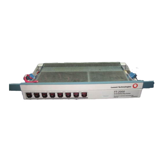
Lucent Technologies FT-2000 OC-48 Manuals
Manuals and User Guides for Lucent Technologies FT-2000 OC-48. We have
1
Lucent Technologies FT-2000 OC-48 manual available for free PDF download: User & Service Manual
Lucent Technologies FT-2000 OC-48 User & Service Manual (1578 pages)
Lightwave System Releases Through 7.2
Brand:
Lucent Technologies
| Category:
Network Hardware
| Size: 11 MB
Table of Contents
Figures
17
Table of Contents
17
1 System Introduction
57
OC-48 Add/Drop-Rings Terminal for Two-Fiber Rings
61
Major Features of Product Releases 1 through
64
2 Applications
70
Two-Fiber Bidirectional Ring Application
71
Folded Rings Evolving to Full Ring Networks
75
End-To-End Interface Mixing Application
77
OC-48 Hubbing Application
78
Tributary
79
Dual Ring Interworking Application
81
Dual Ring Interworking Application with the DDM-2000 OC-3 Multiplexer
83
DDM-2000 OC-3 Ring Transport Application
85
Dual-Wire Center Architecture Application
87
Broadband Service Transport Application
90
One-Way Video Distribution Application
94
Path-In-Line Architecture
96
Loop Feeder Network Application
98
Extra Traffic (Protection Line Access) for Restoration and Revenue Generation Application
100
0% Add/Drop Application
102
Wavelength Division Multiplexing Application
105
Operations Interworking Application
110
Gateway Network Element Application
114
Gateway Network Element Application
115
Add/Drop-Rings Terminal
115
And Later)
115
Synchronization Status Messages
116
FT-2000 Ring Environments
117
Platform Descriptions
119
Power Distribution and Fuse Panel
124
Low-Speed Shelf - System Controller (Without Circuit Pack Cover)- ED6G999-31, G5
125
Low-Speed Shelf - System Controller (Without Circuit Pack Cover) - ED6G999-32, G3
126
Permitted Slot Locations for the Quad Circuit Pack
128
Low-Speed Shelf - System Controller Circuit Pack Slot/Circuit Pack Code/Software Compatibility
130
Interconnection Panel (Low-Speed Shelf - System Controller) -ED6G999-32, G3
133
User Panel (Enhanced) 6G999-31, G5
134
User Panel 6G999-32, G3
135
High-Speed Shelf Circuit Pack Slot/Circuit Pack Code/Software Compatibility
139
Enhanced High-Speed Shelf Circuit Pack Slot/Circuit Pack Code/Software Compatibility
147
Power Distribution and Fuse Panel
155
Circuit Pack Cover)
156
Repeater Shelf - System Controller Circuit Pack Slot/Circuit Pack Code/Software Compatibility
158
User Panel (FT-2000 OC-48 Repeater Shelf) for Miscellaneous Mounting Only
161
Repeater Shelf - System Controller with Covers
162
Repeater Shelf - System Controller with Covers (FT-2000 OC-48 Repeater Shelf)
163
Fuse Panel
167
Low-Speed Shelf - System Controller (Without Circuit Pack Cover) - ED6G999-31, G5
168
Low-Speed Shelf - System Controller (Without Circuit Pack Cover) - ED6G999-32, G3
169
Permitted Slot Locations for the Quad Circuit Pack
170
Low-Speed Shelf - System Controller Circuit Pack Slot/Circuit Pack Code/Software Compatibility
172
Interconnection Panel (Low-Speed Shelf - System Controller)-ED6G999-31,G5
174
Low-Speed Shelf - System Controller (with Covers)
176
Condensed High-Speed Shelf
177
Pack Cover)
179
Enhanced High-Speed Shelf Circuit Pack Slot/Circuit Pack Code/Software Compatibility
180
Interconnection and Filter Panel
182
Bay Power Distribution
188
Miscellaneously-Mounted
189
Repeater Shelf Power Distribution
189
Shelf Power Distribution
190
Rings (D-Bay)
192
Power Dissipation and Current Drains
192
Controller
198
Control, Transmission, and Synchronization Interfaces
198
System Control Architecture for the
198
OC-48 Add/Drop-Rings Terminal
198
System Control Architecture for the
199
OC-48 Add/Drop-Rings Terminal for 2-Fiber Rings Transmission Block Diagram
201
Add/Drop-Rings Terminal
201
FT-2000 OC-48 Repeater Bay Transmission
205
Block Diagram
205
Oc48 Regenr
205
High-Speed Shelf)
207
System Controller
207
Through Timed Synchronization
209
Through Timed Synchronization
210
Loop Timed Synchronization
211
Externally Timed Synchronization
213
Free Running/Free Running Configuration
217
Free Running/Through Timed Configuration
218
Externally Timed/Through Timed Configuration
219
Phase Locked/Phase Locked Configuration
220
Phase Locked/Phase Locked Configuration [LAA18 TG3 (DS1) Circuit Pack]
221
Externally Timed/Externally Timed Configuration
222
Example of a Ring Application with One Node Provisioned Free Running and All Other Nodes Provisioned through Timed (Without Timing Drops)
224
Example of a Ring Application with One Node Provisioned Free Running and All Other Nodes Provisioned Line Timed (Without Timing Drops)
225
Example of a Ring Application with One Node Provisioned Externally Timed and All Other Nodes Provisioned through Timed (Without Timing Drops)
227
Example of a Ring Application with One Node
227
Provisioned Externally Timed and All Other Nodes
227
Provisioned Externally Timed and All Other Nodes
228
Provisioned Line Timed (Without Timing Drops)
228
Example of a Ring Application with Two Nodes
229
Provisioned through Timed or Externally Timed
229
Timing Drops)
229
Example of a Ring Application with Three Nodes Provisioned Externally Timed and One Node Provisioned Line Timed (Without Timing Drops)
230
Example of a Ring Application with One Node Provisioned Externally Timed and All Other Nodes Provisioned Line Timed (with Two Timing Drops)
231
Example of a Ring Application with One Node Provisioned Externally Timed and All Other Nodes Provisioned through Timed (with Timing Drops)
232
Example of a Ring Application with One Node Provisioned Externally Timed and All Other Nodes Provisioned through Timed or Externally Timed (with Timing Drops)
233
Example of a Ring Application with All Nodes Provisioned Externally Timed (with Timing Drops)
235
Example of a Timing Loop Resulting from Incorrect Provisioning
236
Example of a Timing Loop Resulting from Inconsistent DS1
237
Timing Interfaces
237
Example of a Ring Application with All Nodes Provisioned Externally Timed (with External Timing Emulation Cable)
238
Filter Panel
241
6 Operations Interfaces
245
Remote Access Using the OC-48 Section Orderwire
253
Add/Drop-Rings Terminal
254
User Panel (Low Speed Shelf - System Controller and Repeater Shelf - System Controller) - Cabled Version (before 06/97)
255
User Panel (Low Speed Shelf - System Controller and Repeater Shelf - System Controller) - Plug-In-Type (after 06/97)
256
Filter Panel for the Enhanced High Speed Shelf
259
Power Indicating Panel for the Condensed High Speed Shelf
260
FT-LBA Miscellaneous Discrete Mapping
263
Table of Contents
276
Circuit Pack Descriptions
279
Circuit Packs and Compatible Software
282
SYSCTL Circuit Pack Block Diagram
286
SYSMEM (LAA25) Circuit Pack
289
SYSMEM Circuit Pack Block Diagram
291
Add/Drop-Rings Terminal
293
LNCTL (LAA28) Circuit Pack
295
LNCTL Circuit Pack Block Diagram
296
OHCTL (TERM) (LAA21 and LAA22) Circuit Pack
299
Pack Description
299
Faceplate LED
299
Purpose of Circuit
299
OHCTL (TERM) Circuit Pack Block Diagram
300
Detailed Description of Operation
300
General Description of Operation
300
Quick Reference Summary
303
TOHCTL (LAA26) Circuit Pack Description
304
Faceplate LED
304
Purpose of Circuit
304
Detailed Description of Operation
305
General Description of Operation
305
TOHCTL Circuit Pack Block Diagram
306
Quick Reference Summary
309
OW (LAA14) Circuit Pack
310
OW (LAA14) Circuit Pack Description
310
Faceplate
310
General Description of Operation
310
Purpose of Circuit
310
OW Circuit Pack Block Diagram
311
Detailed Description of Operation
311
Section Overhead Bytes
312
Quick Reference Summary
312
Transmission
313
DS3 (LAA2/LAA2B) Circuit Pack Description
313
DS3 Circuit Pack Block Diagram
314
STS1E (LAA4) Circuit Pack
322
Purpose of Circuit
322
STS1E Circuit Pack Block Diagram
323
Detailed Description of Operation
323
General Description of Operation
323
Quick Reference Summary
328
Purpose of Circuit
330
Faceplate LED
330
General Description of Operation
331
Detailed Description of Operation
331
OC3 (1.3 STD) LAA10 Circuit Pack Block Diagram
332
OC3 (1.3 STD) LAA10B Circuit Pack Block Diagram
332
Performance-Monitoring Parameters
337
Quick Reference Summary
338
IS3 (LAA5) Circuit Pack Description
340
Faceplate LED
340
Purpose of Circuit
340
Detailed Description of Operation
341
General Description of Operation
341
IS3 (1.3 STD) Circuit Pack Block Diagram
341
Quick Reference Summary
347
OC12 (1.3 STD) (T939A) Circuit Pack
349
T939A) Circuit Pack Description
349
Faceplate LED
349
Purpose of Circuit
349
General Description of Operation
350
Detailed Description of Operation
351
OC12 (1.3 STD) Circuit Pack Block Diagram
351
Overhead Bytes
352
Quick Reference Summary
356
LSSW (LAA12B) Circuit Pack
358
LSSW (LAA12B) Circuit Pack Description
358
Faceplate LED
358
Purpose of Circuit
358
General Description of Operation
359
Detailed Description of Operation
360
LSSW Circuit Pack Block Diagram
360
Quick Reference Summary
363
OC48 RCVR A/D (839B2, 839B4B, 839B5, and 839E5) Circuit Pack Description
364
Purpose of Circuit
364
Faceplate LED
365
Detailed Description of Operation
366
General Description of Operation
366
Overhead Bytes
366
OC48 RCVR A/D (839B2 and 839B4B) Circuit Pack Block Diagram
367
OC48 RCVR A/D (839B5 and 839E5) Circuit Pack Block Diagram
368
Quick Reference Summary
373
OC48 TRMTR A/D (739B_, 739C_, 739E_, 739G_, 739H_, 739J_, 739P5, 739R_, 739S_) Circuit Pack Description
375
Purpose of Circuit
375
Faceplate LED
376
Oc48 Trmtr A/D
376
General Description of Operation
377
Detailed Description of Operation
378
OC48 TRMTR A/D (739B2, 739B4, 739C2, 739J2, 739J3, 739J4, 739R2, and 739S2) Circuit Pack Block Diagram
378
OC48 TRMTR A/D Circuit Pack (739B5, 739C5, 739E[1-16], 739G[1-8], 739H[1-16], 739J5, 739P5, 739R5, and 739S5) Block Diagram
379
Quick Reference Summary
384
And 39S2) Circuit Pack
386
Faceplate LED
386
OC48 REGENR (39B1, 39B2, 39C1, 39C2, 39J2, 39R2, and 39S2) Circuit Pack Description
386
Purpose of Circuit
386
General Description of Operation
387
Detailed Description of Operation
388
OC48 REGENR Circuit Pack Block Diagram
388
Quick Reference Summary
392
TG3 (DS1) (LAA18) Circuit Pack
394
Synchronization
394
TG3 (DS1) (LAA18) Circuit Pack Description
394
TG3 (DS1) (LAA18) Circuit Pack Block Diagram
397
Administration and Provisioning
403
Administration
405
Memory Administration
405
Security
408
Port Security
409
User Login Security
410
Network Element Login Security
411
Password Aging
412
Version Recognition
408
Software Upgrades
413
Cross-Connections
415
Cross-Connect Rules
415
1-Way-DRI Cross-Connections at an
424
Cross-Connections
424
Limited STS-1 Cross-Connections
428
Limited STS-1 Cross-Connections Across and STS-3
429
Cross-Connections
432
Extra Traffic Capability
442
Rolling Cross-Connections
444
Cross-Connection Inputs
445
Example of 1-Way and 2-Way STS-1 Cross-Connections in a 2-Fiber Bidirectional Ring
455
Cross-Connection Examples
455
STS-1 Cross-Connection Worksheet
459
Example of 1-Way and 2-Way Cross-Connections in a 2-Fiber Bidirectional Ring
460
STS-3 Cross-Connection Worksheet
464
Example of STS-1 1-Way-DRI Cross-Connections in a 2-Fiber Bidirectional Ring
465
Example of STS-3 1-Way-DRI Cross-Connections in a 2-Fiber Bidirectional Ring
468
Example of 1-Way and 1-Way-DRI Cross-Connections in Video Applications
471
Example of Rolling STS-1 Cross-Connections in a 2-Fiber Bidirectional Ring
476
Example of Rolling STS-3 Cross-Connections in a 2-Fiber Bidirectional Ring
478
Example of STS-1 Cross-Connections in a 2-Fiber Bidirectional Ring
479
Example of STS-3 Cross-Connections in a 2-Fiber Bidirectional Ring
482
Example of Limited STS-1 Cross-Connections in a 2-Fiber Bidirectional Ring
485
Data Communications Channel Assignment Inputs
488
Data Communications Channel Assignment Examples
490
Example of OC-3 DCC Connectivity
490
DCC Assignment Inputs
493
Data Communications Channel Assignment Examples
495
Example of OC-12 DCC Connectivity
495
Access Identifiers
497
OC-48 Repeater Bay Input Values
497
OC-48 Repeater Bay Output Values
497
Provisionable Parameters and Original Values
502
General
502
FT-2000 OC-48 Add/Drop-Rings Terminal
503
Provisioning
502
Local Provisioning
513
OC-48 Add/Drop-Rings Terminal
513
OC-48 Repeater Bay
541
Pre-Provisioning Circuit Packs
547
Provisioning on Circuit Pack Replacement
547
Circuit Pack Slot and Low-Speed Port Provisioning States
548
Maintenance Description
551
Remote Maintenance Philosophy
553
Overview
553
Maintenance Signals
554
OC-48 Add/Drop-Rings Terminal Maintenance Signals (When Interfacing with DS3 Signals)
556
OC-48 Add/Drop-Rings Terminal Maintenance Signals
557
OC-48 Add/Drop-Rings Terminal Maintenance Signals for through Tributaries
558
FT-2000 OC-48 Repeater Bay Maintenance Signals
559
Fault Detection, Isolation, and Reporting
560
Incoming Signals and Monitored Conditions
561
Protection Switching
583
High-Speed Protection
583
General
583
2-Fiber Ring Protection Switching Architecture
584
Bidirectional Line-Switched 2-Fiber Ring (Normal Transmission)
587
2-Fiber Ring Protection Switching Example
587
Single and Double Failure States
592
Single and Double Failures
592
Electrical Low Speed Protection
595
Electrical Low Speed Protection Switching Priorities
596
Electrical Low Speed Protection Switching
597
Optical Low Speed Protection Switching Priorities
599
General
599
Optical Low Speed Protection - (OC-3)
599
Optical Low Speed Protection Switching Architecture
601
Optical Low Speed Protection Switching Example
602
1+1 OC-3 Line (Fiber Cut)
603
Optical Low Speed Protection Switching Priorities
604
General
604
Optical Low Speed Protection - (OC-12)
604
Optical Low Speed Protection Switching
606
Optical Low Speed Protection Switching Architecture
606
Optical Low Speed Protection Switching Example
607
Dual Ring Interworking Protection Switching Priorities
609
Dual Ring Interworking Protection
609
Dual Ring Interworking Circuit (Normal Transmission)
611
Dual Ring Interworking Circuit (Node Failure in Other Ring)
613
Dual Ring Interworking Circuit (Primary Node Failure)
615
Dual Ring Interworking Circuit (Secondary Node Failure)
616
Synchronization Hardware Protection Switching Priorities
617
General
617
Synchronization Hardware Protection
617
Synchronization Protection
617
TG3 (DS1) Circuit Pack Protection
618
DS1 Reference Protection
620
Synchronization Reference Protection Switching Priorities
620
Synchronization Reference Protection
620
OC-48 Line Reference Protection
621
Synchronization Mode Protection Switching Priorities
623
Synchronization Mode Protection
623
Loopbacks
624
High-Speed (OC-48)
625
Tests
626
Auto Turnup
626
TRMTR Circuit Packs
627
Regenerator Self-Test
629
Operations Interface Tests
630
Circuit Provisioning Audits
631
Performance Monitoring
633
SONET Performance Parameters
633
Optical Parameters
635
OC-3/OC-12 Optical Parameters
636
STS-48/STS-12/STS-3 Section Parameters
637
OC-48/OC-12/OC-3 Line Parameters
638
Path Parameters
639
Section/Line Parameters
640
DS3 Line/Path
641
Performance-Monitoring Data Storage and Reports
642
Performance Monitoring During Failed Conditions
642
Performance-Monitoring Parameter Thresholds
643
Threshold Crossing Alert Transmission to an os
643
Reports
644
Active Alarms and Status
644
Provisioning Reports
645
Performance Monitoring
646
State
646
Version/Equipment List
647
Synchronization Report
647
Technical Specifications
649
Transmission Medium
653
Optical Connector Interfaces
653
Overview
653
Optical Line Interface
653
Lightguide Jumpers
654
Optical Source
654
Optical Detector
654
Optical Safety (CDRH Classification)
654
Operating Wavelength
655
Optical Dispersion
656
Optical Return Loss
656
OC-48 Loss Budget Specifications
657
Optical Line Loss Budgets
657
FT-2000 OC-48 Lightwave System
657
Outside Plant Loss
657
Loss Budget Specifications for 739E/G[1-8] OC48
658
Loss Budget Specifications for 739E/G[9-16] OC48
659
Loss Budget Specifications for 739H[1-8] OC48
660
Loss Budget Specifications for 739H[9-16] OC48
661
Loss Budget Specifications for 839B5 and 839E5 OC48 RCVR Circuit Packs
661
Optical System Interfaces
662
OC-48 Lightwave System and FT-Lightwave Booster Amplifier Loss Budgets
663
OC-48 Lightwave System and FT-Lightwave Booster Amplifier
663
OC-48 Lightwave System and Wavelength Division Multiplexing Systems Loss Budgets
664
OC-48 Lightwave System and Wavelength Division Multiplexing Systems
664
OC-48 Lightwave System with Wavelength Division Multiplexing Systems and FT-LBA Loss Budgets
665
OC-48 Lightwave System with Wavelength Division Multiplexing and FT-LBA Systems
665
Transmission Distances
666
OC-48 Lightwave System Without Optical Amplifiers
666
Transmission Distances Without Optical Amplifiers
666
Transmission Distances with the FT-Lightwave Booster Amplifier
667
OC-48 Lightwave System and the FT-Lightwave Booster Amplifier
667
Capacity
668
Transmission Distances with Wavelength Division Multiplexing and the FT-LBA
668
OC-48 Lightwave System with Wavelength Division Multiplexing and FT-LBA Systems
668
DS3 Access
669
Transmission Characteristics
669
EC-1 Access
670
OC-3 Access
671
Optical Line Interface
671
Optical Connector Interfaces
671
Transmission Medium
671
Lightguide Jumpers
671
Optical Source
671
Optical Detector
672
Optical Safety (BRH Classification)
672
Operating Wavelength
672
Spectral Width
672
Optical Dispersion
672
OC-3 Line Loss Budgets
672
IS-3 Access
674
Optical Line Interface
674
Optical Connector Interfaces
674
Transmission Medium
674
Lightguide Jumpers
674
Optical Source
674
Optical Detector
674
Optical Safety (BRH Classification)
675
Operating Wavelength
675
Spectral Width
675
Optical Dispersion
675
IS-3 Line Loss Budgets
676
OC-12 Access
677
Optical Line Interface
677
Optical Connector Interfaces
677
Transmission Medium
677
Lightguide Jumpers
677
Optical Source
677
Optical Detector
677
Optical Safety (BRH Classification)
678
Operating Wavelength
678
Spectral Width
678
Optical Dispersion
678
OC-12 Line Loss Budgets
679
Maximum Distances
680
Transmission Delay
680
OC-3 to IS-3 Interface Interconnection
680
Protection Switching (OC-3, OC-12, OC-48 Lines)
681
Electrical Line Buildout Specifications
682
Common Coaxial Cable Interoffice Cross-Connect Options for DS-3 and STS-1E
683
Cable Access
683
Power Specifications
684
Bay/Shelf Dimensions
685
Circuit Pack Dimensions
687
Floor Loading Specifications
690
Environmental Specifications
690
Craft Interface Terminal
691
Personal Computer Requirements
691
ASCII-Based Terminal Requirements
693
Modem Requirements
693
Operations Interfaces
694
TL1/X.25 Interface
695
General
695
TL1/X.25 Interface - LAPB Link Layer Parameters
697
TL1/X.25 Interface - X.25 Packet Layer Parameters
697
TL1/X.25 Interface - EIA-232D Pin Connections
698
Craft Interface Terminal Usage
705
Overview
709
Cpro-2000 Cross-Reference Procedures
710
FT-2000 CIT-PC Software Introduction
711
Inputs
711
Notice Frames, Confirmation Requests, and Aborting Commands
712
Context-Sensitive Help
713
CIT Function Keys
713
PC Screen Header Line
715
Release 5 Inputs (Commands) Menu for
724
Outputs
746
Examples of Reports [Generated by Various Inputs (Commands)]
747
Example 1 - SECURITY-Retrieve-Active-User
747
Example 2 - FAULT-Retrieve-Alarm
749
Example 3 - CONFIGURATION-Retrieve-Assignment-DCC
751
Example 4 - CONFIGURATION-Retrieve-Attribute-Alarm
752
Example 5 - CONFIGURATION-Retrieve-Attribute-Control
753
Example 6 - CONFIGURATION-Retrieve-Attribute-Environment
754
Example 7 - CONFIGURATION-Retrieve-Circuit-STS1
755
Example 8 - CONFIGURATION-Retrieve-Circuit-STS3
758
Example 9 - CONFIGURATION-Retrieve-Crossconnection-STS1
760
Example 10 - CONFIGURATION-Retrieve-Crossconnection-STS3
762
Example 11 - CONFIGURATION-Retrieve-Crossconnection-All
767
Example 12 - CONFIGURATION-Retrieve-Date
770
Example 13 - CONFIGURATION-Retrieve-EC1
771
Example 14 - CONFIGURATION-Retrieve-Equipment
772
Example 15 - SECURITY-Retrieve-Far End Communications
774
Example 16 - FAULT-Retrieve-History
776
Example 17 - SECURITY-Retrieve-Login
777
Example 18 - CONFIGURATION-Retrieve-Low Speed
779
Example 19 - CONFIGURATION-Retrieve-Map-Network
780
Example 20 - CONFIGURATION-Retrieve-Map-Ring
781
Example 21 - FAULT-Retrieve-Network Alarms
784
Example 22 - SECURITY-Retrieve-Network Element
787
Example 23 - CONFIGURATION-Retrieve-OC3
791
Example 24 - CONFIGURATION-Retrieve-OC48
793
Example 25 - CONFIGURATION-Retrieve-Path-Trace
796
Example 26 - PERFORMANCE-Retrieve-PM-EC1
799
Example 27 - PERFORMANCE-Retrieve-PM-Line
801
Example 28 - PERFORMANCE-Retrieve-PM Mode-T3
805
Example 29 - PERFORMANCE-Retrieve-PM-Optics
806
Example 30 - PERFORMANCE-Retrieve-PM-Section
808
Example 31 - PERFORMANCE-Retrieve-PM-Start Time
810
Example 32 - PERFORMANCE-Retrieve-PM-STS1
811
Example 33 - PERFORMANCE-Retrieve-PM-T3
815
Example 34 - PERFORMANCE-Retrieve-PM-TCA
818
Example 35 - PERFORMANCE-Retrieve-PM Threshold-EC1
820
Example 36 - PERFORMANCE-Retrieve-PM Threshold-Line
823
Example 37 - PERFORMANCE-Retrieve-PM Threshold-Optics
825
Example 38 - PERFORMANCE-Retrieve-PM Threshold-Section
827
Example 39 - PERFORMANCE-Retrieve-PM Threshold-STS1
830
Example 40 - PERFORMANCE-Retrieve-PM Threshold-T3
833
Example 41 - CONFIGURATION-Retrieve-Protection-Line
836
Example 42 - CONFIGURATION-Retrieve-Protection-Low Speed
839
Example 43 - SECURITY-Retrieve-Security-Network Element
840
Example 44 - SECURITY-Retrieve-Security-Port
841
Example 45 - CONFIGURATION-Retrieve-Squelch Map-STS1
843
Example 46 - CONFIGURATION-Retrieve-Squelch Map-STS3
844
Example 47 - FAULT-Retrieve-State
845
Example 48 - CONFIGURATION-Retrieve-Synchronization
852
Example 49 - CONFIGURATION-Retrieve-T3
854
Example 50 - CONFIGURATION - Retrieve-Timeslot-STS1
856
Example 51 - CONFIGURATION-Retrieve-Timeslot-STS3
858
CIT Tutorial Using CIT-PC Software
860
Releases 2, 4, and 6 Inputs (Commands) Menu for
868
Add/Drop-Rings Terminal)
955
Add/Drop-Rings Terminal)
956
Add/Drop-Rings Terminal)
959
Add/Drop-Rings Terminal
982
Enhanced High-Speed Shelf
1177
Add/Drop-Rings Terminal
1196
Repeater Bay)
1346
Add/Drop-Rings Terminal
1348
Repeater Bay
1348
Add/Drop-Rings Terminal
1351
Add/Drop-Rings Terminal
1356
OC-48 Repeater Bay
1361
Repeater Bay/Shelf
1366
Interconnection Panel
1447
A Sonet Overview
1531
Overview
1533
History
1533
Basic Purpose
1534
Technical Overview
1534
SONET Signal Hierarchy
1534
SONET Layers
1536
SONET Frame Structure
1538
Section Overhead
1538
Line Overhead
1539
Path Overhead
1540
VT Path Overhead
1541
SONET Multiplexing Procedure
1542
SONET Demultiplexing Procedure
1544
SONET Digital Multiplexing Schemes
1547
Asynchronous Multiplexing
1547
Synchronous Multiplexing
1548
Virtual Tributary Signals
1548
Concatenated Mode
1549
SONET Interface
1550
SONET Payloads
1551
Higher Rate Transport
1552
Conclusion
1552
Advertisement
Advertisement
Related Products
Lucent Technologies CellPipe SDSU
Lucent Technologies cvMAX-100
Lucent Technologies LambdaXtreme
Lucent Technologies PacketStar PSAX 20
Lucent Technologies Stinger
Lucent Technologies Stinger MRT
Lucent Technologies Stinger MRT-AD-36S
Lucent Technologies Stinger MRT-AD-36S-2DS3
Lucent Technologies Stinger MRT-AD-36S-2OC3
Lucent Technologies Stinger MRT-AD-36S-4E1
Lucent Technologies Categories
Telephone
Switch
Conference System
Software
Telephone System
More Lucent Technologies Manuals
Login
Sign In
OR
Sign in with Facebook
Sign in with Google
Upload manual
Upload from disk
Upload from URL