Advertisement
Quick Links
SCOPE OF MANUAL
This manual provides instructions for installing and using
the HR-RED (High Resolution Remote Electronic Display) .
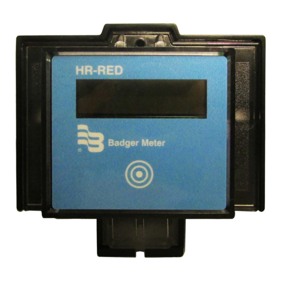
Product Description
The HR-RED is an electronic display designed to provide remote
visual readings when connected directly to Badger Meter®
Recordall® Disc, Turbo, Compound, and Fire Series meters
equipped with high resolution (HR) encoders—HR-E®, HR-E LCD,
HR-E LCD 4-20—or E-Series® Ultrasonic meters that are not easily
accessible or are in difficult to read locations. Installations such
as those inside houses or buildings, meter vaults, or dangerous
industrial locations are ideal for the HR-RED.
For additional information and product specifications, refer to the
HR-RED product data sheet, available in the Resource Library
at www.badgermeter.com.
STANDARD COMPONENTS
HR-RED Kit 64466-002
•
Strain relief ring
•
Three (3) connectors for wires
•
Torx® seal screw
•
Unit of measure adhesive label
Installation Tools
The following customer-supplied tools are recommended for installing the HR-RED. Items with a part number are available
from Badger Meter.
•
Electric drill
•
3/16 in. carbide tip masonry drill bits
•
Screw driver
•
59983-001 Crimping tool
•
59989-001 Cable stripper
•
59991-001 Wire cutting pliers
Wire Options
(if cable supplied with the meter/encoder is not sufficient)
•
64153-003 One (1) ft Belden® cable
•
68307-001 Nine (9) in. Twist Tight® connector cable
•
66488-007 Ten (10) in. Nicor® connector cable
DSY-UM-02471-EN-01 (November 2017)
HR-RED
High Resolution Remote Electronic Display
Installation Data
Advertisement

Related Manuals for Badger Meter HR-RED


Summary of Contents for Badger Meter HR-RED
- Page 1 • Torx® seal screw • Unit of measure adhesive label Installation Tools The following customer-supplied tools are recommended for installing the HR-RED. Items with a part number are available from Badger Meter. • Electric drill • 3/16 in. carbide tip masonry drill bits •...
- Page 2 Maximum cable length between the meter and the HR-RED is 2000 feet. Using the HR-RED base as a template, mark the mounting hole locations on the wall where the unit will be mounted. Drill the mounting holes at the marked locations and secure the base to the wall. (Mounting hardware is customer supplied.)
- Page 3 HR-RED records correctly to confirm successful installation. OTEE: If the meter is installed backwards, the encoder will not send a signal to the HR-RED. Check to make sure the flow arrow on the meter is pointing in the direction of water flow.
- Page 4 The Americas | Badger Meter | 4545 West Brown Deer Rd | PO Box 245036 | Milwaukee, WI 53224-9536 | 800-876-3837 | 414-355-0400 México | Badger Meter de las Americas, S.A. de C.V. | Pedro Luis Ogazón N°32 | Esq. Angelina N°24 | Colonia Guadalupe Inn | CP 01050 | México, DF | México | +52-55-5662-0882 Europe, Eastern Europe Branch Office (for Poland, Latvia, Lithuania, Estonia, Ukraine, Belarus) | Badger Meter Europe | ul.