Table of Contents

Related Manuals for Vision & Control TO30/9.1-85-F10-B-RF


Summary of Contents for Vision & Control TO30/9.1-85-F10-B-RF
- Page 1 VISION & CONTROL Instructions for Use Instructions for Use TO30/9.1-85-F10-B-RF TO30/9.1-85-F10-B-RF Telecentric measurement lens Telecentric measurement lens 999.995.930.10-en-2.2 © Vision & Control GmbH 2019...
- Page 2 Impress Publisher / Manufacturer Vision & Control GmbH Mittelbergstraße 16 98527 Suhl, Germany Telephone: +49 (0) 3681 7974-0 Telefax: +49 (0) 3681 7974-33 www.vision-control.com Name of the document 999.995.930.10-en-2.2 Date of first issue 22.10.2018 Date modified 2019-09-26 Copyright © Vision & Control GmbH 2019 Copyright It is forbidden to pass this document on to third parties, reproduce and communicate its contents in as far as this has not been expressly authorized.
- Page 3 Validity These instructions for use are valid for the following device: Device Order no. TO30/9.1-85-F10-B-RF 2-05-553 Product Identification Designation Description Telecentric measurement lens Maximum object field diameter in mm Maximum image sensor diagonal in mm Working distance in mm Fixed aperture: F10...
-
Page 4: Table Of Contents
TO30/9.1-85-F10-B-RF Table of Contents TABLE OF CONTENTS 1 Information about the Instructions of Use..........6 1.1 Intended Use....................6 1.2 Improper Use....................7 1.3 Qualified Personnel..................7 1.4 Warranty and Liability...................8 2 Safety......................9 2.1 Presentation of Safety Instructions.............. 9 2.2 Safe Handling of the Device..............10 3 Scope of Delivery and Accessories............ - Page 5 TO30/9.1-85-F10-B-RF Table of Contents 6.2.1 Mounting at the clamping area............27 6.2.2 Mounting of filters................27 6.2.3 Mounting at the camera..............27 6.3 Configuration....................28 6.3.1 Setting the working distance.............. 28 7 Operation...................... 29 8 Maintenance and Service................30 8.1 Maintenance....................30 8.2 Service......................32 9 Disposal......................
-
Page 6: Information About The Instructions Of Use
TO30/9.1-85-F10-B-RF Information about the Instructions of Use 1 INFORMATION ABOUT THE INSTRUCTIONS OF This document contains technical information, important instructions for correct installation, commissioning and use, as well as product information which were up-to-date at the time of going to press. -
Page 7: Improper Use
TO30/9.1-85-F10-B-RF Information about the Instructions of Use 1.2 Improper Use All unintended use and all device-related activities not described in these instructions of use is to be deemed as unauthorised misuse outside the legal limits of indemnity of the manufacturer. -
Page 8: Warranty And Liability
TO30/9.1-85-F10-B-RF Information about the Instructions of Use 1.4 Warranty and Liability The contents of this document have been checked carefully and correspond to current legislation and best practise at the time of going to press. However, the manufacturer shall not be liable for any damage arising from the use of this edition of the manual, and rejects any warranty derived therefrom. -
Page 9: Safety
TO30/9.1-85-F10-B-RF Safety 2 SAFETY 2.1 Presentation of Safety Instructions Each safety instruction is introduced by a key word and colour highlighted. The key word indicates the degree of danger. The danger and its cause are described, and then the measures to prevent conceivable consequences of the danger. -
Page 10: Safe Handling Of The Device
TO30/9.1-85-F10-B-RF Safety 2.2 Safe Handling of the Device Read the following applicable safety instructions carefully and completely. Follow the instructions for your own safety, the safety of other people, and to avoid damage to the device and the connected technical equipment. Hazards going beyond the general safety instructions are referred to separately at the relevant points in this manual. -
Page 11: Scope Of Delivery And Accessories
Scope of Delivery and Accessories 3 SCOPE OF DELIVERY AND ACCESSORIES 3.1 Scope of Delivery Designation Quantity Device TO30/9.1-85-F10-B-RF Covering cap Instructions for Use TO30/9.1-85-F10-B-RF 3.2 Accessories The following accessories are available for the lens. Lens holder Designation Description Order no. - Page 12 TO30/9.1-85-F10-B-RF Scope of Delivery and Accessories Beam Splitter Unit Designation Description Order no. STE30x30-VIS1 Beam splitter unit - merges the optical axis of 1-18-050 the lens or camera with the axis oft the lighting Adapter Adapter for attaching the STE30x30 to...
- Page 13 TO30/9.1-85-F10-B-RF Scope of Delivery and Accessories Filter for filter thread object-side Designation Description Order no. ND filter 0.6 Optical density 0.6 - 25% transmission, f-stop 2-91-150 M39x0.5 reduction 2 ND filter 1.2 Optical density 1.2 - 6.3% transmission, f-stop 2-91-160 M39x0.5...
-
Page 14: Device Description
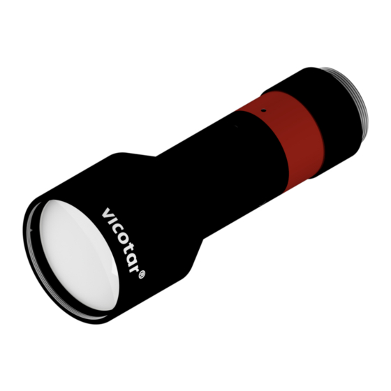
TO30/9.1-85-F10-B-RF Device Description 4 DEVICE DESCRIPTION 4.1 Device Views Image 1: Device view Filter thread M39x0.5 C-mount camera connection Type plate Contact edge camera 999.995.930.10-en-2.2 © Vision & Control GmbH 2019... -
Page 15: Notices On The Device
TO30/9.1-85-F10-B-RF Device Description 4.2 Notices on the device Type plate Type: TO30/9.1-85-FX-B SN.: XXXXXXXX Image 2: Type plate Position on the lens Device designation Serial number © Vision & Control GmbH 2019 999.995.930.10-en-2.2... -
Page 16: Technical Data
TO30/9.1-85-F10-B-RF Technical Data 5 TECHNICAL DATA 5.1 General Parameters Parameter Value Housing material Aluminium, black anodised Optical material Glass Housing dimensions Diameter: 42 mm Clamping diameter: 28 mm Filter thread object-side M39 x 0.5 Lens mount C-mount Flange focal distance 17.526 mm... - Page 17 TO30/9.1-85-F10-B-RF Technical Data Optimal sensor size ADVICE The illustrated image sensor serves as an overview. Other image sensors with image field diagonals up to 9.1 mm are also possible. 1/1.8" 1/3" 1/4" 7.1 mm 4.8 mm 3.4 mm Object fields at different sensor formats...
-
Page 18: Optical Parameters
TO30/9.1-85-F10-B-RF Technical Data 5.2 Optical Parameters Parameter Value Spectral range 450 nm - 660 nm (visible light) optimized at 450 nm - 490 nm (blue light) Effective F-number Object-sided numerical aperture 0.050 Image-sided numerical aperture 0.015 Image scale 0.308 Working distance 85 ±... -
Page 19: Telecentricity
TO30/9.1-85-F10-B-RF Technical Data 5.2.4 Telecentricity Parameter Value Telecentricity type Object-sided Object-side telecentricity angle φ < 0.05 ° Image resizing at 1 mm object depth < 1.75 μm Image resizing at 2 mm object depth < 3.50 μm © Vision & Control GmbH 2019... -
Page 20: Optical Characteristics (Design Data)
TO30/9.1-85-F10-B-RF Technical Data 5.3 Optical characteristics (design data) 2/3" Image 3: Illustrative sketch of optical characteristics Image plane Image field Image centre (axis points) Line grid tangential (T) Image sensor Line grid sagittal (S) ADVICE The following design data was determined with the optics design software Zemax. -
Page 21: Mtf Depending On The Spatial Frequency
TO30/9.1-85-F10-B-RF Technical Data 5.3.1 MTF depending on the Spatial Frequency Object Field Height [mm]: 12 T 15 T Diff. Limit 0 T/S 12 S 15 S Spatial Frequency [LP/mm] Image 4: MTF - spatial frequency dependent (470 nm, F10) 5.3.2 MTF depending on the Object Field... -
Page 22: Lateral Chromatic Aberration
TO30/9.1-85-F10-B-RF Technical Data 5.3.3 Lateral Chromatic Aberration Wavelength: 470 nm 490 nm 450 nm Deviation [µm] Image 6: Lateral chromatic aberration - wavelength dependent 5.3.4 Longitudinal Chromatic Aberration Deviation [µm] Image 7: Longitudinal chromatic aberration - wavelength dependent 999.995.930.10-en-2.2 © Vision & Control GmbH 2019... -
Page 23: Distortion
TO30/9.1-85-F10-B-RF Technical Data 5.3.5 Distortion Wavelength: 470 nm 490 nm 450 nm - 1.0 Distortion [%] Image 8: Distortion - wavelength dependent 5.3.6 Vignetting 14 15 Object Field Height [mm] Image 9: Vignetting © Vision & Control GmbH 2019 999.995.930.10-en-2.2... -
Page 24: Conditions For Operation, Storage And Transport
TO30/9.1-85-F10-B-RF Technical Data 5.4 Conditions for Operation, Storage and Transport NOTICE The device is shock and vibration sensitive. Loads of this type lead to loss of performance or to the destruction of the device. Store and transport the device in shock-proof box, if possible in the original packaging. -
Page 25: Technical Drawings
TO30/9.1-85-F10-B-RF Technical Data 5.5 Technical Drawings Ø 29.4 C-mount Contact edge camera Clamping area Ø 28 g7 Filter thread M39 x 0.5 Ø 42 Object The dimensions given are in millimetres. Image 10: Technical Drawings © Vision & Control GmbH 2019... -
Page 26: Commissioning
TO30/9.1-85-F10-B-RF Commissioning 6 COMMISSIONING 6.1 Unpacking The lens is locked in a rotary pack sleeve. 1. Unscrew the cap of the rotating pack sleeve. 2. Remove the lens. 3. Remove the cover caps only after complete installation and shortly before use at the place of use. -
Page 27: Mounting At The Clamping Area
TO30/9.1-85-F10-B-RF Commissioning 6.2.1 Mounting at the clamping area The assembly of the lens takes place at the clamping area (1). The appropriate mounting adapters are available as accessories. see "Lens holder", page 11 1. Loosen the socket head cap screws of the objective holder. -
Page 28: Configuration
TO30/9.1-85-F10-B-RF Commissioning 6.3 Configuration 6.3.1 Setting the working distance The lens has a fixed working distance. The distance is specified from the front edge of the lens to the test object. Mount the lens at this working distance above the test object. -
Page 29: Operation
TO30/9.1-85-F10-B-RF Operation 7 OPERATION ADVICE The front lens can be protected from foreign bodies by using the UV filter (protective glass). see "Filter for filter thread object-side", page 13 Keep the lens away from foreign objects (dusts, mist, water splashes or similar) during operation. -
Page 30: Maintenance And Service
TO30/9.1-85-F10-B-RF Maintenance and Service 8 MAINTENANCE AND SERVICE 8.1 Maintenance The device is maintenance-free. Depending on the operating environment, it may have to be cleaned. Perform cleaning only if the imaging characteristics are noticeably disrupted. Only clean surfaces accessible from the outside. Do not open the lens. - Page 31 TO30/9.1-85-F10-B-RF Maintenance and Service Cleaning the optical surfaces NOTICE Follow the specified cleaning sequence. Never use dry cloths for cleaning. This allows dust and other contaminants to be rubbed into the lens surface, thereby damaging it. 1. Remove non-adherent dusts with a blower brush or cleaned compressed air.
-
Page 32: Service
TO30/9.1-85-F10-B-RF Maintenance and Service 8.2 Service Technical Support Please contact our technical support if you have any technical questions concerning our products. We will be glad to be of service: Monday to Thursday 8:00 to 17:00, and Friday 8:00 to 15:00. -
Page 33: Disposal
TO30/9.1-85-F10-B-RF Disposal 9 DISPOSAL The device and its accessories and packaging must be sent to environmentally compatible recycling. Disposal, including that of individual components, must also always be in a way that does not harm the environment, that is it must be done in accordance with the currently valid legal regulations. - Page 34 TO30/9.1-85-F10-B-RF 999.995.930.10-en-2.2 © Vision & Control GmbH 2019...
- Page 35 TO30/9.1-85-F10-B-RF © Vision & Control GmbH 2019 999.995.930.10-en-2.2...
- Page 36 Vision & Control GmbH Mittelbergstraße 16 98527 Suhl, Germany Telephone +49 (0) 3681 7974-0 Telefax: +49 (0) 3681 7974-33 Vision & Control GmbH...
Need help?
Do you have a question about the TO30/9.1-85-F10-B-RF and is the answer not in the manual?
Questions and answers