Table of Contents
Advertisement
Advertisement
Table of Contents

Related Manuals for SMC Networks Thermo-con INR-244-639

Summary of Contents for SMC Networks Thermo-con INR-244-639
- Page 1 Artisan Technology Group is your source for quality new and certified-used/pre-owned equipment SERVICE CENTER REPAIRS WE BUY USED EQUIPMENT • FAST SHIPPING AND DELIVERY Experienced engineers and technicians on staff Sell your excess, underutilized, and idle used equipment at our full-service, in-house repair center We also offer credit for buy-backs and trade-ins •...
- Page 2 Thermo-con INR-244-639 18.June.2004 HEC-OM-H010-1 Version 1.0 Keep available whenever necessary.
-
Page 3: Table Of Contents
Contents Contents Page Introduction ------------------------------------------------------------------------------- 1-1 1.1 Scope and general description of use--------------------------------------------------------------------1-1 1.2 How to use operation manual -------------------------------------------------------------------------------1-1 1.3 Construction of operation manual--------------------------------------------------------------------------1-2 Safety Instructions--------------------------------------------------------------------- 2-1 2.1 Before using the Thermo-con--------------------------------------------------------------------------------2-1 2.1.1 Safety training -------------------------------------------------------------------------------------------------------------------------2-1 2.1.2 Identification of “Danger”, “Warning”, “Caution” and “Note” ------------------------------------------------------------2-1 2.2 Position of “Warning”... - Page 4 Contents 5.1.2 Piping and Label --------------------------------------------------------------------------------------------------------------------- 5-2 5.1.3 Air Filter--------------------------------------------------------------------------------------------------------------------------------- 5-2 5.2 Top view----------------------------------------------------------------------------------------------------------- 5-3 5.2.1 Operation panel ---------------------------------------------------------------------------------------------------------------------- 5-3 5.2.2 Display ---------------------------------------------------------------------------------------------------------------------------------- 5-3 5.2.3 Handle ----------------------------------------------------------------------------------------------------------------------------------- 5-4 5.2.4 Reservoir Cap ------------------------------------------------------------------------------------------------------------------------- 5-4 5.3 Left view----------------------------------------------------------------------------------------------------------- 5-5 5.4 Control Mode ---------------------------------------------------------------------------------------------------- 5-6 5.4.1 Auto Start ------------------------------------------------------------------------------------------------------------------------------ 5-6 5.4.2 Normal Control(Manual) ----------------------------------------------------------------------------------------------------------- 5-6 5.4.3 Normal Control(Communication) ----------------------------------------------------------------------------------------------- 5-6...
- Page 5 Contents 8.5.1 How to enter and return ------------------------------------------------------------------------------------------------------------8-8 8.5.2 Available mode in Level 3----------------------------------------------------------------------------------------------------------8-8 8.6 Detail of setting mode level ----------------------------------------------------------------------------------8-9 8.6.1 Setting mode, Level 1----------------------------------------------------------------------------------------------------------------------8-9 8.6.2 Setting mode, Level 2-------------------------------------------------------------------------------------------------------------8-12 8.6.3 Setting mode, Level 3-------------------------------------------------------------------------------------------------------------8-15 Alarm----------------------------------------------------------------------------------------- 9-1 9.1 How to Identify Alarm-------------------------------------------------------------------------------------------9-1 9.2 Alarm indication -------------------------------------------------------------------------------------------------9-2 9.3 How to reset alarm----------------------------------------------------------------------------------------------9-3...
- Page 6 Contents Figure List Page Fig. 2-1 Position of “Warning” label-------------------------------------------------------------------------------------------------------------- 2-4 Fig. 2-2 Legend of “Warning” label --------------------------------------------------------------------------------------------------------------- 2-4 Fig. 2-3 Position of “Caution” label--------------------------------------------------------------------------------------------------------------- 2-5 Fig. 2-4 Legend of “Caution” label A------------------------------------------------------------------------------------------------------------- 2-5 Fig. 2-5 Legend of “Caution” label B------------------------------------------------------------------------------------------------------------- 2-5 Fig.
- Page 7 Contents Table List Page Table 2-1 Division of DANGER, WARNING, CAUTION, and NOTE-------------------------------------------------------------------2-2 Table 2-2 Meaning of a symbol --------------------------------------------------------------------------------------------------------------------2-2 Table 2-3 Safety interlock list(Part 1)------------------------------------------------------------------------------------------------------------2-9 Table 2-4 Safety interlock list(Part 2)----------------------------------------------------------------------------------------------------------2-10 Table 6-1 Specifications ------------------------------------------------------------------------------------------------------------------------------6-1 Table 8-1 Available mode in Level 1--------------------------------------------------------------------------------------------------------------8-5 Table 8-2 Available mode in Level 2--------------------------------------------------------------------------------------------------------------8-7 Table 8-3 Available mode in Level 3--------------------------------------------------------------------------------------------------------------8-8 Table 9-1 Alarm information -------------------------------------------------------------------------------------------------------------------------9-1...
- Page 8 Contents Abbreviations Abbreviation (The order of ABC) Meaning Alternating Current Auto Tuning Chap. Chapter Colder Products Company Direct Current Electro Magnetic Interference EPDM Ethylene Propylene Diene Monomer Error International Electrotechnical Commission Liquid Crystal Display PE (Electricity) Protective Earthing PE (Material) Polyethylene Proportional,Integral,Differentiate Polyphenylene Sulfide...
-
Page 9: Introduction
The definition and construction of operation manual are described below. Scope and general description of use The operation manual applies to operation method of SMC-brand Thermo-con INR-244-639. Thermo-con is air-to-liquid heat exchanger to be used to control the temperature of the Apollo digital detectors in an X- Ray system. -
Page 10: Construction Of Operation Manual
Introduction Construction of operation manual 1) Chap. 1 Introduction The definition and use of operation manual are described. 2) Chap. 2 Safety Instructions Safety instruction, caution note, danger and warning, warning label and caution label and safety interlock used in this unit are described. 3) Chap.3 Caution on Installation The precautions for setting up and mounting this unit are described. -
Page 11: Safety Instructions
Safety Instructions Safety Instructions Before using the Thermo-con This chapter is dedicated for your safety during your relation with the unit. The Thermo-con is operated under high voltage. Therefore, not only those who operate the unit, but those who are in charge of service work related to the unit and who work nearby the unit should read carefully and thoroughly understand descriptions related to safety in this manual before starting the work. - Page 12 Safety Instructions Table2-1 Division of DANGER, WARNING, CAUTION, and NOTE These paragraphs document hazards that would cause serious or even fatal injuries to workers if you handle improperly or fail to obey items necessary to avoid hazards during operations. DANGER These paragraphs document hazards that might cause serious injuries to workers if you do not carry out appropriate procedure or fail to obey...
-
Page 13: Position Of "Warning" Label And "Caution" Label
Safety Instructions Position of “Warning” label and “Caution” label This unit contains is provided with “Warning” label and “Caution” label to keep its operator safe. Check the contents and position of these labels before starting the work. The unit shall be handled by only specialists. Transportation, installation and maintenance including dangerous works shall be done by persons who have full knowledge and experience on the unit and the system. -
Page 14: Position Of "Werning" Label
Safety Instructions 2.2.1 Position of “Warning” label “Warning” label Fig.2-1 Position of “Warning” label 80mm 40mm Fig.2-2 Legend of “Warning” label 06/18/04... -
Page 15: Position Of "Caution" Labels
Safety Instructions 2.2.2 Position of “Caution” labels “Caution” label B “Caution” label A Fig.2-3 Position of “Caution” label 80mm 40mm Fig.2-4 Legend of “Caution” label A 80mm 25mm Fig.2-5 Legend of “Caution” label B 06/18/04... -
Page 16: Position Of Ground Label
Safety Instructions 2.2.3 Position of Ground label Ground label Fig.2-6 Position of Ground label 10mm 10mm Fig.2-7 Legend of Ground label 06/18/04... -
Page 17: Position Of Labels
Safety Instructions 2.2.4 Position of labels 95 ± 2 26 ± 2 60 ± 2 40 ± 2 98 ± 2 135 ± 2 5 ± 2 31 ± 2 5 ± 2 Fig.2-8 Position of labels 06/18/04... -
Page 18: Precautions For Running(Safety Interlock)
Safety Instructions Precautions for running (safety interlock) This is the function to protect personal, to restrict operation, which may cause damage to this unit or facility around, and to remove dangers related with safety and sanitation. This unit has several interlock functions, which activates when danger operation or condition occurs to stop operation and make it safe. -
Page 19: Interlock List
Safety Instructions 2.3.1 Interlock list Table2-3 Safety interlock list (Part 1) Description Part Cause Overheat in Heat Detects abnormal heat (detection range=60±5deg.C) in Thermostat Exchanger Thermo-module. Switching power Detects abnormal current/voltage or heat (detection Thermostat supply failure range=105±5deg.C). Overheat in Heat Detects overheat in Heat Sink (detection Thermostat Sink... - Page 20 Safety Instructions Table2-4 Safety interlock list (Part 2) Description Condition of unit Indication and buzzer How to reset Error indication on display. Overheat in Heat Shuts off Switching power Restart power Exchanger supply supply (ERR14) Error indication on display. Switching power Shuts off Switching power Restart power supply failure...
-
Page 21: Caution On Installation
Caution on Installation Caution on Installation Pay special attention to keep safety of human body during installation and transportation of the unit. Only the trained person with knowledge and experience can perform the possibly dangerous work associated with installation, transportation and maintenance. -
Page 22: Mounting
Caution on Installation Air OUT Air IN 500mm or more 500mm or more Fig.3-1 Installation environment Mounting The Thermo-con is preferably mounted as follows. Use the foot attached to the Thermo-con for mounting. Then tighten M6 screws (bolts) or equivalent into 4 holes sized to 6.4mm on the parts marked with arrow for mounting. -
Page 23: Unit Overview
Unit Overview Unit Overview Model No. label and ETL’s label Model No. label and ETL’s label are attached to the unit and indicated as shown below. ETL’s label Model No. label Fig.4-1 Position of Model No. label Fig.4-2 Legend of ETL’s label THERMO-CON I N R - 2 4 4 - 6 3 9 S E R . -
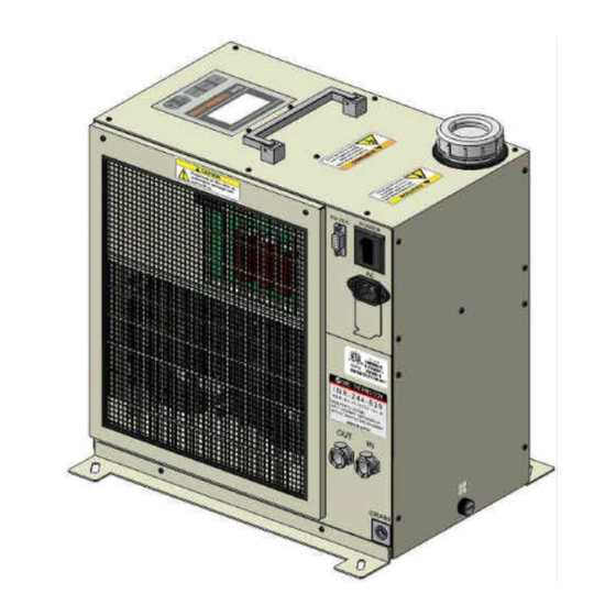
Page 24: Appearance
Unit Overview Appearance The appearance and the outline dimensions of the Thermo-con is as shown below. 243 283 (365) Fig.4-4 Outside drawings of Thermo-con 06/18/04... -
Page 25: Outline Of Operation
Unit Overview Outline of operation The unit is operated as explained below. 4.3.1 Electrical diagram The unit is equipped with electrical circuits as shown below. Membrane key display sheet Temp. Sensor CPU board Level Sensor Controller Thermostat Power supply RS-232C board Thermo-module DC5V, DC12V... -
Page 26: Mechanical System
Unit Overview 4.3.2 Mechanical system The unit is equipped with circulating liquid as shown below. Circulating liquid IN Reservoir DC Pump Heat Exchanger Plate Circulating liquid OUT Temp. Sensor Thermo-module Heat Sink DC Fan DC Fan Filter Fig.4-6 Circulating liquid circuit 06/18/04... -
Page 27: Names And Functions Of Components
Names and Functions of Components Names and Functions of Components The parts included into the unit have description and function individually. Right view The part attached on the right face of Thermo-con has description and function individually as shown below. Connectors Air Filter Piping and Label... -
Page 28: Piping And Label
Names and Functions of Components 5.1.2 Piping and Label ETL’s label ETL listing mark. Proof of agreement to standard. Model No. label Indicates model No., serial No., GEMS Part No., INPUT, and Date of Manufacture. Circulating liquid OUT Circulating liquid IN The port to discharge The port to return circulating liquid. - Page 29 Names and Functions of Components The performance decreases, and removes it, please when dust adheres to the air filter. We will recommend the removal of dust once every three months. Please remove dust with the cleaner, and use neither water nor the hot water.
-
Page 30: Top View
Names and Functions of Components Top view The parts attached to the top of Thermo-con have description and function individually as shown below. Operation panel Handle and Display Reservoir Cap Fig.5-5 Top view 5.2.1 Operation panel AT key Used to change set Used to start and stop value in each setting auto tuning. -
Page 31: Handle
Names and Functions of Components 5.2.3 Handle The handle should be raised up only to make the Thermo-con portable. Fig.5-8 Handle 5.2.4 Reservoir Cap Reservoir Cap Removed to supply circulating liquid before operation. Install prior to operation. Clockwise to open Counter-clockwise to close Gasket (Included) Put between Reservoir... -
Page 32: Left View
Names and Functions of Components Left view The part attached to the left of the Thermo-con has description and function individually as shown below. Fan guard For switching power supply cooling fan. The air is blown out from this side. Fig.5-10 Left vi ew 06/18/04... -
Page 33: Control Mode
Names and Functions of Components Control Mode Refer following for each control mode. 5.4.1 Auto Start Thermo-con must start displaying software version and turn into Auto Start mode after supplying power. [MODE] displays "Auto Start" and control starts with values below. P V <... -
Page 34: Pump Stop
Names and Functions of Components 5.4.4 Pump Stop Upon receiving communication command while normal control (communication) or safety default mode, mode moves to pump stop mode. This mode starts when alarm goes. During this mode, pump stops and power to DC P V <... -
Page 35: Specifications
Specifications Specifications The specifications of the Thermo-con is as shown below. Table6-1 Specifications Item Spec. 4.0 to 45.0deg.C(min. increment : manual setting 0.5deg.C Set Temp. range Communication setting 0.1deg.C) No dew condensation Set gradient temp. 10 to 60deg.C/h (min. increment : 5deg.C/h) Temp. - Page 36 Specifications Power supply voltage Single phase AC100-240V, 50/60Hz±3Hz Current consumption MAX 8A Inrush current 50A or less Over current suppressing 15A circuit protector Insulation resistance 50Mohm or more (DC500V, with surge absorber removed) Acoustic Noise MAX 52dBA(background of 35dBA, at a distance of 1m) Cooling style Forced air cooled style Auto tuning, Off set, Sensor fine adjustment, Temp.
-
Page 37: Preparation For Operation
Preparation for Operation Preparation for Operation The preparation, which is required before operation is as described below. Preparation for circulating liquid The piping for circulating liquid is connected as below. Confirm the piping for circulating liquid is located at right bottom of right face of the Thermo-con. -
Page 38: Supply Of Circulating Liquid
Preparation for Operation Supply of circulating liquid Reference The circulating liquid is supplied as described below. GEMS spec. Included in *Reference Chapter10.3 If aqueous solution with propylene glycol is used as circulating liquid, please refer GEMS spec #2352900PSP (include in Chapter10.3) Confirm power switch is turned off. -
Page 39: Check
Preparation for Operation Check The following checks shall be performed before operation. 7.4.1 Daily check Indication of display panel : Check temperature condition and confirm whether or not the alarm occurs. Filter : Confirm there is not attachment of the dust on the filter at suction port. A lot of attachment may impair performance of the filter. -
Page 40: Operation
Operation Operation This chapter describes the detailed information on how to operate. Condition after power up 1.Indication of software version When power is turned on, software version is indicated S OF T V E R S I ON on display panel for approx. 1 sec. (Ex. : G1.02) G 1 . -
Page 41: How To Operate
Operation How to operate 1.When any keys are pressed in [AutoStart], the manual operation becomes available. (The indication [AutoStart] disappears.) P V < 3 0 0 ° C # 1 0 ° C MO D E Au t o S t a r t THERMO-CON 2.The different 3 levels are available depending on the content, which needs to be set. - Page 42 Operation 5.[RET]key Used to fix the value changed by [ ]key. Press once again to return to current temp. indication. THERMO-CON 6.[AT]key Used to start auto tuning in auto tuning mode ( c ontrol operation mode : 2). When pressed during auto tuning, the auto tuning is suspended.
-
Page 43: Setting Mode, Level
Operation Setting Mode, Level 1 The method to enter to and return from setting mode Level 1 and which mode can be set in the level are explained below. 8.3.1 How to enter and return Press[SEL]key while power is turned on. Then, the indication on [MODE] is changed depending on the number of press and the data in the indicated mode can be set. - Page 44 Operation Table8-1 Available mode in Level 1 Setting range Modes Setting contents Default (Min. increment) Target Temp. 4.0 to 45.0deg.C Sets target temp. for control. 30.0 (No indication on display) (0.5deg.C) 10 to 60deg.C/h Set Gradient Temp. Sets target gradient temp. (5deg.C/h) Selects control operation mode among them below...
-
Page 45: How To Enter And Return
Operation 8.4 Setting mode, Level 2 The method to enter to and return from setting mode Level 2 and which mode can be set in the level are explained below. 8.4.1 How to enter and return Press[SEL]and[ ]keys at the same time while power is turned on. Then, the indication on [MODE] is changed depending on the number of press and the data in the indicated mode can be set. - Page 46 Operation Table8-2 Available mode in Level 2 Setting range Modes Setting contents Default (Min. increment) Fine Control of Sets the fine adjusting value to calibrate -9.99 to 9.99deg.C 0.00 Internal Sensor the internal temp. sensor. (0.01deg.C) Sets the fine adjusting value to calibrate Fine Control of -9.99 to 9.99deg.C the external temp.
-
Page 47: How To Enter And Return
Operation Setting mode, Level 3 The method to enter to and return from setting mode Level 3 and which mode can be set in the level are explained below. 8.5.1 How to enter and return Press[SEL]and[ ]keys at the same time while power is turned on. Then, the indication on [MODE] is changed depending on the number of press and the data in the indicated mode can be set. -
Page 48: Detail Of Setting Mode Level
Operation 8.6 Detail of setting mode level The each setting mode level is explained below in detail. 8.6.1 Setting mode, Level 1 1.Target temp. (no indication on display) Setting range : 4.0 to 45.0deg.C 2 5 . 0 ° C # 1 Min. - Page 49 Operation 5.Safety Default Set Gradient Setting range : 10 to 60deg.C/h S a f e t y D e f a u l t Min. increment : 5deg.C S e t G r a d i e n t Indicated content : Safety default gradient temp.(Ex. : MO D E <...
- Page 50 Operation 9.High Temp. Cutoff Setting range : 5.0 to 55.0deg.C Min. increment : 0.1deg.C H i g h T e m p . C u t o f f Indicated content : High temp. cutoff by internal temp. MO D E < 5 5 .
-
Page 51: Setting Mode, Level
Operation 8.6.2 Setting mode, Level 2 1.Fine Control of Internal Sensor Setting range : -9.99 to 9.99deg.C Min. increment : 0.01deg.C F i n e C o n t r o l I n t e r n a l S e n s o r Indicated content : Fine adjusting value for internal temp. - Page 52 Operation 5.I Constant Setting range : 1 to 999sec Min. increment : 1sec C o n s t a n t Indicated content : I constant(Ex. : 50sec) MOD E < s e c Function : Sets integral time used for PID control. THERMO-CON 6.D Constant Setting range : 0.0 to 99.9sec...
- Page 53 Operation 9.Overload Judging Time Setting range : 0 to 99min Min. increment : 1min O v e r l o a d J u d g i n g T i m e Indicated content : Overload judging time(Ex. : 0min) MOD E <...
-
Page 54: Setting Mode, Level
Operation 8.6.3 Setting mode, Level 3 1.Unit Number Setting range : 0-F(Hex decimal) Indicated content : Unit number(Ex. : 0) U n i t N u m b e r Function : Sets unit number used. This item is MO D E < applicable only when multiple units are used. -
Page 55: Alarm
Alarm Alarm The unit has various alarms explained below. How to Identify Alarm The alarm is identified as shown on the following table. Table9-1 Alarm information Indication Condition After alarm occurrence example After indication of software version, the error No.[ERR**] Power supply on starts flashing and then the contents of the error comes out. -
Page 56: Alarm Indication
Alarm Alarm indication Blink E R R 1 4 T h e r m o s t a t A l a r m MOD E S h u t O f f THERMO-CON Fig.9-1 Alarm indication in the event ERR14 arises Blink E R R 1 4 P B R a n g e... -
Page 57: How To Reset Alarm
Alarm How to reset alarm The alarm can be released in the following manner. Table9-2 Release of alarm Alarm code Description Manner of release ERR00 CPU hang-up Repair ERR01 CPU check error Initialization of EEPROM or stop and restart of power supply EEPROM wiring error ERR04... - Page 58 Alarm Code Description Contents Condition : Switching power supply has a problem or Thermo-module is short circuited. Abnormal DC ERR11 power voltage After alarm occurrence : The unit stops. Indication : [DC Power Voltage Failure] Condition : The temp. becomes higher than value set as high temp. cutoff. Default : 55.0deg.C High temp.
-
Page 59: Causes Of Alarm
Alarm Causes of Alarm Reason for setting and cause of alarm are explained as follows. Table9-4 Causes of Alarm Code Reason for alarm setting Cause ERR00, It detects failure of Thermo-con due to strong Strong noise and surge on Thermo-con makes noise, and prevents operation failure. -
Page 60: Troubleshooting
Alarm Troubleshooting Coping method when the alarm alerts is explained as follows. Table9-5 Troubleshooting Code Causes Repair (1) Move the Thermo-con to an environment with little (1) High level noise entered the noise, turn ON the power supply. Alarm is confirmed, we ERR00 power line, ground line, or temp. - Page 61 Alarm (1) High level noise entered the (1) Check the temperature unstable occurred by noise. ERR17 temp. sensor line. Please consult us if it causes noise. (1) Adjust PID value (proportional band, ARW value, (1) Capacity of circulating liquid ERR19 integral time and derivative time) of setting mode Level 2 circuit is too large.
-
Page 62: Appendix
Appendix Appendix The signal and shape of each connector and the method to calculate dew point are explained below. 10.1 Signal and style of connectors The signal and style of each connector attached to the Thermo-con are as shown on the table below. Table10-1 Signal and style of connectors Description Signal... -
Page 63: Calculation Of Dew Point(From Psychometric Chart)
Appendix 10.2 Calculation of dew point (from psychometric chart) 10 13 Temperature (deg.C) Fig.10-1 Psychometric chart Measure ambient temperature and humidity. Plot ambient temperature to the temperature of horizontal axis (Ex. 24 deg. C), and then draw perpendicular line. Obtain intersection (A) of the curve, which is almost equal to ambient temperature (Ex. - Page 64 Appendix 10.3 GEMS Specification #2352900PSP coolant specification Please refer to #2352900PSP of GEMS for the explanation according to abandonment. 06/18/04 10-3...
-
Page 65: Power Cable Specification
Appendix 10.4 Power cable specification Table10-2 Power cable specification Part name Condition which can be used Connector Part No.4782.0000 or 4782.0100(Schurter) or equivalent 250V or more in ratings voltage, copper wire of 1mm or more Cable in sectional area. Please use neither connector nor cable which does not satisfy the condition in Table 10-2. - Page 66 Artisan Technology Group is your source for quality new and certified-used/pre-owned equipment SERVICE CENTER REPAIRS WE BUY USED EQUIPMENT • FAST SHIPPING AND DELIVERY Experienced engineers and technicians on staff Sell your excess, underutilized, and idle used equipment at our full-service, in-house repair center We also offer credit for buy-backs and trade-ins •...
Need help?
Do you have a question about the Thermo-con INR-244-639 and is the answer not in the manual?
Questions and answers