
Related Manuals for American Panel MODULAR Series


Summary of Contents for American Panel MODULAR Series
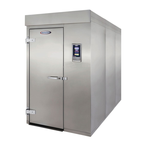
- Page 1 MODULAR SERIES BLAST CHILLERS & SHOCK FREEZERS AP20BC(F) AP20BC(F) AP26BC(F) AP26BC(F) AP36BC(F) AP36BC(F) AP46BC(F) AP46BC(F) Installation & User’s Manual...
-
Page 2: Table Of Contents
TABLE OF CONTENTS Warranty.................................. Unit Assembly................................ Checking for Proper Installation........................Specifications & Performance........................Modes Explained..............................Cycles Explained..............................- Soft Chill............................... - Hard Chill............................. - Shock Freeze............................- Defrost..............................- Thaw..............................- UV Sterilization..........................- Heated Probe............................. Factory Presets..............................Unit Operation..............................- Automatic Mode - Any Cycle...................... -
Page 3: Warranty
NONE NONE American Panel Corporation agrees to repair or replace at its option, FOB Factory, any part which proves to be defective due to defects in material or workmanship during the warranty period, providing the equipment has been properly installed, maintained and operated in accordance with the HurriChill™... - Page 4 Pre-Installation Locate the packing list (located in the accessory box) and ensure that all items listed are present and accounted for. If you determine that an item is missing please contact the factory prior to install. Electrical & Refrigeration Requirements Cabinet Cabinet Refrigeration Type...
- Page 5 Installation American Panel Corporation equipment has been shipped in a package designed to sufficiently protect from damage under normal shipping circumstances. Upon receiving the shipment, carefully inspect the package for visible damage and check the number of packages against the Bill of Lading. Notify the carrier immedi- ately of any shortage or damage to your shipment.
- Page 6 Reading the Floor Plan Two floor plans are included with the unit. One will be located in the accessory box and the other will be attached to the exterior door and frame assembly. Below is a sample floor plan. WALL PANEL MALE ROUT FEMALE...
- Page 7 Preparing the Installation Site (Cont’d) Determine if panels of considerable length can be transported through door openings, hallways and stairways. Check and determine if the floor has been treated prior to installing the unit. Note the location of any special accessories (heated relief vents, alarms, etc.) Cam-Lock Operation The cam-lock locking device is located in the perimeter edge of all panels.
-
Page 8: Unit Assembly
Unit Assembly NOTE: Please review the next section before starting assembly to ensure proper installation. 1. Place and level the floor panel. 2. Assemble the left, right and rear wall panels. Fasten panels to floor panel. 3. Place the evaporator assembly in the unit. - Page 9 Unit Assembly (Cont’d) 4. Install and fasten the door assembly to the walls and floor. 5. Place and fasten roof panel. Route control cables through roof panel cutout. 6. Install the air deflectors (per the instructions below) on the wall where the evaporator assembly will be installed. •...
- Page 10 Unit Assembly (Cont’d) 7. Position the coil assembly along the side wall behind the side of the door where the unit controller is located. 8. Secure the evaporator to the roof panel using the 3/8” screws, washers and nuts provided. 9.
- Page 11 Unit Assembly (Cont’d) 10. Use the provided screws to install the lower evaporator brackets. The wall panel is not pre-drilled and will need to be tapped in the field. 11. Use the provided screws to install the drain pan below the evaporator. Route the drain line and connect the drain pan to it.
- Page 12 Unit Assembly (Cont’d) 13. Mount the electric panel on top of the unit. 14. Make the electrical connections to the electrical panel. 15. Route the cables and connectors through the line set opening.
- Page 13 Unit Assembly (Cont’d) 16. Make the electrical connections inside the evaporator assembly. 16.1 If the blast chiller is equipped with pass-thru door, install the provided J-boxes and make the connections for the door heater and the door switch. The pig-tail cables coming from the controller will be clearly marked.
-
Page 14: Checking For Proper Installation
8. Operate the unit in Hard Chill, Manual Mode for a few minutes to verify temperature pull-down. NOTE: American Panel Corporation blast chillers are equipped with a short cycle protection. If the unit is stopped or the door is opened and closed during a chilling cycle more than once, the compressor will not start for 3 to 5 minutes. -
Page 15: Specifications & Performance
Specifications & Performance In blast chilling mode the units are capable of lowering the core temperature of the product from 160°F to 38°F within 90 minutes. In shock freeze mode the units are capable of lowering the core temperature of the product from 160°F to 0°F within 240 minutes. -
Page 16: Modes Explained
Modes Explained Each unit is capable of running in either an ‘Automatic’, ‘Manual’ or ‘A la Carte’ mode: • In ‘Automatic’ mode the unit will read the food temperature via the food probe and adjust the air temp- erature accordingly. NOTE: When using ‘Automatic’... -
Page 17: Shock Freeze
Cycles Explained (Cont’d) Shock Freeze: Use for all freezing needs. When using the Shock Freezing Cycle the ice crystals that form within the product are very small. The quality and the texture of the product is preserved. For that reason, the Shock Freeze Cycle is suitable even for delicate products such as sushi meat and prime meat cuts. -
Page 18: Factory Presets
Factory Presets FACTORY PRESETS AUTOMATIC MODE - QUICK REFERENCE CHART Setting Breaking Low Air High Air End Food Low Air High Air Low Air High Air Temp. Part 2 Part 2 Temp. Holding Holding Part 1 Part 1 Cycle Soft 28°F 35°F 40°F... -
Page 19: Unit Operation
Unit Operation Start any Cycle in Automatic Mode... -
Page 20: Manual Mode - Any Cycle
Unit Operation (Cont’d) Start any Cycle in Manual Mode... -
Page 21: A La Carte Mode - Any Cycle
Unit Operation (Cont’d) Start any Cycle in A la Carte Mode... -
Page 22: Home Screen
Unit Operation (Cont’d) Home Screen The home screen can be accessed by taping on the blank display, if the display is off, or by pressing the home button, if the controller is in one of the cycle screens. ① Soft Chill Button – Press to access Soft Chill Cycle Menu ②... -
Page 23: Automatic Mode Screen Explained
ID will show on the HACCP reports. The label of Food probe #... will display the temperature of the probe. One food probe is the standard configuration for all American Panel Corporation blast chillers, the controller supports up to 4 food probes. -
Page 24: Manual Mode Screen Explained
ID will show on the HACCP reports. The label of Food probe #... will display the temperature of the probe. One food probe is the standard configuration for all American Panel Corporation blast chillers, the controller supports up to 4 food probes. -
Page 25: A La Carte Screen Explained
One food probe is Status: the standard configuration for all American Panel “READY TO START” – unit in standby mode waiting for Corporation blast chillers, the controller supports up to the user to make a selection such as Start 4 food probes. -
Page 26: Haccp Download (Peer-To-Peer)
Unit Operation (Cont’d) HACCP Data Download - Peer-to-Peer If the blast chiller is equipped with the PC Communication Package, then the controller is set from the factory as a Wi-Fi access point. In this configuration the controller broadcasts an SSID such as blast-chiller-xxxxxxxxxxx-wha. To connect your Wi-Fi enabled device to the blast chiller controller do the following: 1. -
Page 27: Haccp Download (Via Wifi)
Unit Operation (Cont’d) HACCP Data Download via Wi-Fi network 1. Make sure the blast chiller controller is connected to a Wi-Fi network. 2. Open the web browser on a device that is connected to the same Wi-Fi network 3. In the address bar enter the IP address for the blast chiller or retrieve from favorites, see “Blast Chiller Controller Setup for Wi-Fi Network Connectivity”. -
Page 28: Wifi Connection
Unit Operation (Cont’d) Blast Chiller Controller Setup for Wi-Fi Network Connectivity 1. Connect your Wi-Fi enabled device to the blast chiller controller: a. Open the Wi-Fi connections tray b. Connect to the SSID blast-chiller-xxxxxxxxxxx-wha c. Open your web browser (Chrome is recommended) and enter the following in the address bar: 192.168.1.1 d. - Page 29 Unit Operation (Cont’d) Blast Chiller Controller Setup for Wi-Fi Network Connectivity (Cont’d) d. Reset power to the unit and allow few minutes for the controller to connect to theWi-Fi network. e. At the blast chiller controller, in the home screen push the settings button.
- Page 30 Unit Operation (Cont’d) Blast Chiller Controller Setup for Wi-Fi Network Connectivity (Cont’d) j. At your device, open your web browser and enter the noted IP address in the address bar. k. The home screen should appear, save the address in the favorites for quick access.
-
Page 31: Email Configuration
Unit Operation (Cont’d) Configure the controller to send e-mail alerts 1. Make sure that the blast chiller controller is connected to a Wi-Fi network with internet access; see “Blast Chiller Controller Set-up for Wi-Fi Network Connectivity”. -
Page 32: Uv Sterilization
Unit Operation (Cont’d) Run a UV Sterilization Cycle From the home screen, press the ‘UV Light’ button to choose the UV Light Cycle. Press the ‘Start’ button to begin the cycle Run a Defrost Cycle From the home screen, press the ‘Defrost’ button to choose the Defrost Cycle. Press the ‘Start’... -
Page 33: Download Haccp Data
Unit Operation (Cont’d) Download HACCP Data on USB Drive Insert the USB flash drive into the USB connector. Run an Thaw Cycle (Automatic/Manual) From the home screen, press the ‘Food Thaw’ button. Press the ‘Auto’ or ‘Manual’ tab. The unit will then await the operator to press start. Press the ‘Start’... -
Page 34: Maintenance Instructions
General Operating Instructions (Cont’d) Probing (for Thaw Cycle) Follow the methods below to ensure correct probing of the product: • Use the provided drill and drill bit to drill a hole into the frozen product. PC Package PC Communication Package The optional wireless pc communication package features: •... -
Page 35: Parts List
Part Numbers 990190 AIR PROBE ASSY 2-WIRE 100 OHM 91054-00 SWEEP GASKET KIT AP20 & AP26 1726 BUSHING PVC 3" 91054-01 SWEEP GASKET KIT AP36 990234 CAPACITOR FAN 91054-02 SWEEP GASKET KIT AP46 92249-00 CENTER AIR DEFLECTOR 994212 SWITCH MAGNETIC EVAP. DOOR 994220 CONTACTOR, POWER 2;...
Need help?
Do you have a question about the MODULAR Series and is the answer not in the manual?
Questions and answers