Table of Contents
Advertisement
Quick Links
ADCP-90-606
Rev C, May 2020
commscope.com
Content
INTRODUCTION . . . . . . . . . . . . . . . . . . . . . . . . . . . . . . . . . . . . . . . . . . . . . . . . . . . . . . . . . . . . . . . . . . . . . . . . . . . . . . . . . . . . . . . 2
Trademark Information . . . . . . . . . . . . . . . . . . . . . . . . . . . . . . . . . . . . . . . . . . . . . . . . . . . . . . . . . . . . . . . . . . . . . . . . . . . . . 2
Standards Certification. . . . . . . . . . . . . . . . . . . . . . . . . . . . . . . . . . . . . . . . . . . . . . . . . . . . . . . . . . . . . . . . . . . . . . . . . . . . . . 2
Admonishments . . . . . . . . . . . . . . . . . . . . . . . . . . . . . . . . . . . . . . . . . . . . . . . . . . . . . . . . . . . . . . . . . . . . . . . . . . . . . . . . . . . . 3
General Safety Precautions . . . . . . . . . . . . . . . . . . . . . . . . . . . . . . . . . . . . . . . . . . . . . . . . . . . . . . . . . . . . . . . . . . . . . . . . . . 3
RELATED PUBLICATIONS . . . . . . . . . . . . . . . . . . . . . . . . . . . . . . . . . . . . . . . . . . . . . . . . . . . . . . . . . . . . . . . . . . . . . . . . . . . . . . 3
1
DESCRIPTION . . . . . . . . . . . . . . . . . . . . . . . . . . . . . . . . . . . . . . . . . . . . . . . . . . . . . . . . . . . . . . . . . . . . . . . . . . . . . . . . . . . . 3
1.1
1.2
1.3
1.4
1.5
ADCP-90-606 Rev C
www.commscope.com
3RU/4RU Rapid Fiber Panel
General Description. . . . . . . . . . . . . . . . . . . . . . . . . . . . . . . . . . . . . . . . . . . . . . . . . . . . . . . . . . . . . . . . . . . . . . . . . . 3
Basic Components . . . . . . . . . . . . . . . . . . . . . . . . . . . . . . . . . . . . . . . . . . . . . . . . . . . . . . . . . . . . . . . . . . . . . . . . . . . 8
1.2.1
Panel Shell . . . . . . . . . . . . . . . . . . . . . . . . . . . . . . . . . . . . . . . . . . . . . . . . . . . . . . . . . . . . . . . . . . . . . . . . 8
1.2.2
RapidReel Cable Spool Tray . . . . . . . . . . . . . . . . . . . . . . . . . . . . . . . . . . . . . . . . . . . . . . . . . . . . . . . . . 9
Specifications and Dimensions . . . . . . . . . . . . . . . . . . . . . . . . . . . . . . . . . . . . . . . . . . . . . . . . . . . . . . . . . . . . . . . . 11
Accessory Kits . . . . . . . . . . . . . . . . . . . . . . . . . . . . . . . . . . . . . . . . . . . . . . . . . . . . . . . . . . . . . . . . . . . . . . . . . . . . . 12
Typical Application . . . . . . . . . . . . . . . . . . . . . . . . . . . . . . . . . . . . . . . . . . . . . . . . . . . . . . . . . . . . . . . . . . . . . . . . . 13
User
Manual
© 2020 CommScope. All Rights Reserved.
Product QR code
Page
(continued)
Page 1
Advertisement
Table of Contents

Related Manuals for CommScope 3RU


Summary of Contents for CommScope 3RU
-
Page 1: Table Of Contents
Typical Application ............... . . 13 (continued) ADCP-90-606 Rev C Page 1 www.commscope.com © 2020 CommScope. All Rights Reserved. -
Page 2: Introduction
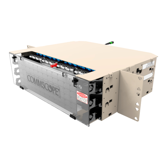
TECHNICAL ASSISTANCE ............... .54 INTRODUCTION This manual describes the 3 and 4 Rack Unit (3RU/4RU) Rapid Fiber Panel with RapidReel technology. Both models have a total capacity of 144 optical ports, and are available with singlemode RBR, multimode OM4 plenum-rated, or indoor/outdoor (I/O) cable. -
Page 3: Related Publications
The 3RU/4RU Rapid Fiber Panel is a rack-mountable fiber distribution panel that incorporates CommScope’s RapidReel fiber cable spool tray. The 3RU panel has a total capacity of 144 optical ports. The 4RU panel has a total capacity of 288 optical ports. - Page 4 ADCP-90-606 • Rev C • May 2020 26181-A FRONT VIEW REAR VIEW Figure 1. 3RU Rapid Fiber Panel REAR VIEW 26180-A FRONT VIEW Figure 2. 4RU Rapid Fiber Panel The Rapid Fiber Panel of a metal panel shell plus three or four RapidReel cable spool trays that are mounted within the panel shell.
- Page 5 A carousel for unwinding the external spools is also provided. The carousel allows the microcable on the external spools to be paid out together with the cable spool trays still mounted on the pallet. Page 5 © 2020 CommScope. All Rights Reserved.
- Page 6 26184-B CLEARANCE REQUIRED ON FRONT OR REAR OF PANEL SHELL TO FIT IN THE CABLE SPOOL TRAY REAR SIDE WHEN INSTALLING IT INSTALLATION Figure 4. RapidReel Cable Spool Tray and Panel Shell Page 6 © 2020 CommScope. All Rights Reserved.
- Page 7 In Zone 4 Earthquake applications, exceeding the weight rating can compromise the integrity of the rack during an earthquake. Page 7 © 2020 CommScope. All Rights Reserved.
-
Page 8: Basic Components
BRACKETS 26189-A GROUND CONNECTION Figure 5. Panel Shell (3RU Shown) The panel shell consists of the following components: • Enclosure – Houses RapidReel cable spool trays and protects the microcable assemblies. • Removable Front Cover – Protects the equipment patch cords at the point where they enter the panel and connect to the adapter bulkhead. -
Page 9: Rapidreel Cable Spool Tray
Distribution Frame (ODF) or fiber panel. • Spool – Stores microcable. The 3RU spool can store up to 200 feet of cable when loaded with one dual 3.0 mm plenum cable or one 12-fiber I/O cable. The 4RU spool can store up to 100 feet when loaded with one dual 3.0 mm plenum cable, one 12-fiber plenum or I/O... - Page 10 (UPC or APC), multimode SC (UPC), or multimode LC (UPC). The NG4access cabled modules will be either one 24-fiber LC module (UPC or APC) or two 12-fiber SC modules (UPC or APC). The MPO connectors are of 12-fiber construction and equipped with a Page 10 © 2020 CommScope. All Rights Reserved.
-
Page 11: Specifications And Dimensions
Each fanout assembly and NG4access cabled module is equipped with a pulling sock. Specifications and Dimensions Table 1 lists specifications the 3RU and 4RU Rapid Fiber Panel. Figure 8 shows dimensions. Table 1. Rapid Fiber Panel Specifications... -
Page 12: Accessory Kits
7.0 INCHES (17.78 CM) 4RU FRONT VIEW Figure 8. 3RU and 4RU Rapid Fiber Panel Dimensions Accessory Kits For cables equipped with 12-connector fanout assemblies, kits are available for securing the fanouts to an Optical Distribution Frame including NGF, NG3, LSX, FCM, and NG4access. A universal kit is also available for attaching 9 foot long 2 mm fanout assemblies to a Glide or interbay management panel. -
Page 13: Typical Application
2. Check the panel for damages or missing ship-along parts (per the list provided in Topic If there are damages, contact TE Connectivity for an RMA (Return Material Authorization) and to reorder if replacement is required. Page 13 © 2020 CommScope. All Rights Reserved. -
Page 14: Ship-Along Parts
Mounting the Panel on the Equipment Rack Use the following procedure to mount the panel. 1. If mounting a 3RU panel, remove the three foam shipping inserts from the rear side of the panel, as shown in Figure 10, and discard. - Page 15 11. Tighten screws to the torque specification shown in Figure 11 5. Secure the panel to the rack or cabinet using the four #12-24 screws and #12-24 lock washers provided (per local practice) as shown in Figure Page 15 © 2020 CommScope. All Rights Reserved.
- Page 16 (Isolated Bonding Network) per local practice. NOTE: FRONT GROUNDING IS NOT AVAILABLE WHEN THE MOUNTING BRACKETS ARE INSTALLED IN THE 2-INCH RECESS POSITION GROUNDING LOCATIONS REAR FRONT 26194-A Figure 13. Grounding the Rapid Fiber Panel Page 16 © 2020 CommScope. All Rights Reserved.
-
Page 17: Removing The Latch Shipping Brackets
FIBER TAPE LATCH SHIPPING LATCH BRACKET 26185-A Figure 14. Removing Fiber Tape from Latch Shipping Brackets Page 17 © 2020 CommScope. All Rights Reserved. - Page 18 ADCP-90-606 • Rev C • May 2020 2. Grab onto the latch shipping bracket and pull out the cable spool tray; then remove the blue tape. Refer to Figure BLUE TAPE LATCH SHIPPING BRACKET 26186-A Figure 15. Pulling Out Tray and Removing Blue Tape 3.
- Page 19 7. Continue down through the remaining cable spool trays, removing the blue tape and latch shipping bracket from each of the trays. Caution: When removing the latch shipping brackets, use caution to avoid damaging fibers. Page 19 © 2020 CommScope. All Rights Reserved.
-
Page 20: Unwinding Microcable From Rapidreel Cable Spool Tray
3. While holding the red latch out, push the tray back slightly. Continue pushing until the tray locks into pay out position as shown in Figure RED LATCH 25939-A Figure 20. Locking Tray Into Pay Out Position Page 20 © 2020 CommScope. All Rights Reserved. - Page 21 6. If the cable will be routed from the rear of the panel, start unwinding the internal spool by pulling on both the microcable connector pulling eye and/or cable, causing the internal spool and attached bulkhead panel to rotate. Page 21 © 2020 CommScope. All Rights Reserved.
- Page 22 ADCP-90-606 • Rev C • May 2020 Note: Provide at least 3 inches (7.6 cm) of clearance at the rear side of the panel to allow the spool to rotate freely as the microcable is unwound. Caution: Avoid using excessive force when unwinding microcable from the internal spool. Use the hand-wrap method (see Figure 22) if pulling on the cable by hand.
- Page 23 SEE DETAIL A DETAIL A #4-40 BONDING SCREW (3RU 6X, 4RU 12X) Figure 24. Location of #4-40 Bonding Screws b. Working from the rear side of the panel, press the two release tabs located on the left and right sides of the RapidReel cable spool tray as shown in Figure 25.
- Page 24 10. Using the red latch, rotate the tray clockwise and pull the tray forward to the locked operation position as shown in Figure 25919-A Figure 27. Pulling Tray Forward to Locked Operation Position Page 24 © 2020 CommScope. All Rights Reserved.
-
Page 25: Installing A Rapid Fiber Panel With External Spools
Note: The Rapid Fiber Panel is designed to be installed in an environmentally controlled network telecommunications facility such as a Central Office, Controlled Environmental Vault, or Data Center. Only the I/O cable is rated for both indoor and outdoor use. Page 25 © 2020 CommScope. All Rights Reserved. -
Page 26: Unwinding Microcable From The External Spools
Note: If the microcable will exit the panel from the rear, place the pallet at the rear side of the rack. If the microcable will exit the panel from the front, place the pallet at the front side of the rack. Page 26 © 2020 CommScope. All Rights Reserved. - Page 27 Figure 31. Removing Straps Begin unpacking the shipment container as follows, referring to Figure a. Open the top of the shipping container and remove the boxed panel shell. b. Lift off the shipping divider. Page 27 © 2020 CommScope. All Rights Reserved.
- Page 28 Figure 32. Unpacking Boxed Panel Shell and Shipping Divider 4. Lift up the shipment container and set it aside as shown in Figure 33 The external spools and RapidReel cable spool trays will remain on the pallet as shown. Page 28 © 2020 CommScope. All Rights Reserved.
- Page 29 ADCP-90-606 • Rev C • May 2020 Figure 33. Removing Shipping Container 5. Remove the spool stop/fork lift protection (Figure 34). Page 29 © 2020 CommScope. All Rights Reserved.
- Page 30 Note: Each RapidReel cable spool tray has single or dual microcables depending on configuration order. Note: A small tag is attached to each microcable near the far end connector to identify the cable number and corresponding ports on the RapidReel cable spool tray. Page 30 © 2020 CommScope. All Rights Reserved.
-
Page 31: Mounting The Panel Shell On The Equipment Rack
1.7 NM) OF TORQUE 26200-A Figure 36. Mounting Bracket Installation (3RU Panel Shell Shown) 4. If the panel is being installed in a 23-inch rack or cabinet in other than the 5-inch recess position, remove the 23-inch mounting brackets and re-install them at the required (2- or 4- inch) recess position. - Page 32 AVAILABLE WHEN THE MOUNTING BRACKETS ARE INSTALLED IN THE 2-INCH RECESS POSITION 26358-A STAR WASHERS 10-32 REAR SCREWS GROUNDING LOCATION GROUND LUG & WIRE (NOT PROVIDED) Figure 38. Grounding the Rapid Fiber Panel Chassis Page 32 © 2020 CommScope. All Rights Reserved.
-
Page 33: Mounting The Rapidreel Cable Spool Trays In The Panel Shell
1. Use a box cutter to open the box on top of the external spool as shown in Figure Figure 39. Opening Box on Top of External Spool 2. Open the box as shown in Figure Figure 40. Opening Box and Removing Tray Page 33 © 2020 CommScope. All Rights Reserved. - Page 34 (PORTS 25-48 0R 49-96) CABLE SPOOL TRAY 3 (PORTS 49-72 OR 97-144) FRONT VIEW 26203-A Figure 42. 3RU Panel Cable Spool Tray Mounting Slots and Port Designations CABLE SPOOL TRAY 1 (PORTS 1-24) CABLE SPOOL TRAY 2 (PORTS 25-48) CABLE SPOOL TRAY 3...
- Page 35 Figure 45. If the RapidReel cable spool tray will be inserted into the panel shell from the rear, proceed to step 2. Page 35 © 2020 CommScope. All Rights Reserved.
- Page 36 24-28 OR 49-96 49-72 OR 97-144 26220-A Figure 46. Aligning RapidReel Cable Spool Tray with Mounting Slot (3RU Panel Shown for Reference) 7. Press the black release tabs on both sides of the panel shell, as shown in Figure 47, and then continue sliding the cable spool tray into the mounting slot until it locks into place.
-
Page 37: Unwinding Microcable From Rapidreel Cable Spool Trays
Figure 47. Pressing Release Tabs 8. Locate #4-40 bonding screws that are sent separately with the ship-along parts (six screws for 3RU, twelve for 4RU). 9. Install the #4-40 screws on either side of the panel shell at the points indicated in Figure 48. - Page 38 Figure RED LATCH 25939-A Figure 50. Locking Tray Into Pay Out Position c. Remove blue tape that secures cable to the right rear of the panel as shown in Figure Page 38 © 2020 CommScope. All Rights Reserved.
- Page 39 40 lbs. (18.14 kg) Figure 52. Hand-Wrap Method for Pulling Cable 4. After paying out cable as required, do the following for each RapidReel cable spool tray: Page 39 © 2020 CommScope. All Rights Reserved.
- Page 40 FOR CLARITY DESIGNATION FRONT PORT CARD NOT SHOWN DESIGNATION PLATES Figure 54. Installing Front Designation Plates (3RU Panel Shown) 6. Proceed to Topic 7 on Page 41 for guidelines on routing the microcable through an trough or conduit. Page 40...
-
Page 41: Microcable Unwinding And Routing Additional Guidelines
5. Complete the following for each cable terminated with an MPO connector: a. Remove the pulling eye from each MPO connector by inserting and twisting a screwdriver or coin as shown in Figure Page 41 © 2020 CommScope. All Rights Reserved. - Page 42 6. Complete the following for each microcable terminated with a stub end non-functional connector: Note: Do not cut off the non-functional connector before cable installation has been completed or the integrity of the cable may be compromised. Page 42 © 2020 CommScope. All Rights Reserved.
- Page 43 If a pipe protection is also present (used for fanout assemblies with 900 micron fibers only), remove the pipe (refer to Figure 58). Page 43 © 2020 CommScope. All Rights Reserved.
- Page 44 If the microcable is being routed to an NG4access universal panel shell mounted on an NG4access frame, refer to the laminated cards on the rear of the frame for instructions on how to route the cable on the frame and install the cabled module. Page 44 © 2020 CommScope. All Rights Reserved.
-
Page 45: Microcable Pulled Through Conduit
40 lbs. (18.14 kg) . Use the hand-wrap method if pulling on the cable by hand. Page 45 © 2020 CommScope. All Rights Reserved. - Page 46 4. Attach a draw wire or tape to the pulling swivel and then carefully guide the pulling swivel with attached connectors into the conduit. Continue to guide the cable into the conduit while the cable is being pulled. Page 46 © 2020 CommScope. All Rights Reserved.
- Page 47 10. Complete the following for each cable terminated with an MPO connector: a. Remove the pulling eye from each MPO connector by inserting and twisting a screwdriver or coin as shown in Figure 55 on Page Page 47 © 2020 CommScope. All Rights Reserved.
- Page 48 Cut off the non-functional connector and discard. c. Determine the point at which the microcable will be attached to the splice tray and then strip back the cable jacket to expose the optical fibers. Page 48 © 2020 CommScope. All Rights Reserved.
-
Page 49: Bulkhead Adapter Access Procedure And Serial Number Locations
1. Using the red latch, carefully pull the adapter bulkhead forward until the stop position is reached. Figure 62 shows the stop position. 2. Locate the optical connector that requires cleaning and carefully disconnect it from the rear side of the bulkhead adapter. Page 49 © 2020 CommScope. All Rights Reserved. -
Page 50: Panel Shell, Rapidreel Cable Spool Tray, And Microcable Labels
In addition, a serial number label is attached to both the RapidReel cable spool tray and the microcables. The locations of the various labels are shown in Figure Figure 64 shows the serial number system used. Page 50 © 2020 CommScope. All Rights Reserved. - Page 51 MPO 97-108 3 RAPIDREEL CABLE MPO 108-120 SPOOL TRAYS PER PANEL S/N-3 SPOOL (4 MPOs PER TRAY) MPO 121-132 MPO 133-144 26222-A Figure 64. Serial Numbering for 3RU Panel With External Spool Page 51 © 2020 CommScope. All Rights Reserved.
-
Page 52: Operation
4. Insert the patch cord connector into the appropriate bulkhead adapter and record the connection on the designation card attached to the front cover. 5. Repeat steps 2 through 5 for any remaining connections that may be required. Page 52 © 2020 CommScope. All Rights Reserved. -
Page 53: Rapidreel Cable Spool Tray Positions And How To Use Them
(outward). The panel ships in the operation position with the spool locking tab protruding through the right side of the panel shell as shown in Figure SPOOL LOCKING LATCH 26178-A Figure 67. Operation (Home) Position (Panel Shown With Top Cover Cut Away) Page 53 © 2020 CommScope. All Rights Reserved. -
Page 54: Technical Assistance
10 TECHNICAL ASSISTANCE ® To find out more about CommScope products, visit us on the web at www.commscope.com For technical assistance, customer service, or to report any missing/damaged parts, visit us at http://www.commscope.com/SupportCenter...
Need help?
Do you have a question about the 3RU and is the answer not in the manual?
Questions and answers