Table of Contents
Advertisement
Advertisement
Table of Contents

Subscribe to Our Youtube Channel
Related Manuals for CommScope ION-M80


Summary of Contents for CommScope ION-M80
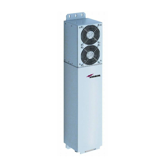
- Page 1 Optical Remote Unit ION™- M80/90/19P (M-Cabinet) User's Manual MF0133ABA...
- Page 2 ION™-M80/90/19P © Copyright 2011 CommScope, Inc. All rights reserved. Andrew Solutions is a trademark of CommScope, Inc. All information contained in this manual has been revised thoroughly. Yet Andrew Solutions accepts no liability for any omissions or faults. Andrew Solutions reserves the right to change all hard- and software characteristics without notice.
-
Page 3: Table Of Contents
HEALTH AND SAFETY WARNINGS 1.3. ABOUT ANDREW SOLUTIONS 1.4. INTERNATIONAL CONTACT ADDRESSES FOR CUSTOMER SUPPORT 2. FUNCTIONAL DESCRIPTION 2.1. PURPOSE 2.2. THE ION-M80/90/19P 2.3. COMPONENTS OF THE ION-M80/90/19P REMOTE UNIT 2.3.1. Fan-Protection Kit 2.3.2. Accessories 3. COMMISSIONING 3.1. MECHANICAL INSTALLATION 3.1.1. General 3.1.2. - Page 4 3-3 Pole mounting (metric dimensions) ............17 figure 3-4 Mounting procedure for fan protection (metric dimensions)...... 18 figure 3-5 Connector flange of ION-M80/90/19P ............20 figure 3-6 Grounding bolt with loosened hex nut ............21 figure 3-7 Grounding bolt, schematic view..............21 figure 3-8 AC mains plug ..................
-
Page 5: General
1 General 1. GENERAL 1.1. USED ABBREVIATIONS 3GPP Generation Partnership Project AC/DC Alternating current / Direct Current AIMOS Andrew Integrated Management and Operating System Automatic Level Control BITE Built-In Test Equipment Base Transceiver Station "Conformité Européenne" ("European Conformity") Compact Disk Channel Power Detection Downlink Declaration of Conformity... -
Page 6: Health And Safety Warnings
User’s Manual for Remote Unit ION™-M80/90/19P 1.2. HEALTH AND SAFETY WARNINGS 1. Only suitably qualified personnel is allowed to work on this unit and only after becoming familiar with all safety notices, installation, operation and maintenance procedures contained in this manual. 2. - Page 7 1 General 12. Before opening the unit, disconnect mains. 13. ESD precautions must be observed! Before commencing maintenance work, use the available grounding system to connect ESD protection measures. 14. This unit complies with European standard EN60950. 15. Make sure the repeater settings are according to the intended use (see also product information of manufacturer) and regulatory requirements are met.
-
Page 8: About Andrew Solutions
Andrew Wireless Systems GmbH has unparalleled experience in providing RF coverage and capacity solution for wireless networks in both indoor and outdoor environment and belongs to Andrew Solutions, a CommScope Company. Andrew Solutions is the foremost supplier of one-stop, end-to-end radio frequency (RF) solutions. -
Page 9: International Contact Addresses For Customer Support
1 General 1.4. INTERNATIONAL CONTACT ADDRESSES FOR CUSTOMER SUPPORT Americas: Canada United States Andrew Solutions, Andrew Solutions Canada Andrew LLC, A CommScope Company 620 North Greenfield Parkway 620 North Greenfield Parkway Mail Garner, NC 27529 Mail Garner, NC 27529 U.S.A. - Page 10 +41-62-386-1261 E-mail WIsupport.austria@commscope.com E-mail WIsupport.ch@commscope.com Italy Spain and Portugal Andrew Solutions España S.A. Commscope Italy S.r.l., Faenza, Italy A Commscope Company Avda. de Europa, 4 - 2ª pta. Via Mengolina, 20 Parque Empresarial La Moraleja Mail 48018 Faenza (RA) Mail...
-
Page 11: Functional Description
The unit also provides a transparent link in the frequency range from 2496 MHz to 2690 MHz, which can be used e.g. for WiMAX applications in this frequency range. The Remote Unit ION-M80/90/19P (Intelligent Optical Network; MMR) is connected to a central Master Unit via optical-fibre lines. -
Page 12: Components Of The Ion-M80/90/19P Remote Unit
User’s Manual for Remote Unit ION™-M80/90/19P 2.3. COMPONENTS OF THE ION-M80/90/19P REMOTE UNIT 2.3.1. Fan-Protection Kit In order to protect the fan unit (e.g. against rain), a protective cover to be mounted over the air inlet is delivered with the unit. For more details see chapter 3.1.4 Mounting of Fan Protection. -
Page 13: Commissioning
3 Commissioning 3. COMMISSIONING 3.1. MECHANICAL INSTALLATION 3.1.1. General Read the health and safety warnings in chapter 1.2. 1. Do not install the unit in a way or at a place where the specifications outlined in the Environmental and Safety Specifications leaflet of the supplier are not met. - Page 14 User’s Manual for Remote Unit ION™-M80/90/19P 7. A spacing of 40 mm (1.58 inch) around the unit is required. 8. To ensure sufficient airflow when mounting the unit in enclosed spaces, two lid openings (one for the air inlet and the other for the air outlet) have to be provided.
-
Page 15: Wall-Mounting Procedure
3 Commissioning 3.1.2. Wall-Mounting Procedure Check the suitability of the wall-mounting kit and the wall. Mark the position of the drilling holes (for measurements refer to figure 3-1 Wall mounting). Drill four holes at the marked positions and insert dowels *. Use a cap nut or lock nut to screw the four dowel screws into the dowels and put the distance tubes... -
Page 16: Pole-Mounting Procedure
User’s Manual for Remote Unit ION™-M80/90/19P 3.1.3. Pole-Mounting Procedure Standard mounting hardware cannot be used to mount the Remote Unit to a pole, a column or other similar structures. Additional hardware must be used for this type of installation. Such a pole-mounting kit could include two threaded rods M8, two U-beams and mounting material like bolts and nuts. -
Page 17: Figure 3-3 Pole Mounting (Metric Dimensions)
3 Commissioning Lock washer for M8.0 DIN 127 Washer DIN 125 Lock for folding A2 Form B Optical TESPA screw band, Form B Ø 8.0 screw band ES 119 Remote Unit stainless, 11 mm Hexagon nut M8 DIN 934 Pole Pole Pole-mounting bracket... -
Page 18: Mounting Of Fan Protection
User’s Manual for Remote Unit ION™-M80/90/19P 3.1.4. Mounting of Fan Protection Since the fan protection is required for the outdoor usage of a stand-alone Remote Unit, the mounting of this optional equipment is also described in this manual. To install the protective cover of the fan protection kit, first unscrew the four screws with the respective lock washers from the cover of the air inlet of the Remote Unit, and instead, screw in the four spacing bolts M4.0x30 with the four lock washers M4.0 DIN125 that are part of the fan protection kit. -
Page 19: Electrical Installation
3 Commissioning 3.2. ELECTRICAL INSTALLATION 3.2.1. General Read the health and safety warnings in chapter 1.2. 1. This unit contains dangerous voltages. Loss of life, severe personal injury or property damage can be the result if the instructions contained in this manual are not followed. -
Page 20: Connections
13. Observe the labels on the front panels before connecting or disconnecting any cables. 3.2.2. Connections N-connector Mobile Connector Status External Alarm output 800 MHz & 900 MHz to EU alarm input Mains Grounding N-connector Mobile Optical-fibre connector bolt 1900 MHz connector figure 3-5 Connector flange of ION-M80/90/19P Page 20 MF0133ABA.doc... -
Page 21: Grounding
3 Commissioning 3.2.3. Grounding Grounding must be carried out. Connect an earth-bonding cable to the grounding connection provided at the outside of the Remote Unit (see chapter 3.2.2 Connections). Do not use the grounding connection to connect external devices. figure 3-6 Grounding bolt with figure 3-7 Grounding bolt, schematic view loosened hex nut After loosening the hex nut, connect the earth-bonding cable between the two... -
Page 22: Power Connection
User’s Manual for Remote Unit ION™-M80/90/19P 3.2.4. Power Connection Before connecting electrical power to the units, the system must be grounded as described in the previous chapter. Mains power must be connected at the mains connector of the unit (see chapter 3.2.2 Connections). -
Page 23: Connection Of The Antenna Cables
3 Commissioning 3.3. CONNECTION OF THE ANTENNA CABLES The Remote Unit has N-type antenna connectors. For its location please refer to chapter 3.2.2 Connections. For mounting the cable connectors, it is recommended to refer to the corresponding documentation of the connector manufacturer. The bending radius of the antenna cables must remain within the given specifications. - Page 24 User’s Manual for Remote Unit ION™-M80/90/19P System attenuation and attenuation of optical components must be determined. This can be achieved by measuring attenuation and reflection with an appropriate measuring instrument. For pigtails, a total value of < 0.4 dB (measured to a reference plug) can be assumed due to the dead zone of the reflectometer.
- Page 25 3 Commissioning Cleaning Procedure for Fiber-Optical Components: Any contamination in the fiber connection results in additional optical transmission loss which could cause whole system failure. It is thus recommended that every fiber connector be inspected and cleaned prior to mating. The goal is to eliminate any dust or contamination and to provide a clean environment for the fiber-optic connection.
-
Page 26: Protective Plug
User’s Manual for Remote Unit ION™-M80/90/19P 3.4.1. Protective Plug Connection: A protective plug is provided for the connection of the fibre-optic cables. figure 3-10 Protective-plug assembly Note: Only high-quality connectors must be used for this type of plug. Qualified brands are Diamond or Huber & Suhner. Page 26 MF0133ABA.doc... - Page 27 3 Commissioning For plug assembly, observe the following instruction: 1. Pass one or two contacts through the backshell and the clamp ring. 2. Place the contact(s) on the lower insulation body by pushing the groove of the contact into the cavity. If there is only one contact, cavity A must be used. * 3.
-
Page 28: Protective-Tube Kit
User’s Manual for Remote Unit ION™-M80/90/19P 7. Bring the plastic ring over the cable(s), push it into the backshell and compress the seals and plastic ring by screwing the clamp ring tight (no gap) using a spanner with opening 20. *** Screw tight until gap is closed 8. -
Page 29: Figure 3-11 Tube-Kit Installation
3 Commissioning Protective plug Fiber cable Ring 3/4 Screw the reducer to the protective plug Reducer backshell without any gap! Coupling Place the appropriate seal parts (with) one groove for one contact or two grooves for two contacts) over the cable(s) and push them into Protective tube the backshell! -
Page 30: Commissioning
User’s Manual for Remote Unit ION™-M80/90/19P 3.5. COMMISSIONING Read the health and safety warnings in chapter 1.2 as well as the description carefully to avoid mistakes and proceed step by step as described! Do not operate the Remote Unit without terminating the antenna connectors. The antenna connectors may be terminated by connecting them to their respective antennas or to a dummy load. - Page 31 3 Commissioning Commissioning an ION-M Remote Unit Manual for Remote Start Unit Philips Preperation screwdriver Unpack RU, RU accessories and mounting kit. Mounting kit Spanner, size 13 mm Drilling Mechanical installation machine Fasten wall or pole mounting kit to wall or Dowels pole.
- Page 32 User’s Manual for Remote Unit ION™-M80/90/19P LED on? Check power switch inside RU (RUs with door). Check mains cabling. Check mains power. LED status Internal Error Change power supply (RUs with a door) Reduce environmental temperature. Eliminate thermal short circuit. Disconnect and connect mains.
-
Page 33: Alarms
4 Alarms 4. ALARMS 4.1. BITE AND ALARMS The Built-In Test concept comprises the monitoring of the power supplies, the power amplifiers and the optical interface. All occurring alarms can be checked via software at the Master Unit. 4.2. HANDLING OF ALARMS As soon as the software acknowledges a valid alarm, a message is transmitted to the Master Unit. - Page 34 User’s Manual for Remote Unit ION™-M80/90/19P Alarms directly related to RU: Change power supply (RUs with door). Power 28 V Replace the affected remote unit. Reduce environmental temperature. Temperature Eliminate thermal short circuit. Disconnect and connect mains. Fans should run. If not, replace the fans at I²C Disconnect and connect mains.
-
Page 35: External Alarm Inputs And Outputs
4 Alarms 4.5. EXTERNAL ALARM INPUTS AND OUTPUTS G1038Z0 G1038Z0 figure 4-1 Flange connector, 5 poles figure 4-2 Flange connector, 7 poles The alarm outputs (open collector output 5 V / 1 mA) are normally low. In case of an alarm they are high active (5 V). -
Page 36: Troubleshooting
User’s Manual for Remote Unit ION™-M80/90/19P With the external alarm inputs it is possible to monitor the status of connected devices, e.g. a UPS, via software. All alarm inputs are normally high (5 V) without connection. The polarity (high/ low) can be set via the software at the Master Unit (for details please see according software manual). - Page 37 These cleaning intervals depend mainly on the location of the Remote Unit and the corresponding degree of pollution. Maintenance of the ION-M80/90/19P should be performed by replacing only components that are contained in this chapter. In order to maintain warranty, take care not to damage unintentionally the seals on the modules.
- Page 38 User’s Manual for Remote Unit ION™-M80/90/19P 5.2. REPLACING THE FAN UNIT Replacement of the fan unit is not required as a preventative measure. Only if an alarm indicates a malfunctioning of a fan must the unit be exchanged. Note: Please observe that the fan unit can only be replaced as a whole. Do not remove the fans separately.
- Page 39 5 Maintenance 5. To mount the new fan unit, re-connect the earth-bonding cable and the fan connector (see step 4). Then, place the fan unit back into its original position and fasten it tight as shown below: 6. Screw the whole fan unit to the cabinet with the four tallow-drop screws M4x8 (see step 2).
- Page 40 User’s Manual for Remote Unit ION™-M80/90/19P 5.3. CLEANING THE HEAT SINK Note: Read the health and safety warnings in chapter 1.2 as well as the instructions in chapter 5.1 General before starting with the replacement procedure. Then, proceed as follows: 7.
-
Page 41: Figure 6-1 Installation Drawing
6 Appendix 6. APPENDIX 6.1. ILLUSTRATIONS figure 6-1 Installation drawing Page 41... - Page 42 User’s Manual for Remote Unit ION™-M80/90/19P 6.2. SPECIFICATIONS 6.2.1. Electrical Specifications ION-M80/90/19P Electrical Power Mains power 115 Vac or 230 Vac supply Power consumption 530 Watts Optical Connectors E2000/APC 8° Optical return loss 45 dB minimum Fiber type Single mode E9/125 mm...
- Page 43 Maintenance of the ION-M80/90/19P should be performed on an FRU (Field Replaceable Unit) basis only. Do not damage the warranty labels on the components, as this voids the warranty.
- Page 44 User’s Manual for Remote Unit ION™-M80/90/19P 7. INDEX Address of Andrew Wireless Systems GmbH..10 Illustrations ............41 Alarms Installation Alarm Status ............ 33 Electrical ............19 Bite and Alarms ..........33 Mechanical ............13 External Inputs........... 35, 36 Handling of Alarms .......... 33 List ..............
Need help?
Do you have a question about the ION-M80 and is the answer not in the manual?
Questions and answers