Chapters
Table of Contents

Related Manuals for Wamsler W1-75


Summary of Contents for Wamsler W1-75
- Page 1 Aufstell- und Bedienungsanleitung Instructions for Installation and Use Instructions de montage et d’utilisation Istruzioni per l’installazione e l’uso Kezelési és használati útmutató W1-75...
-
Page 2: Vorwort
Vorwort Sehr verehrter Kunde, wir beglückwünschen Sie zum Erwerb unseres Festbrennstoffherdes. Sie haben die richti- ge Wahl getroffen. Denn mit diesem Produkte haben Sie die Garantie für Hohe Qualität durch Verwendung bester und bewährter Materialien • Funktionssicherheit durch ausgereifte Technik, die streng nach deutschen bzw. •... -
Page 3: Table Of Contents
Inhaltsverzeichnis Vorwort ..........................2 Inhaltsverzeichnis ......................... 3 1. Installation ........................4 Sicherheitshinweise ..................... 4 Geräteaufbau....................... 6 Vorschriften ......................7 Aufstellraum......................7 Verbrennungsluft ....................7 Elektro-Anschluss ....................8 Sicherheitsabstände .................... 8 Schornsteinanschluss ..................9 Wahl der Abgasanschlussrichtung ..............10 1.9.1 Obenanschluss (Bild 1) ................10 1.9.2 Seitenanschluss (Bild 1) ................. -
Page 4: Installation
Installation Sicherheitshinweise Die Geräte sind nach DIN EN 12815 geprüft (Typenschild). Für die Aufstellung und den abgasseitigen Anschluss sind die Forderungen der Feuerungsverordnung (FeuVO), die jeweiligen Länderbauordnungen sowie die DIN 4705, DIN EN 13384, DIN 18160, DIN 18896, DIN EN 1856-2 und der DIN EN 15287 zu beachten. - Page 5 Wenn Ausbesserungen oder Erneuerungen vorgenommen werden müssen, wen- den Sie sich bitte rechtzeitig unter Angabe der genauen Artikel-Nr. und Ferti- gungs-Nr. an Ihren Fachhändler. Es sind nur Original WAMSLER - Ersatzteile zu verwenden. Arbeiten, wie insbesondere Installation, Montage, Erstinbetriebnahme und Ser- vicearbeiten sowie Reparaturen, dürfen nur durch einen ausgebildeten Fachbe-...
-
Page 6: Geräteaufbau
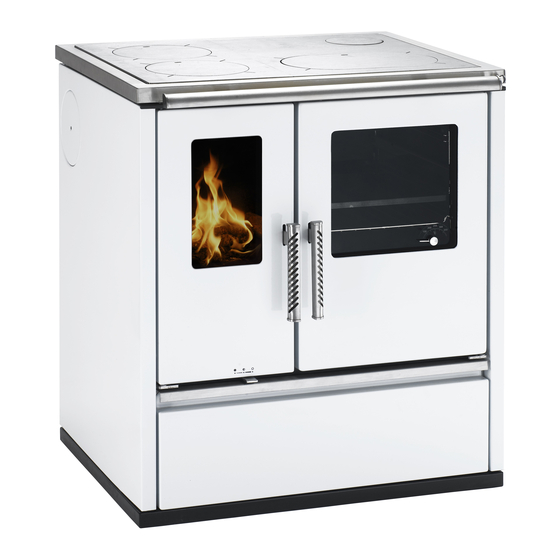
Geräteaufbau W1-75 Legende: Serienzubehör: Primärluftregler - Backblech Stahlplatte - Bratrost Abgasanschlüsse - Deckelheber Anheizklappe - Russkratzer Schamotteverkleidung im Feuerraum - Schürhacken Rost - Schutzhandschuh Holzfang (Reling) - Rauchlochdeckel Seitenwand Aschekasten Sonderzubehör: 10. Sekundärluftregler - ISO Panel 11. Brennstoffwagen - Fettpfanne 12. -
Page 7: Vorschriften
Vorschriften Für die Aufstellung und den abgasseitigen Anschluss sind die Forderungen der Feue- rungsverordnung (FeuVO), die jeweiligen Länderbauverordnungen sowie DIN 4705, DIN EN 13384, DIN 18160, DIN 18896, DIN EN 1856-2 und DIN EN 15287 zu beachten. Zur korrekten Funktion Ihres Gerätes muss der Schornstein, an den Sie das Gerät an- schließen wollen, in einwandfreiem Zustand und mind. -
Page 8: Elektro-Anschluss
Wichtige HINWEISE zum Thema raumluftabhängiger oder raumluftunabhängiger Betrieb (gültig für Deutschland - Stand Januar 2014): Die Herde sind als raumluftabhängige Herde nach DIN EN 12815 geprüft. Die Herde • entnehmen die gesamte Verbrennungsluft über den zentralen Luftansaugstutzen aus dem Aufstellraum. An diesem Stutzen kann bauseits eine dichte Luftzuführung ange- schlossen werden. -
Page 9: Sicherheitsabstände
Werk gelieferten 50mm Abstandsverbindung bei Einbau (Zwischenbauteil) bis auf „0“ reduziert werden. Die 50mm Abstandsverbindung wurde speziell für die Herde W1-75 sowie W1-40 entwickelt und typgeprüft. Eventuell über dem Gerät angebrachte brennbare Gegenstände sind in angemessener Entfernung zu halten. Der Mindestabstand beträgt 700 mm. -
Page 10: Schornsteinanschluss
Schornsteinanschluss Der für den Anschluss vorgesehene Schornstein muss bis mind. 400° C belastbar sein. ACHTUNG: Vor dem Anschluss des Gerätes ist in jedem Fall der zuständige Bezirks- Schornsteinfegermeister zu Rate zu ziehen! Verbindungsstücke müssen am Gerät und untereinander fest und dicht verbunden sein. Sie dürfen nicht in den freien Schornsteinquerschnitt hineinragen. -
Page 11: Seitenanschluss (Bild 1)
1.9.2 Seitenanschluss (Bild 1) hinteren Abgasstutzen (1) durch Lockern der Schrauben entfernen • Seitenverkleidungsdeckel (10) durch Lockern der Schraube entfernen • Die Schrauben vom Blinddeckel (12) seitlich lockern und Deckel entfernen • Abgasstutzen (1) an der Seitenwand fest verschrauben • Abgasanschluss hinten mit entfernten Blinddeckel (12) von außen verschließen und •... - Page 12 Richtig Falsch Richtig Falsch min. 50 cm mind. 50 cm Querschnittsverengung im Kamin durch zu weit eingeschobene Querschnittverengung im Kamin durch zu Abgasrohre weit eingeschobene Abgasrohre Stau durch sich gegenseitig behindernde Stau durch sich ge- mind. 30 cm min. 30 cm genseitig behin- Abgasströme...
-
Page 13: Brennstoffe / Einstellungen
Stunde auf max. Nennwärmeleistung heizen. Sollte beim ersten Heizvorgang die max. Temperatur nicht erreicht werden, können die Geruchsbeläs- tigungen auch später nochmals auftreten. Maximale Aufgabemengen pro Brennstofffüllung W1-75 6,2 kg (6 - 7 Briketts) bei Nennwärmeleistung Braunkohlebriketts 6,2 kg (6 - 7 Briketts) bei Dauerbrand... -
Page 14: Verbrennungslufteinstellung
Verbrennungslufteinstellung Die Tabelle zeigt die erforderlichen Einstellungen nach Betriebsart und Brennstoff. Primärluft- Anheizklappe- Sekundärluft- Brenndauer Brennstoff Stellung Stellung Stellung in h Anheizen Scheitholz ca. 1 Braunkohlebriketts NWL ca. 3 Braunkohlebriketts Dauerbrand ca. 12 Außerbetriebnahme: Keinen Brennstoff mehr nachlegen oder Tabelle 2 Bedienung Bedienungselemente und Einstellungen 3.1.1... -
Page 15: Anheizklappe
3.1.3 Anheizklappe Zum Anzünden muss die Anheizklappe geöffnet und zum Kochen und Heizen geschlossen sein. 1 - Geschlossen (Kochen, Backen, Braten, Heizen) 2 - Offen (anzünden) ACHTUNG Eine offen stehende Anheizklappe während des Heizbetriebes führt zur Überhitzung des Herdes und damit zur Beschädigung von Herdteilen. Außerdem hat eine geöff- nete Anheizklappe einen erhöhten Brennstoffverbrauch zur Folge. -
Page 16: Anzünden
Anzünden Die Leistungsregulierung wird unter Beachtung der Brennstoffart je nach Zugstärke und gewünschter Heizleistung eingestellt. Mit Scheitholz insbesondere mit Weichholz, ist nur ein eingeschränkter Brand möglich. Braunkohlebriketts sind für den Dauerbrand über Nacht besonders geeignet, wenn sie auf eine satte Grundglut aufgelegt werden. Erstes Anheizen / Betrieb Vor Inbetriebnahme sind die evtl. -
Page 17: Braten Und Backen Im Bratrohr
Braten und Backen im Bratrohr Der Herd ist mit einem Bratrohr aus Edelstahl mit Teleskopauszügen ausgestattet. Das Bratrohr hat eine Türe mit Glas, auf der ein Thermometer angebracht ist. Die angezeigte Temperatur dient nur als Anhaltspunkt beim Backen und Braten. Außerdem ist das Bratrohr serienmäßig mit einem Rost und einem Backblech ausgerüstet. -
Page 18: Pflege Und Reinigung
Pflege und Reinigung 3.7.1 Gerät (Bild 4) Nach Öffnen der Heiztür ist der Rost vor jeder Brennstoffaufgabe mit Hilfe des Russkrat- zers und des Schürhakens zu reinigen. Der Aschebehälter (1) ist täglich zu entleeren. Mindestens jeden dritten Tag sollte die Schlacke vom Rost entfernt werden. -
Page 19: Auswechseln Der Glühbirne
Dehnfugen der Stahlherdplatte müssen stets frei von Verkrustungen sein, um ein Verfor- men der Stahlherdplatte und der Seitenverkleidungen zu vermeiden. Wenn notwendig, sollte auch der Anschlag der Deckel von eventuellen Ablagerungen befreit werden. 3.7.5 Auswechseln der Glühbirne Die Glühbirne im Backofen ist hohen Temperaturen ausgesetzt. Obwohl es sich dabei um eine Spezial-Glühbirne handelt, kann sie dennoch im Laufe der Zeit durchbrennen. -
Page 20: Störungsursachen Und Behebung
Störungsursachen und Behebung Ihr Herd ist nach den neuesten technischen Erkenntnissen gebaut. Dennoch können Störungen auftreten, die ihre Ursache im Schornstein, im Brennstoff oder im Abgasrohrsystem haben. Eine kurzzeitige Geruchs- und Rauchentwicklung bei der ersten Inbetriebnahme ist normal. Auf eine ausreichende Belüftung des Raumes ist zu achten. -
Page 21: Technische Daten
1161 / 812mg/Nm Wirkungsgrad 75,6 / 76,4% Netzspannung 230 V AC Glühbirne 15 W Maßzeichnung W1-75 850 (+20) 692 (+20) 900 (+20) 742 (+20) Stellfüße herausschrauben, Herdhöhe von +20 mm möglich Die angeführten Abmessungsangaben sind nur zur Information! Wir behalten uns das Recht von Konstruktionsänderungen vor, falls diese das technische Niveau... -
Page 22: Garantiebedingungen
Wir übernehmen Garantieverpflichtungen nur für solche Geräte, die nachweislich von einem zugelassenen Installateur bzw. anerkannten Fachmann angeschlossen und einre- guliert worden sind. Mängelrüge: Beanstandungen an der gelieferten Ware wegen offensichtlicher Mängel haben spätestens innerhalb von 14 Tagen nach Empfang der Ware schriftlich zu erfolgen. Soweit bis jetzt verarbeitetes Rohmaterial nicht mehr zu beschaffen ist, sind wir berechtigt, Austauschstof- fe zu verwenden. -
Page 23: Garantiekarte
Transportschäden werden nur dann anerkannt und beseitigt, wenn eine Schadensaufnah- me des Spediteurs oder eine bahnamtliche Bescheinigung vorliegt, oder wenn unverzüg- lich glaubhaft nachgewiesen wird, dass die Verursachung bei WAMSLER liegt. Auch nach Beendigung der Garantiezeit steht Ihnen unsere Kundendienstorganisation auf Wunsch gerne zur Verfügung. - Page 24 Wamsler Haus- und Küchentechnik GmbH • Adalperostraße 86 • D-85737 Ismaning • Tel. +49 (0)89 / 320 84-0 • Fax +49 (0)89 / 320 84-238 info@wamsler.eu • www.wamsler.eu © Wamsler Haus- und Küchentechnik GmbH, 85737 Ismaning. Alle Rechte und Änderungen vorbehalten.
- Page 27 Instructions for Installation and Use Solid Fuel Cooker W1-75...
-
Page 28: Preface
Preface Dear Customer, Congratulations on your purchase of our solid fuel stove. You have made a good choice. Because this product guarantees you: High Quality thanks to use of top quality, proven materials • Safe Running thanks to mature technology which has been tested for strict ad- •... -
Page 29: Table Of Contents
Table of Contents Preface ..........................28 Table of Contents ....................... 29 Installation ......................30 Safety measures ....................30 Parts ........................32 Instructions ......................33 Surrounding space .................... 33 Air supply ......................33 Electrical connections ..................34 Safe distances ....................35 Chimney attachment .................. -
Page 30: Installation
Installation Safety measures The stoves are tested to EN 12815 (see identification plate). For installation and for flue gas connections, the requirements of the Fire Regula- tions (FeuVO in Germany) apply, as well as local building regulations such as the following technical standards DIN 4705, EN 13384, DIN 18160, DIN 18896, EN 1856-2 and EN 15287. - Page 31 18. If repairs or replacements are necessary, please contact your supplier with the necessary article numbers and serial numbers in good time. Only original WAMSLER replacement parts may be used. 19. Work such as installation, setup, commissioning and services, as well as repairs, must only be carried out by qualified personnel (heating system or space heating technicians).
-
Page 32: Parts
Parts W1-75 Key: Standard accessories: 1. Primary air control - Baking tray 2. Steel plate - Roasting grill 3. Flue gas connections - Lever to lift covers 4. Start damper - Soot scraper 5. Refractory clay layer in fire chamber - Fire iron 6. -
Page 33: Instructions
Instructions For installation and for connection of flue, the requirements of the Fire Regulations (FeuVO in Germany) apply, as well as local building regulations such as the following technical standards DIN 4705, EN 13384, DIN 18160, DIN 18896, EN 1856-2 and EN 15287. In order for the stove to function correctly the chimney to which you want to connect the stove must be in good condition. -
Page 34: Electrical Connections
Important NOTES relevant to operation dependent on air supply from room or inde- pendent of air supply from room (valid for Germany – as of January 2005): The stoves have been tested under EN 12815 as stoves relying on air supply from •... -
Page 35: Safe Distances
Safe distances The following distances must be respected as safety margins from flammable objects and bearing walls made of reinforced concrete and partition walls made from flammable mate- rials or covered in flammable materials: Beneath the hob plate (from the top of the stove to the floor) A ≥... -
Page 36: Choice Of Flue Gas Connection Placement
angle of 10 degrees. Any pipes which are not heat insulated or verti- cal must not be longer than 1 metre. The requirements of the Fire Regulations (FeuVO) apply, as well as local building regulations such as for the chimney standards DIN 4705, EN 13384, DIN 18160 and EN 15287. -
Page 37: Electrical Circuit Diagram
Fig. 3 1.9.3 Electrical circuit diagram The stove may only be connected by a qualified professional electrician according to cur- rent rules and regulations. Mains current AC 230 V Rocker switch Light Terminal strip Fig. 4 Stove frame Retaining plate... - Page 38 Wrong Right min. 50 cm Chimney diameter reduced due to flue being inserted too far into chimney Blockage due to exhaust gases interfering with each other min. 30 cm Air leak due to ppen doors on stove which is not in use Air leak from open pipe connection Air leak from...
-
Page 39: Fuels / Settings
Maximum fuel quantities per load W1-75 6,2 kg (7 - 8 briquettes) at nominal heat load Lignite briquettes... -
Page 40: Combustion Airflow Settings
Combustion airflow settings The settings must always be as shown. Primary Secondary air- Combus- Start damper Fuel airflow set- flow setting tion dura- setting ting tion in hrs Lighting Nominal heat Firewood approx. 1 load Nominal heat Lignite briquettes approx. 3 load Long-term Lignite briquettes... -
Page 41: Start Damper
3.1.3 Start damper For lighting the stove the start damper must be open and when cooking or heating it must be closed. Closed (cooking, baking, roasting, heating) Open PLEASE NOTE Leaving the start damper open when heating will cause the stove to overheat which will damage the stove and its parts. -
Page 42: Lighting
Lighting The performance control is set depending on the type of fuel as a function of the chimney draught and the desired heating level. With firewood and particularly with softwood, only a limited heating period is possible. Lignite briquettes are much better suited to burning overnight, if they are placed on top of a layer of glowing embers. -
Page 43: Closing Down
Please observe the following NOTES: Check that the start damper has been shut for at least 60 minutes. This ensures an even temperature throughout the oven. Only put in enough fuel to reach the desired tempera- ture. This temperature can then be maintained by adding small amounts of fuel during the roasting period. -
Page 44: Varnished And Enamel Surfaces
After finishing cleaning, the heating and hob plates must be replaced correctly. The clean- ing cover (4) under the oven needs to be closed tightly again. PLEASE NOTE: After every period of heating you should check the stove thoroughly. If repairs or replacements are necessary, please contact your supplier with the necessary article numbers and serial number in good time. - Page 45 PLEASE NOTE: Before opening the bulb protector, disconnect the stove from the mains! Work such as installation, setup, commissioning and servicing, as well as repairs, must only be carried out by qualified personnel (heating system or space heating technicians). Intervention by non-qualified persons invalidates the warranty and guarantee.
-
Page 46: Troubleshooting
Troubleshooting Your stove has been built using modern technology. Even so, problems can arise, which may derive from the chimney, the fuel or the flue pipe system. There may briefly be smoke and an unpleasant smell the first time you use the stove: this is normal. -
Page 47: Technical Data
1161 / 812mg/Nm Efficiency 75,6 / 76,4% Mains current 230 V AC Bulb 15 W Dimensions W1-75 850 (+20) 692 (+20) 900 (+20) 742 (+20) screw feet can raise stove height by +20 mm Weight: Net 171 kg The dimension shown is only for information! We reserve the right to make changes to the... -
Page 48: Guarantee Conditions
We will only provide a guarantee for equipment which can be shown to have been con- nected and set up by an approved installer or another recognised professional. Complaints: Complaints about delivered goods relating to obvious faults must be made in writing within 14 days of receipt. -
Page 49: Guarantee Card
Damage in transit can only be accepted and corrected, if a damage report is presented from the transporter or a railway official, or if it is proved credibly and without any delay that the cause lies with WAMSLER. Our customer service department is also available and happy to assist you on request after the end of the guarantee period. - Page 50 Wamsler Haus- und Küchentechnik GmbH • Adalperostraße 86 • D-85737 Ismaning • Tel. +49 (0)89 / 320 84-0 • Fax +49 (0)89 / 320 84-238 info@wamsler.eu • www.wamsler.eu © Wamsler Haus- und Küchentechnik GmbH, 85737 Ismaning. Alle Rechte und Änderungen vorbehalten.
- Page 51 Instructions de montage et d’utilisation Cuisinière à combustibles solides W1-75...
-
Page 52: Préface
Préface Cher client, Nous vous félicitons d’avoir fait l’acquisition de notre cuisinière à combustible solide. Vous avez fait le bon choix. Ce produit vous donne en effet la garantie d’une qualité élevée obtenue grâce à l’utilisation des matériaux les meilleurs et •... - Page 53 Sommaire Préface ..........................52 Installation ......................54 Consignes de sécurité ................. 54 Structure de l’appareil .................. 56 Règlements ....................57 Pièce d’emplacement ................... 57 Air de combustion ..................57 Raccordements électriques................58 Distances de sécurité ................... 59 Raccordement à la cheminée ..............59 Choix de la direction de l’évacuation des fumées ........
-
Page 54: Installation
Installation Consignes de sécurité Les appareils ont été contrôlés selon les normes EN 12815 (Plaque signalétique). Pour la mise en place des appareils et le raccordement aux cheminées d’évacuation des gaz, on devra observer les exigences énoncées par les directives concernant les appareils de chauffage (FeuFO en Allemagne) ainsi que les normes DIN 4705, EN 13384, DIN 18160, DIN 18896, EN 1856-2 et EN 15287. - Page 55 à votre commerçant spécialisé en lui indiquant exactement le numéro de référence et le numéro de fabrication. On ne peut utiliser que des pièces originales WAMSLER. Les travaux, tels que, en particulier, l’installation, le montage, la première mise en service, les travaux de maintenance ainsi que les réparations ne pourront être effectués que par une...
-
Page 56: Structure De L'appareil
Structure de l’appareil W1-75 Légende : Accessoires de série : 1. Réglage de l’air primaire - Plaque de four 2. Plaque d’acier - Gril 3. Raccordement pour les gaz d’évacuation - Levier de couvercle 4. Volet d’allumage - Brosse à suie 5. -
Page 57: Règlements
Règlements Pour la mise en place des appareils et le raccordement aux cheminées d’évacuation des gaz on devra observer les exigences des pays et des régions énoncées par les directives concernant les appareils de chauffage (FeuVO en Allemagne) ainsi que les normes DIN 4705, EN 13384, DIN 18160, DIN 18896, EN 1856-2 et EN 15287. - Page 58 Consignes importantes concernant le fonctionnement d’appareils dépendants ou indépendants de l’air ambiant (valable pour l'Allemagne – selon la réactualisation des règlements et directives en la matière de janvier 2005) Les cuisinières ont été contrôlées selon la norme EN 12815 comme cuisinières dont •...
-
Page 59: Raccordements Électriques
Raccordements électriques Les cuisinières sont équipées d’un raccordement prévu pour l’éclairage du four. Le câble de raccordement se trouve à l’arrière de la cuisinière. Ce branchement devra être effectué par un électricien, conformément aux directives en vigueur. Tension de réseau AC 230 V Distances de sécurité... -
Page 60: Choix De La Direction De L'évacuation Des Fumées
Raccordement à la cheminée La cheminée prévue pour le branchement devra résister au minimum à une température de 400 ° C. TTENTION Avant de raccorder l’appareil, il est nécessaire, dans tous les cas de consulter le ramoneur responsable de la circonscription ! Les éléments de la conduite d’évacuation doivent être bien fixés les uns aux autres. -
Page 61: Raccordement Latéral (Figure 1)
1.9.2 Raccordement latéral (figure 1) Enlever la buse d’évacuation arrière (1) en dévissant les vis. • Enlever le couvercle de l’habillage latéral (10) en dévissant les vis. • Retirer les vis du couvercle d’obturation (12) et enlever le couvercle. • Fixer, en serrant les vis, la buse d’évacuation des fumées (1) à... - Page 62 Juste Faux min. 50 cm Rétrécissement de la section dans la cheminée parce que le tuyau pénètre trop dans le conduit Retenue parce que les deux courants de gaz se freinent min. 30 cm mutuellement Air parasite imputable aux portes ouvertes du foyer non utilisé...
-
Page 63: Combustibles / Réglages
à l’avenir. Quantité maximale de combustible à ne pas dépasser lors du chargement W1-75 6,2 kg (6 - 7 briquettes de lignite) pour la puissance calori- fique nominale. -
Page 64: Réglage De L'air De Combustion
Réglage de l'air de combustion Les réglages doivent toujours être sur la position des marques placées sur l’appareil Durée de Réglage de Position du volet Position de l’air Combustible combustion l’air primaire d’allumage secondaire en heures Chauffer Bûches 1 env. Briquettes de lignite 3 env. -
Page 65: Volet D'allumage
3.1.3 Volet d’allumage Le volet d’allumage doit être ouvert pour l'allumage mais doit être fermé pendant le chauffage et la cuisson. Fermé (cuisson, cuire au four, rôtir, chauffer) Ouverte Attention ! Si le volet d’allumage reste constamment ouvert pendant le fonctionnement du chauffage, la cuisinière risque de surchauffer et des pièces peuvent être endomma- gées. -
Page 66: Allumer
Allumer Tout d’abord, on réglera la puissance en tenant compte du type de combustible et de la puissance de chauffage souhaitée. Les bûches, et plus particulièrement le bois tendre ne permettent qu’un feu continu limité. Les briquettes de lignites sont particulièrement bien adaptées au feu continu nocturne si elles sont placées sur une bonne couche de braises. -
Page 67: Rôtir / Faire Cuire Au Four
La table de cuisson ne doit pas être surchauffée : une surchauffe ne présente pas d’avantages pour la cuisson et endommage la cuisinière. Rôtir / faire cuire au four La cuisinière est équipée d’un four en acier spécial pourvue de rallonges télescopiques. Le compartiment four est muni d’une porte vitrée sur laquelle un thermomètre a été... -
Page 68: Nettoyage, Entretien Et Maintenance
Nettoyage, entretien et maintenance 3.7.1 Appareil (figure 4) Après avoir ouvert la porte de chargement, il est nécessaire de nettoyer la grille de tous les restes à l’aide de la brosse à suie et du tisonnier. Le bac à cendres devra être (1) vidé chaque jour. Tous les trois jours au minimum on doit enlever les scories de la grille. -
Page 69: Plaque D'acier
3.7.4 Plaque d’acier Les pièces en plaques d’acier doivent être traitées avec un produit de nettoyage pour plaque d’acier sans acide alors qu’elles sont encore tièdes. On procédera à ce nettoyage que lorsque la cuisinière est froide. Les plaques d’acier qui rayonnent la chaleur du foyer demandent un entretien régulier chaque fois que l’on aura utilisé... -
Page 70: Causes De Perturbations, Solutions
Causes de perturbations, solutions Votre cuisinière est construite selon l’état des techniques le plus récent en la matière. Toutefois, des perturbations peuvent être provoquées par la cheminée, le combustible ou le système de tuyaux d’évacuation de gaz. Des dégagements de fumées et d’odeurs sont normaux à... -
Page 71: Caractéristiques Techniques
Rendement d'exploitation 75,6/76,4% Tension de réseau 230 V AC Lampe 15 W Dessins côtés W1-75 850 (+20) 692 (+20) 900 (+20) 742 (+20) Retirer les pieds réglables il est possible d’augmenter la hauteur de la cuisinière de 20 mm. Les indications de mesure figurant ici n’ont qu’un caractère indicatif Nous nous réservons le droit de... -
Page 72: Conditions De Garantie
Nous n'accepterons les obligations de garantie que pour les appareils qui auront été instal- lés et réglés par un chauffagiste autorisé ou par un spécialiste reconnu. Recours en garantie pour vices de la marchandise. Les réclamations concernant la marchandise fournie en raison de défauts évidents devront être faites par écrit au plus tard dans les deux semaines suivants la réception de la mar- chandise. - Page 73 à la société WAMSLER. Notre organisation de service après-vente restera bien entendu à votre disposition après...
-
Page 74: Carte De Garantie
Wamsler Haus- und Küchentechnik GmbH • Adalperostraße 86 • D-85737 Ismaning • Tel. +49 (0)89 / 320 84-0 • Fax +49 (0)89 / 320 84-238 info@wamsler.eu • www.wamsler.eu © Wamsler Haus- und Küchentechnik GmbH, 85737 Ismaning. Alle Rechte und Änderungen vorbehalten. - Page 75 Istruzioni per l’installazione e l’uso Cucina a combustibile solido W1-75...
-
Page 76: Premessa
Premessa Gentilissimo Cliente, ci complimentiamo con Lei per aver acquistato questa cucina a combustibile solido e per l’ottima scelta effettuata! Questo prodotto Le garantisce qualità elevata grazie all’utilizzo di ottimi materiali testati • funzionamento sicuro grazie alle avanzate tecnologie rigorosamente testate se- •... -
Page 77: Indice
Indice Premessa ........................... 76 Indice ..........................77 Installazione....................... 78 Avvertenze di sicurezza ..................78 Struttura stufa ....................80 Normative ......................81 Luogo di installazione ..................81 Aria di combustione ................... 81 Allacciamento elettrico ..................82 Distanze di sicurezza ..................83 Collegamento alla canna fumaria .............. -
Page 78: Installazione
Installazione Avvertenze di sicurezza 1. L’apparecchio e i suoi dispositivi sono stati testati sulla base della norma EN 12815 (vedi targhetta di identificazione). 2. Per l’installazione e il collegamento del lato gas sono da rispettare la norma per gli impianti di combustione (FeuVO per Germania), i regolamenti edilizi locali, nonché le norme DIN 4705, EN 13384, DIN 18160, DIN 18896, EN 1856-2 e EN 15287. - Page 79 18. Per eventuali riparazioni o sostituzioni contattare tempestivamente il proprio rivendito- re avendo cura di comunicare l’esatto n° di articolo e di serie dell’apparecchio. Tutti i componenti dovranno essere sostituiti esclusivamente con pezzi originali WAMSLER. 19. Eventuali lavori, in particolare l’installazione, il montaggio, la prima accensione, non- ché...
-
Page 80: Struttura Stufa
Struttura stufa W1-75 Legenda: Accessori di serie: Regolatore aria primaria - Teglia da forno Piastra di acciaio - Graticola Raccordi scarico fumi - Apri-coperchi Valvola di accensione - Raschiatore per fuliggine Rivestimento in refrattario nel focolare - Attizzatoio Griglia - Guanto di protezione... -
Page 81: Normative
Normative Per l’installazione e il collegamento del lato gas sono da rispettare la norma FeuVO per gli impianti di combustione (Germania), i regolamenti edilizi locali, nonché le norme DIN 4705, EN 13384, DIN 18160, DIN 18896, EN 1856-2 e EN 15287. Per un funzionamento corretto è... -
Page 82: Allacciamento Elettrico
Importanti AVVERTENZE relative al funzionamento a camera aperta o a camera sta- gna (valido per la Germania, aggiornamento risalente a gennaio 2005): Gli apparecchi sono testati come stufe a camera aperta in base alla norma EN • 12815. Le stufe prelevano tutta l’aria di combustione dal locale di installazione attraver- so il bocchettone di aspirazione centrale. -
Page 83: Distanze Di Sicurezza
Distanze di sicurezza Si devono rispettare le seguenti distanze dagli oggetti infiammabili e dalle pareti portanti in cemento armato, nonché da tramezzi realizzati o rivestiti in materiali infiammabili: sotto la piastra di cottura (dallo spigolo superiore fino al pavimento) A ≥ 600 mm B ≥... -
Page 84: Collegamento Alla Canna Fumaria
Collegamento alla canna fumaria La canna fumaria alla quale si è scelto di allacciare la stufa deve essere in grado di sop- portare una temperatura minima di 400° C. ATTENZIONE: Prima di collegare l’apparecchio rivolgersi in ogni caso ad un tecnico specializzato! I tratti di collegamento della stufa devono essere ben saldati e sigillati. -
Page 85: Attacco Laterale (Figura 1)
1.9.2 Attacco laterale (figura 1) Rimuovere il bocchettone uscita fumi posteriore (1) allentando le viti • Rimuovere il coperchio del rivestimento laterale (10) allentando le viti • Allentare ai lati le viti del coperchio cieco (12) e rimuoverlo • Avvitare a fondo il bocchettone uscita fumi (1) al pannello laterale •... - Page 86 Giusto Sbagliato min. 50 cm Restringimento nella sezione trasversale nella canna fumaria per tubo di scarico spinto troppo in profondità Ristagno dei fumi per flussi che si ostaco- lano a vicenda min. 30 cm Infiltrazioni d’aria a causa di porte aperte di stufe non in Infiltrazioni d’aria a causa di raccordo...
-
Page 87: Combustibili / Impostazioni
Quantità massime per ricarica di combustibile W1-75 6,2 kg (6 - 7 mattonelle) alla potenza termica nominale Mattonelle di lignite 6,2 kg (6 - 7 mattonelle) con fuoco continuo (altra impostazione, v. -
Page 88: Impostazione Aria Di Combustione
Impostazione aria di combustione La tabella mostra le impostazioni necessarie in base a tipo di funzionamento e combustibi- Aria secondaria Fuoco Valvola di Combustibile Aria primaria continuo accensione in h Riscaldamento Ceppi di legna ca. 1 Mattonelle di lignite PTN ca. -
Page 89: Valvola Di Accensione
3.1.3 Valvola di accensione La valvola deve essere aperta per l’accensione e chiusa per il ri- scaldamento e la cottura. 1 - Chiusa (cuocere, cuocere al forno, riscaldare) 2 - Aperta ATTENZIONE: Se la valvola di accensione rimane aperta durante il riscaldamento, può essere pro- vocato un surriscaldamento che danneggia i componenti della stufa. -
Page 90: Accensione
Accensione La regolazione della resa viene impostata tenendo conto del tipo di combustibile utilizzato in base al tiraggio e alla resa desiderata. Con i ceppi di legna, in particolare con la legna morbida, è possibile un funzionamento a fuoco continuo solo per un tempo limitato. Le mattonelle di lignite sono particolarmente idonee per un utilizzo notturno con fuoco conti- nuo, se disposte su un abbondante letto di brace. -
Page 91: Cuocere Al Forno
Cuocere al forno La cucina comprende un forno in acciaio inox con guide telescopiche. La porta del forno è in vetro con termometro integrato. La temperatura indicata serve solo come punto di riferi- mento per la cottura. Inoltre il forno è dotato di serie di una griglia e di una teglia. Si prega di osservare le presenti INDICAZIONI. -
Page 92: Manutenzione E Pulizia
Manutenzione e pulizia 3.7.1 Apparecchio (figura 4) Dopo aver aperto lo sportello e prima di ogni aggiunta di combustibile è necessario pulire la griglia mediante il raschiatore per fuliggine e l'attizzatoio. Il cassetto cenere (1) deve essere svuotato quotidianamente. Almeno una volta ogni tre giorni occorre eliminare le scorie dalla griglia. -
Page 93: Sostituzione Della Lampadina
tiepida, perché in questo modo l'acqua evapora senza lasciare macchie di ruggine. A cuci- na fredda assicurarsi di non usare l'acqua per la pulizia. I giunti di dilatazione della piastra di cottura in acciaio devono essere sempre liberi da incrostazioni, in modo da evitare deformazioni della piastra e dei rivestimenti laterali. Se necessario, pulire da eventuali depositi anche il dispositivo di arresto del coperchio. -
Page 94: Cause E Risoluzione Di Anomalie
Cause e risoluzione di anomalie Il Suo apparecchio è stato costruito in base a tecnologie d’avanguardia. Potrebbero tuttavia verificarsi delle anomalie legate alla canna fumaria, al combustibile o al sistema dei tubi di scarico. Con la prima accensione potrebbero essere emanati brevemen- te fumi e odori sgradevoli. -
Page 95: Dati Tecnici
Efficienza 75,6/76,4% Tensione di rete 230 V AC Lampadine 15 W Disegno dimensionale W1-75 850 (+20) 692 (+20) 900 (+20) 742 (+20) Svitare i piedini, la stufa può essere alzata di 20 mm Queste dimensioni sono indicate a solo scopo informativo! Ci riserviamo il diritto di... -
Page 96: Condizioni Di Garanzia
Ci assumiamo gli obblighi di garanzia solo se viene dimostrato che gli apparecchi sono stati collegati e regolati da installatori o tecnici autorizzati. Reclami: Ogni eventuale reclamo per vizi o difetti accertati dei prodotti forniti dovrà essere inoltrato in forma scritta entro 14 giorni dalla data di ricevimento della merce. In caso di impossibilità di approvvigionamento delle materie prime solitamente utilizzate, siamo autorizzati a ser- virci di materiali sostitutivi. -
Page 97: Certificato Di Garanzia
Eventuali danni di trasporto verranno riconosciuti ed eliminati solo se sarà presente una constatazione del danno da parte dello spedizioniere o un certificato ferroviario, o se verrà immediatamente e chiaramente dimostrata la responsabilità di WAMSLER. La nostra assistenza clienti sarà sempre a Sua disposizione anche una volta trascorso il periodo di garanzia. - Page 98 Kezelési és beállítási útmutató W1-75 Szilárd tüzelésű tűzhely...
-
Page 99: Előszó
Előszó Tisztelt Ügyfelünk! Gratulálunk szilárd tüzelésű tűzhelyünk megvásárlásához. Ön jól választott, mert ezzel a termékkel garantáljuk a következőket: Kiváló minőség a legjobb és bevált alapanyagok alkalmazása révén Működésbiztonság a kifejlesztett technika révén, melyet német ill. európai szabványok szerint szigorúan ellenőrzünk. Hosszú... -
Page 100: Tartalomjegyzék
Tartalomjegyzék Előszó ..........................99 Tartalomjegyzék ......................100 1. Beszerelés ........................101 1.1 Biztonsági figyelmeztetések ..................101 1.2 Készülék felépítése ....................103 1.3 Előírások ........................104 1.4 A beállítási tere ......................104 1.5 Égési levegő ......................104 1.6 Elektromos csatlakozás ................... 106 1.7 Biztonsági távolságok .................... -
Page 101: Beszerelés
1. Beszerelés 1.1 Biztonsági figyelmeztetések A készüléket a DIN EN 12815 szerint vizsgáltuk (típustábla). A beállításhoz és a füstgáz elvezetéséhez a tüzelési rendelet, a mindenkori országos építési rend, valamint a DIN 4705, DIN EN 13384, DIN 18160, DIN EN 1856-2 és a DIN EN 15287 követelményeit kell figyelembe venni. A készülék megfelelő... - Page 102 18. Ha javítást vagy felújítást kell végezni, akkor a pontos cikkszám és gyártási szám megadása mellett időben forduljon a kereskedőhöz. Csak eredeti Wamsler-cserealkatrészeket szabad felhasználni. 19. Olyan munkákat, mint beszerelés, szerelés, első üzembe helyezés és szervizmunkák, valamint javításokat csak képzett szaküzem (fűtés vagy légfűtésszerelés) végezhet.
-
Page 103: Készülék Felépítése
1.2 Készülék felépítése W1-75 Magyarázat szériatartozékok automata- primerlevegő szabályzókar - sütőlemez acéllap - sütőrostély füstgáz-csatlakozók - fedélemelő begyújtássegítő kar - koromkaparó samott falazat - kötényakasztó rostély - védőkesztyű parázsfogó - füstnyílás-fedél oldalfal hamuláda Speciális tartozékok 10. szekunder-levegő szabályozó - ISO panel 11. -
Page 104: Előírások
1.3 Előírások A beállításhoz és a füstgáz elszívásához a tüzelési rendelet, a mindenkori országos építési rendeletek, valamint a DIN 4705, DIN EN 13384, DIN 18160, DIN EN 1856-2 és DIN EN 15287 előírásait kell figyelembe venni. A készülék megfelelő működéséhez a kéménynek, melyhez a készüléket akarja csatlakoztatni, kifogástalan állapotban kell lennie. - Page 105 Helyiség levegőjétől függő illetve független üzemeltetésre vonatkozó fontos figyelmeztetések: (érvényes Németországra. 2005. januári állapot) 1. pont: A tűzhelyeket helyiség levegőjétől függő tűzhelyként a DIN EN 12815 szerint vizsgálták. A tűzhelyek az egész égési levegőt a központi légszívó csonkon keresztül a beállítás teréből nyerik.
-
Page 106: Elektromos Csatlakozás
1.6 Elektromos csatlakozás A tűzhely a sütő megvilágításához elektromos csatlakozással van ellátva. A csatlakozó kábel a tűzhely hátoldalán található. Ezt a csatlakozást egy villanyszerelő- szakembernek kell az érvényes irányelvek szerint kiviteleznie! Hálózati feszültség: AC 230 V 1.7 Biztonsági távolságok Az éghető tárgyaktól, valamint acélbeton hordozó falaktól, éghető anyagokból gyártott vagy éghető... -
Page 107: Kéménycsatlakozás
1.8 Kéménycsatlakozás A csatlakozásra szánt kémény legyen legalább 400 C-ig terhelhető. FIGYELEM: A készülék csatlakoztatása előtt minden esetben kérje ki az illetékes kéményseprő tanácsát! Az összekötő elemek egymás között és a készüléken legyenek szilárdan rögzítettek és tömítettek. Nem nyúlhatnak be a szabad kéménykeresztmetszetbe. A tűzhely és a kémény közötti összekötő... -
Page 108: Oldalsó Csatlakozás (1. Kép)
a füstgázcsonkot (1) alulról a nagy tűzhelylap (2) füstgázfedél nyílásához (3) kell • csavarozni főzőlapot (2) újra beépíteni • 1.9.2 Oldalsó csatlakozás (1. kép) a hátsó füstgázcsonkot (1) a csavar meglazításával el kell távolítani • az oldalsó borítófedelet (10) a csavarok meglazításával el kell távolítani •... -
Page 109: Elektromos Kapcsolási Rajz
1.9.3 Elektromos kapcsolási rajz A készüléket csak erre jogosult villanyszerelő szakember csatlakoztathatja az érvényes előírások és irányelvek szerint. Hálózati feszültség AC 230 V 2. kép... - Page 110 Intézkedések kéménytűz esetén! A kémény nem megfelelő tisztítása esetén, helytelen tüzelőanyag használatakor (pl. túl nedves fa) vagy hibás égési levegő beállítás esetén kéménytűz keletkezhet. Ebben az esetben zárja el az égési levegőt az égető berendezésen, és hívja a tűzoltókat. Sose próbálja meg saját maga vízzel oltani. ________________________________________________________________________...
-
Page 111: Tüzelőanyag / Beállítások
Ha az első fűtési folyamatnál a maximum hőmérsékletet nem érik el, akkor az erős szagképződés a későbbiekben még egyszer felléphet. Maximális rárakási mennyiség tüzelőanyag-töltésenként. W1-75 6,2 kg (6 - 7 brikett) névleges hőteljesítménynél Barnaszénbrikett 6,2 kg (6 - 7 brikett) tartós égésnél (más beállítás, lásd 2. -
Page 112: Égési Levegő Beállítás
2.2 Égési levegő beállítás A beállítás mindig a megnevezés magasságában legyen. Primer- Gyújtási Szekunder- Égési idő Tüzelőanyag levegő állás csapóajtó állás levegő állás órában Begyújtás Névl. hő- kb. 1 Tűzifa teljesítmény Barnaszén- Névl. hő- kb. 3 brikett teljesítmény Barnaszén- kb. 12 Tartós égés brikett Üzemen kívül helyezés:... -
Page 113: Gyújtási Ajtó
3.1.3 Gyújtási ajtó Begyújtáshoz a gyújtási ajtónak nyitva, főzéshez és fűtéshez zárva kell lennie. zárva (főzés, sütés, fűtés) nyitva FIGYELEM Fűtéskor nyitott fűtőajtó a tűzhely túlmelegedéséhez, és ezáltal a tűzhely alkatrészeinek sérüléséhez vezet. Ezen kívül a nyitott fűtőajtó miatt növekszik a tüzelőanyag-felhasználás. -
Page 114: Begyújtás
3.2 Begyújtás A teljesítményszabályozást a tüzelőanyag fajtájának figyelembe vételével a huzat erőssége és a kívánt fűtőteljesítmény szerint kell beállítani. Tűzifával, különösen puhafával csak korlátozott idejű tartós égés lehetséges. Barnaszénbrikettek különösen alkalmasak arra, hogy egy éjszakán át tartós égést biztosítsanak, ha tömör parázsalapra helyezik. Első... -
Page 115: Sütés
3.4 Sütés A tűzhely teleszkópos sütősínnel ellátott nemesacél sütővel van ellátva. A sütőnek üvegablaka van, melyen egy hőmérő található. A mutatott hőmérséklet csak támpontként szolgál a sütésnél. Ezen kívül a sütő szériában fel van szerelve egy rostéllyal és sütőlappal. A következő figyelmeztetéseket kell figyelembe venni: Bizonyosodjon meg arról, hogy a fűtőajtó... -
Page 116: Ápolás És Tisztítás
3.7 Ápolás és tisztítás 3.7.1 Készülék (4. kép, 118. oldal) A fűtésajtó kinyitása után a rostélyt a koromkaparó és a piszkafa segítségével minden tüzelőanyagtól meg kell tisztítani. A hamuládát (1) naponta tisztítani kell. Legalább minden harmadik nap el kell távolítani a salakot a rostélyról. - Page 117 A tűzhely hőt sugárzó speciális acéllapjai rendszeres karbantartást igényelnek minden főzés után. Minden olyan használat után tisztítani kell, amikor a lapon nedvesség vagy szennyeződés keletkezett. A főzőlapot akkor kell tisztítani, amikor még langyos, így az esetleg meglévő víz elpárolog, és nem alakulnak ki rozsdafoltok. Ügyelni kell arra, hogy hideg tűzhely esetén ne használjanak vizet a tisztításhoz.
-
Page 118: Az Égő Cseréje
3.7.5 Az égő cseréje A sütőben lévő égő magas hőmérsékletnek van kitéve. Bár speciális égőről van szó, az idők folyamán kiéghet. Nincs más teendő, mint hasonló minőségű égőre cserélni. (15 W - 240V - 300° C). Csere előtt bizonyosodjon meg arról, hogy a tűzhely nincs használatban, hogy hideg és hogy az égő... -
Page 119: Zavart Előidéző Tényezők, Elhárítás
3.8 Zavart előidéző tényezők, elhárítás Az Ön tűzhelyét a korszerűbb műszaki ismeretek szerint készítették. Ennek ellenére felléphet olyan zavar, melynek oka a kéményben, a tüzelőanyagban vagy a füstgázelvezető rendszerben található. Első üzembe helyezéskor rövid ideig tartó szag- és füstképződés normális. Ügyelni kell a helyiség megfelelő szellőztetésére. ZAVAR MEGOLDÁS A tűztér üvegablaka... -
Page 120: Műszaki Adatok
1161 / 812mg/Nm Hatásfok 75,6 / 76,4% Hálózati feszültség 230 V AC Égő 15 W 4.2 Méretrajzok W1-75 850 (+20) 695 (+20) 900 (+20) 745 (+20) Lábakat kicsavarozni, tűzhely magassága +20 mm-rel állítható A feltüntetett méretadatok tájékoztató jellegűek. Fenntartjuk a szerkezetváltoztatás jogát, ha ezek növelik a műszaki színvonalat, vagy javítják a minőséget! - Page 121 Cikkszámok: W00171000130 W00171000131 W00171010130 W00171010131 W00171003130 W00171003131 W00171013130 W00171013131 W00171004130 W00171004131 W00171014130 W00171014131 W00171005130 W00171005131 W00171015130 W00171015131 W00171006130 W00171006131 W00171016130 W00171016131 W00171008130 W00171008131 W00171018130 W00171018131 W00171100130 W00171100131 W00171110130 W00171110131 W00171103130 W00171103131 W00171113130 W00171113131 W00171104130 W00171104131 W00171114130 W00171114131 W00171105130 W00171105131 W00171115130 W00171115131 W00171106130 W00171106131...
-
Page 122: Garancia-Feltételek
Csak olyan készülékekre vállalunk garanciát, melyeket igazolhatóan engedélyezett szerelő vagy arra jogosult szakember szerelt és szabályozott be. Reklamáció: A leszállított áruval kapcsolatban látható hibák miatt történő reklamációknak az áru átvétele után legkésőbb 14 napon belül írásban kell megtörténniük. Amennyiben az addig alkalmazott nyersanyag már nem szerezhető... -
Page 123: Garancialevél
A szállítási károkat csak akkor ismerjük el és hárítjuk el, ha rendelkezésre áll a speditőr kárfelvételi jegyzőkönyve, vagy egy vasúti igazolás, vagy ha haladéktalanul hitelt érdemlően igazolást nyer, hogy a kárt a WAMSLER okozta. Ügyfélközpontunk az Ön kívánságára a garanciaidő lejárta után is szívesen rendelkezésre áll. - Page 124 Wamsler Haus- und Küchentechnik GmbH • Adalperostraße 86 • D-85737 Ismaning • Tel. +49 (0)89 / 320 84-0 • Fax +49 (0)89 / 320 84-238 info@wamsler.eu • www.wamsler.eu © Wamsler Haus- und Küchentechnik GmbH, 85737 Ismaning. Alle Rechte und Änderungen vorbehalten. Art.Nr. 133410: 03. 2014 V3...