Table of Contents
Advertisement
Available languages
Available languages
Advertisement
Chapters
Table of Contents

Related Manuals for Wamsler K158


Summary of Contents for Wamsler K158
- Page 1 Herd mit Wasserwärmetauscher Central Heating Cooker Cuisinière chauffage central Termocucina K158 K158F Bedienungs- und Aufstellanleitung Operating and Instruction Manual D´instruction de la cuisinière Istruzioni per uso e installazione...
-
Page 2: Vorwort
Hohe Qualität durch Verwendung bester und bewährter Materialien Funktionssicherheit durch ausgereifte Technik, die streng nach deut- schen bzw. europäischen Normen geprüft ist (EN 12815) Lange Lebensdauer durch die robuste Bauweise. Mit dem WAMSLER - Zentralheizungsherd K158/K158F haben Sie ein zeitgemä- ßes Kompaktgerät für die Funktionen Kochen Heizen Indirekte Warmwasserbereitung Das Gerät ist energiesparend, umweltfreundlich und seine Bedienung ist denkbar... -
Page 3: Table Of Contents
INHALTSVERZEICHNIS Vorwort ..........................2 INHALTSVERZEICHNIS ...................... 3 Geräteaufbau ........................4 Legende ..........................5 Das Wichtige kurz gesagt ..................... 5 1. BEDIENUNG ........................7 1.1 Inbetriebnahme als Integralherd ................7 1.2 Wichtige Bedienteile ....................7 1.3 Anzünden ........................8 1.4 Heizbetrieb und Dauerbrand ..................8 1.5 Heizbetrieb während der Übergangszeit und im Sommer ......... -
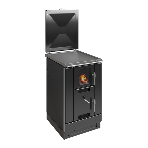
Page 4: Geräteaufbau
K158 Geräteaufbau K158F... -
Page 5: Legende
Legende 1. Abdeckhaube 2. Aschekasten 3. Aschetür 4. Brennstoffwagen 5. Heiztür 6. Kochlochdeckel 7. Kochplatte 8. Kurbel f. Hebe- und Senkvorrichtung 9. Rosttür 10. Rüttelstange 11. Sekundärluftschieber 12. Temperaturregler 13. Türgriff Herdzubehör Aschekasten Bedienungsanleitung Deckelheber Kurbel Rauchlochdeckelpaar kpl. Reinigungsbesen Russkratzer Schürhaken Das Wichtige kurz gesagt Der Herd darf auf gar keinen Fall angeheizt werden, wenn kein oder nur ungenügend... - Page 6 Antrag auf Zulassung einer Ausnahme nach § 22 der 1. BlmSchV eingereicht werden. Etwaige Forderungen von Behörden, Kunden oder Schornsteinfegern aufgrund nachträg- lich festgestellter Mängel bei den Aufstellungskriterien, fallen nicht unter den Verantwor- tungsbereich der Wamsler Haus- und Küchentechnik GmbH.
-
Page 7: Bedienung
1. BEDIENUNG 1.1 Inbetriebnahme als Integralherd Wenn der Heizungsherd in eine vorhandene Zentralheizungsanlage integriert wird und der Öl- oder Gaskessel zur Spitzenbedarfsdeckung in der Anlage verblieben ist, kann der Heizungsherd nach Belieben zugefeuert werden. Der Öl- oder Gaskessel sorgt dann in der Regel, während der Herd geheizt wird, nur noch für die Brauchwasserbereitung und sollte daher eine Abgasklappe zur Vermeidung unnötiger Stillstandsverluste besitzen. -
Page 8: Anzünden
Ebenso stellt der Kochlochdeckel die heißeste Stelle der Herdplatte dar. Sekundärluftschieber (11) (nur K158) Mit dem Sekundärluftschieber kann bei Winterstellung des Rostes die Luftzufuhr für die Nachverbrennung der Abgase geregelt werden. Bei Sommerstellung Schieber geschlossen halten (Bild 11 a). Brennstoffwagen (4) Der Brennstoffwagen wird in einer Mittelschiene geführt und kann durch Anheben über die... -
Page 9: Heizbetrieb Während Der Übergangszeit Und Im Sommer
Heizen mit Holz Sekundärluftschieber (11) „Auf“ (nur K158) Lange und starke Holzscheite in mindestens 2 Raten auf üppige Glut auflegen. Aufgespaltetes Brennholz verbessert die Verbrennungsgüte und die Regelbarkeit. Hartholz brennt ergiebiger als Weichholz. Bei zu niedrigem Schornsteinzug (evtl. hohe Außentem- peratur) und geregelter Unterluft durch den Temperaturregler kann nach der Brennstoff- aufgabe die Aschetür kurzfristig, unter Kontrolle geöffnet werden um die Verbrennung in... -
Page 10: Pflege Und Reinigung
Roststellung „oben“ Temperaturregler auf „3“ Sekundärluftschieber „zu“ (nur K158) In der wärmeren Jahreszeit wird der Herd meist nur zum Kochen und zur Warmwasserbe- reitung benutzt. Zu diesem Zweck bedient man sich der oberen Rostlage um zu gewähr- leisten, dass der Aufstellungsraum und der Warmwasserboiler sich nicht übermäßig er- wärmen. -
Page 11: Stahlplatte
Reinigen Sie Ihre Sichtscheibe und / oder Ceranplatte vor der ersten Benutzung mit einem feuchten sauberen Tuch. Verreiben Sie danach einige Tropfen eines Pflegemittels für Glaskeramik mit einem Küchenpapier auf der Scheibe / Ceranplatte. Nach dem Nachwischen und Trockenpolieren ist die hochwertige Oberfläche mit einem unsichtbaren Film überzogen. -
Page 12: Ursache Von Störungen
1.8 Ursache von Störungen Ihr Herd ist nach neuesten technischen Erkenntnissen gebaut. Dennoch können Störungen auftreten, die ihre Ursache im Schornstein, im Brennstoff oder in der Heizungsanlage ha- ben. Störung Überprüfung/Behebung Herd qualmt – - Kurzzeitiges Öffnen der Aschetür unter Kontrolle (hohe - im Sommer Außentemperaturen bedingen schlechten Schornstein zug). -
Page 13: Aufstellung
Im Sichtbereich (Strahlungsbereich) des Feuers muss zu brennbaren Bauteilen, Möbel oder auch z.B. zu Dekostoffen ein Abstand von mindestens 80 cm (K158F) und 50 cm (K158), gemessen ab Vorderkante Feuerraumtür eingehalten werden. Der Sicherheitsab- stand reduziert sich auf die Hälfte, wenn ein belüfteter Strahlungsschutz vor das zu schüt- zende Bauteil montiert wird. -
Page 14: Schornsteinanschluss
Anlagen nach DIN EN 12828 betrieben werden. Der Anschluss an eine offene Anlage schließt unsere Gewährleistung für Korrosionsschänden aus. Für offene Anlagen eignet sich der Heizungsherd K158, wenn kein Wärmetauscher für die thermische Ablaufsicherung eingebaut werden kann. -
Page 15: Abstandsverbindung Und Zubehör
Die thermische Ablaufsicherung hat im Zusammenwirken mit dem Wärmetauscher dafür zu sorgen, dass bei großem Feuer und geringer Abnahme an Heizungs-/Brauchwasser der Druck in der Heiztasche den zulässigen Höchstwert nicht überschreitet. Das Sicherheits- ventil muss deshalb regelmäßig auf seine Funktionsfähigkeit geprüft werden. Dies ge- schieht durch kurzzeitiges Drücken des roten Knopfes. - Page 16 Richtig Falsch min. 50 cm Querschnittsverengu ng im Schornstein durch ein zu weit eingeschobenes Abgasrohr Stau durch sich gegenseitig behindernde min. 30 cm Abgasströme Falschluft durch offene Türen an nicht benutzten Feuerstätten Falschluft durch offenen Rohranschluss Falschluft durch undichten Rohranschluss Falschluft durch offene Schornsteintür...
-
Page 17: Montage
3. MONTAGE 3.1 Montage der Abdeckhaube Die Abdeckhaube wird mit ihren Scharnierzapfen gleichmäßig in die Aufnahmehülsen des Herdrahmens (hinten rechts und links) gesteckt (Bild 23 und 24). Edelstahlabdeckhauben sind nicht lieferbar. 3.2 Wahl der Rohranschlussrichtung Der Rohrstutzen ist am Herd hinten montiert. Wird ein Abgasanschluss seitlich rechts oder links gewünscht, sind folgende Maßnahmen zu treffen: Den Rohrstutzen hinten abmontieren Die drei Befestigungsschrauben M4 lösen (Bild 25). -
Page 18: Montage Der Herdstange
3.4 Montage der Herdstange Für die Montage der Herdstange sind vorne unten am Herdrahmen (Bild 35) 2 Schrauben vormontiert. Heiztür öffnen Schrauben herausdrehen Herdstange mit einem Ende auf die Heiztür legen Herdstange am anderen Ende zuerst anschrauben. Zur besseren Zugänglichkeit zu den Schrauben können die beiden Blindblenden rechts und links der Heiztür leicht abgenommen werden. - Page 19 Die Heizungsanlagen sollen grundsätzlich mit einer Umwälzpumpe gebaut werden. Im einfachsten Installationsfall ist die Umwälzpumpe über einen Schalter an das Stromnetz angeschlossen und läuft dann in der Heizperiode im Dauerbetrieb, während die Leitung des Herdes mit dem eingebauten Temperaturregler geregelt wird. Die Pumpe kann jedoch auch von einem Maximumthermostat gesteuert werden.
-
Page 20: Integrierungen In Eine Bestehende Anlage
4.3 Integrierungen in eine bestehende Anlage Der Herd mit eingebautem Sicherheitswärmetauscher für die thermische Ablaufsicherung ist für den Einbau in eine bestehende Heizungsanlage geeignet, die als geschlossenes System ausgeführt ist. Die am Zentralheizungskessel im Keller angebrachten Sicherheitseinrichtungen können den Heizungsherd nicht mit absichern. Es sind für den Herd eigene Sicherheitseinrichtun- gen vorzusehen. -
Page 21: Heizleistungsdaten
Labor - Bedingungen nach EN 12815 in Bezug zu Füllmenge, Reglerstellung und untersten Roststellung für die Brennmaterialien Braunkohlebriketts und Scheitholz. Leistungstabelle nach DIN EN 12815-2005 Sekun- Tempe- Füllmenge / Gesamt- Wasser- Wärmeab- TYP K158 / Brenn- därluft ratur- Brenndauer Leistung Leistung gabe an den Stoff *... -
Page 22: Abmessungen, Leistungswerte, Abgaswerte
5.3 Abmessungen, Leistungswerte, Abgaswerte Gerätetyp K158 / K158F Bauart Mehrfachbelegung möglich Zulassung CE, 15a B-VG, VKF Außenmaße B x H x T (ohne Haube) Höhe mit geöffneter Abdeckhaube - siehe Maßskizze 5.4 - Höhe mit geschlossener Abdeckhaube Feuerraum, B x T 234 x 421 mm Feuerraumhöhe min/max. -
Page 23: Maßzeichnungen
5.4 Maßzeichnungen K158F K158 Vorlauf 1“ Rücklauf 1“ Wärmetauscheran- schluss f. tAS 3/8“ Die angeführten Abmessungsangaben sind nur zur Information! Wir behalten uns das Recht von Konstruktionsänderungen vor, falls diese das technische Niveau erhöhen, oder die Qualität ver- bessern! -
Page 24: Abbildungen
5.5 Kurzanleitung Anheizen Heizen Kochen Sekundär- luftschieber K158 Sekundär- luftschieber K158F Temperatur- Nach Bedarf Stufe 3 Stufe3 regler alle Typen siehe Kapitel 5.2 6. ABBILDUNGEN Bild 4 Bild 5 Bild 6... - Page 25 Bild 7 Bild 8 Bild 10 Bild 9 Bild 11...
- Page 26 Bild 12 Bild 13 Bild 14 Bild 15 Bild 17 Bild 16...
- Page 27 Bild 18 Bild 19 Bild 20...
- Page 28 Bild 23 Bild 24 Bild 25 Bild 26 Bild 27 Bild 28 Entsorgung des Gerätes Nach der Lebensdauer, das Gerät demontiert entsorgen. Die Teile sind fachge- recht in die entsprechenden Abfallsammelstellen / - Container zu entsorgen.
- Page 29 Bild 29 Bild 30 Bild 31 Bild 32 Bild 33 Bild 34 Bild 35 Bild 36...
-
Page 30: Sicherheitshinweise
7. SICHERHEITSHINWEISE 1. Die Geräte sind nach DIN EN 12815 geprüft (Typenschild). 2. Bei der Aufstellung und dem abgasseitigen Anschluss sind die anwendbaren nationa- len und europäischen Normen, örtliche und baurechtliche Vorschriften/Normen (z.B. DIN 18896, DIN 4705, DIN EN 13384, DIN 18160, DIN EN 1856-2, DIN EN 15287 u.a.) sowie feuerpolizeiliche Bestimmungen (z.B. - Page 31 22. Wenn Ausbesserungen oder Erneuerungen vorgenommen werden müssen, wenden Sie sich bitte rechtzeitig unter Angabe der genauen Art.Nr. und Fert.Nr. an Ihren Fach- händler. Es sind nur Original Wamsler - Ersatzteile zu verwenden. 23. Arbeiten, wie insbesondere Installation, Montage, Erstinbetriebnahme und Servicear- beiten sowie Reparaturen, dürfen nur durch einen ausgebildeten Fachbetrieb (Hei-...
- Page 35 • Functional safety by using proven technology, tested to the most stringent German and European Standards (EN 12815), • Long life by being built robustly. The K158/K158F central heating stove means you now own a modern compact unit to: • cook, bake, roast, •...
-
Page 36: Contents
Contents Foreword ....................... 33 Contents ........................ 36 Assembly ....................... 37 Legend ........................38 The most important at a glace ................38 1. OPERATION ..................... 39 1.1 Commissioning an integral stove..............39 1.2 Important operating parts ................39 1.3 Lighting ....................... 40 1.4 Heating and slow burning ................ -
Page 37: Assembly
Assembly K158 K158F... -
Page 38: Legend
Legend Top lid Ash pan Ash door Fuel trolley Fire door Fire hole cover Hotplate Crank for raising and lowering grate Grate door Riddle bar Secondary air slide Temperature control Fire door grip Stove accessories Ash pan Operation instruction Lid lever Crank Smoke hole cover pair complete Cleaning brush... -
Page 39: Operation
IMPORTANT Side air vents on chimneys with more than one stove connected not allowed. Clean stove, flue and chimney regularly. Do not lay any flue pipes horizontally for more than 1.25 m. Do not reduce flue pipe diameter from pipe connection to the chimney. Window and doors of the base frame should not be completely airtight because of the need for combustion air intake. -
Page 40: Lighting
Riddle arrangement The grate can be riddled in any height position using the riddle bar (10). If it hot then the lid lever can be used (Fig. 8). Please do not tip any glowing ashes in the dust bin or outside. Temperature controller (12) The Temperature control regulates the rate of burning through the air intake and thereby the stove's heat level. -
Page 41: Heating And Slow Burning
1.4 Heating and slow burning Heating with wood - Secondary air slide (11) "OPEN" Lay long and thick pieces of wood in at least two charges on thick embers. Split firewood improves the burning quality and controllability. Hardwood is more productive than soft- wood. -
Page 42: Care And Cleaning
Cooking in summer Grate position "UP" temperature control to "3" secondary air slide "OPEN" At the warmer times of the year, the stove will mostly only be used to cook, and prepare domestic hot water. Here the "UP" grate position is used, to ensure that the room where the stove is and the hot water tank do not become excessively overheated. -
Page 43: Causes Of Faults
1.8 Causes of faults Your stove is built to the latest technical know- how. Nevertheless faults may occur, which are caused by the chimney, fuel or the heating and plumbing. Fault Check / Rectify Stove smokes - open the ash door briefly. High outside temperatures - in summer cause poor chimney draught. -
Page 44: Arrangement
2. ARRANGEMENT For installation and for connection of flue, the requirements of the Fire Regulations (FeuVO in Germany) apply, as well as local building regulations such as the following technical standards DIN 4705, EN 13384, DIN 18160, EN 1856-2, EN 12828, EN 12831, EN 12897 and EN 15287. -
Page 45: The Heating Stove For Open And Closed Systems
The heating stove for open and closed systems Heating stove model K157/K158 is only allowed to operate with heat sink in closed sys- tems according to EN 12828, EN 12831 and EN 12897. If it is connected to an open sys- tem then our guarantee for corrosion damage becomes invalid. - Page 46 Right Wrong min. 50 cm Chimney diameter reduced due to flue being inserted too far into chimney Blockage due to exhaust gases interfering with min. 30 cm each other Air leak due to ppen doors on stove which is not in use Air leak from open pipe connection Air leak from...
-
Page 47: Installation
3. INSTALLATION 3.1 Installing the top lid The top lid hinge spigots are inserted evenly into the plug holes in the stove frame (at back, left and right) (Fig. 23 & 24). 3.2 Flue gas connector direction The pipe connector is factory installed at the back of the stove. If a flue gas connection is required on the side, left or right, the following steps should be taken: Remove the pipe connector at the back by undoing the three fixing bolts M4 (Fig. -
Page 48: Instructions
4. INSTRUCTIONS 4.1 General information The following directions and instructions concern questions of fundamental importance. It is further presupposed that the installer of a heating plant has the necessary technical and craftsman's basic knowledge for the task. This is naturally also the assumption where the stove is being incorporated as an integrated stove into an existing system. - Page 49 Where there is a lower distribution ventilating valve it must be provided on each radiator. The radiators should not be inclined towards the ventilation. As radiators are usually at the same level on the floor where the stove is installed, these radiators should all be connected to a circulating pump as matter of course.
-
Page 50: Integrating In An Existing Unit
Before commissioning installation water must be fed through the filling and emptying cock until water flows out of the overflow on the open expansion vessel. In the case of a closed system, an over pressure of 1 to 1.5 bar must be created. In any case attention has to be paid to slowly filling the system and the exhausting air through the integrated ventilation valve before the above mentioned static pressure is reached or before the expansion ves- sel overflows. -
Page 51: Technical Data
5. TECHNICAL DATA Fuel Low smoke, trouble-free operation of the stove and a supply of heat at the nominal level with a chimney draught of 12 Pa are only guaranteed when you use the following fuels and no others. Only use natural, dry chopped firewood with a remaining humidity of max. 20% and lignite (brown coal) briquettes. -
Page 52: Heating Output Data
5.2 Heating output data The following table shows burning time, water output and heat emission (to the room where it is installed) of your stove under normal conditions according to EN 12815 con- cerning the charge quantities and control setting for the fuel materials coal and wood. Output table according to EN 12815:2005 Heat Total... -
Page 53: Dimensions, Output Values, Flue Gas Values
5.3 Dimensions, output values, flue gas values Model K158 / K158F Registration CE, 15a B-VG, VKF External dimensions W x H x D (without lid) Height with top lids open See dimensional drawing 5.4 Height with top lids closed Fire box W x D... -
Page 54: Dimensional Drawings
5.4 Dimensional drawings Model K158 / K158F K158F K158 flow 1” return heat exchanger connection for tAs 3/8“ We reserve the right to make changes which relate to technical advances and / or to an improvement in quality. We accept no liability for printing errors and changes which occur after printing. -
Page 55: Brief Instructions
5.5 Brief instructions Heating up Heating Cooking Secondary air slider CLOSED OPEN OPEN K158 Secondary air slider K158F Temperature control According to need Setting 3 Setting 3 See 5.2 6. FIGURES Pic. 4 Pic. 5 Pic. 6... - Page 56 Pic. 7 Pic. 8 Pic. 10 Pic. 9 Pic. 11...
- Page 57 ____________________________________________________________ Pic. 12 Pic.13 Pic. 14 Pic. 15 Pic. 16 Pic. 17...
- Page 58 ____________________________________________________________ Pic. 18 Pic. 19 Pic. 20...
- Page 59 Pic. 23 Pic. 24 Pic. 25 Pic. 26 Pic. 27 Pic. 28...
- Page 60 ____________________________________________________________ Pic. 29 Pic. 30 Pic. 31 Pic. 32 Pic. 33 Pic. 34 Pic. 36 Pic. 35...
-
Page 61: Safety Measures
7. SAFETY MEASURES The stoves are tested to EN 12815 (see identification plate). For installation and for flue gas connections, the requirements of the Fire Regulations (FeuVO in Germany) apply, as well as local building regulations such as the following technical standards DIN 4705, EN 13384, DIN 18896, DIN 18160, EN 1856-2 and EN 15287. - Page 62 18. If repairs or replacements are necessary, please contact your supplier with the nec- essary article numbers and serial numbers in good time. Only original WAMSLER re- placement parts may be used. 19. Work such as installation, setup, commissioning and services, as well as repairs, must only be carried out by qualified personnel (heating system or space heating technicians).
-
Page 63: Préface
Préface Cher client, Nous vous félicitons d’avoir fait l’acquisition de notre cuisinière à combustible solide. Vous avez fait le bon choix. Ce produit vous donne en effet la garantie • d’une qualité élevée obtenue grâce à l’utilisation des matériaux les meilleurs et les mieux éprouvés, •... -
Page 64: Sommaire
5.1 Combustible ....................76 5.2 Dates de puissance ..................77 5.3 Dimensions, valeurs, valeurs des gaz ............78 5.4 Plans avec les dimensions Type K158 ............79 5.5 Instructions brèves et dessins ..............80 6. FIGURES ......................80 7. CONSIGNES DE SÈCURITÉ ................86... -
Page 65: Structure De L'appareil
Structure de l’appareil K158 K158F... -
Page 66: Légenda
Légenda couvercle (accessoire hors série) cendrier porte du cendrier porte du four tiroir de rangement manomètre porte de chargement du foyer couvercle dans la plaque de cuisson plaques de cuisson 10. clapet pour nettoyage 11. couvercle sortie fumée 12. manivelle pour monter et baisser la grille 13. -
Page 67: Fonctionnement
Avec la grille en position basse (hiver) charger la chambre de combustion peu à peu! Ne surchauffez jamais votre dessus en acier, et ne laissez rien déborder sur le dessus en acier ! Le tirage de la cheminée ne doit pas être en dessous de 12 Pa en plein régime. En cas que le tirage de la cheminée pour la cuisinière est trop fort il est nécessaire d´installer en clapet additionnel d´entrée d´air. -
Page 68: Allumage
Régulateur de température (16) Le régulateur de température contrôlé´entrée d’air et ainsi la combustion et la puissance de la cuisinière. Régulateur des fonctions (19) Avec le lève couvercle vous pouvez régler le régulateur selon la fonction désirée. (Image7). Vous avez le choix de trois positions. I. -
Page 69: Chauffage Central Et Chauffage Continue
ATTENTION ! Dans l´intérêt de l´environnement n´utilisez pas du papier et replissez le foyer len- tement (entre 10 et 15 min.) avec le combustible. AVERTISSEMENT! Quand une fois la cuisinière est en fonction, n´utiliser jamais une hotte dans le même lieu. Vous risquez d´aspirer des gazes de la cuisinière. -
Page 70: Cuire
- Nettoyez les parois émaillées avec de l´eau froide avec un peu de savon. Après séchez - Le dessus en acier poli peut être enduit avec de l´huile exempte d´acide. Il existe égale- ment un produit de nettoyage » WAMSLER » que vous pouvez commander chez votre revendeur. -
Page 71: Surface De Verre-Céramique
1.7.1. Surface de verre-céramique Nettoyez votre vitre et/ ou votre plaque de céramique avant la première utilisation à l’aide d’un chiffon humide propre. Appliquez ensuite quelques gouttes d’un produits de soin pour le verre céramique à l’aide d’un essuie-tout en papier sur la vitre / la plaque de céramique. Après avoir été... -
Page 72: Installation
sécurité thermique en fonction - la porte de décentrage est elle fermée ? - vissez la grille vers le haut. Eau de condensation dans la - le combustible est il humide? cuisinière - la température de retour est trop basse ? 2. -
Page 73: Cuisinière Chauffage Central Pour Systèmes Ouvert Ou Fermé
2.3 Cuisinière chauffage central pour systèmes ouvert ou fermé La cuisinière ne doit être installée avec un dispositif de sécurité et une protection ther- mique que dans un circuit fermé selon EN 12828. Pour une installation ouverte n´utilisez jamais une protection thermique et un dispositif de sécurité. -
Page 74: Montage De La Barre
Selon le besoin, les éléments peuvent être installés dans la cuisinière comme suit : • Glissez le senseur du dispositif de sécurité jusqu´au font (image 31) • Fixez le tuyau de protection (image 32) • Pour monter la protection thermique dévissez la plaque arrière de la chaudière et introduisez la protection thermique (image 33) ATTENTION: La protection thermique et la chaudière doivent être étanche (image 34). -
Page 75: Notices Pour Installation Du Système De Chaffage Central Et De L'eau Sanitaire
4. NOTICES POUR INSTALLATION DU SYSTÈME DE CHAFFAGE CENTRAL ET DE L’EAU SANITAIRE 4.1 Informations générales Il est absolument nécessaire que l´installation soit faite d´un spécialiste qualifié. Cela est aussi valable pour l´installation de la cuisinière dans un système existent. Maintenez toutes les normes locales comme EN 12828, EN 12831 et EN 12897. -
Page 76: Donnèes Techniques
Attention! Si le tirage de la cheminée est insuffisant, vous pouvez avoir une sortie des gaz en ouvrant la porte du foyer. Ouvrez la porte lentement d’abord et après peut à peut. Pour ajouter du combustible attendez que vous avez seulement de la braise dans le foyer et éviter de charger quand il y a encore des flammes. -
Page 77: Dates De Puissance
5.2 Dates de puissance Le tableau suivant indique la durée de combustion, puissance vers l´eau et la radiation de votre cuisinière sous des conditions norme aux selon EN 12815 en relation avec la position du réglage de température et la quantité de combustible pour lignite et bûches. Tableau des valeurs selon EN 12815 :2005 rendement réglage... -
Page 78: Dimensions, Valeurs, Valeurs Des Gaz
5.3 Dimensions, valeurs, valeurs des gaz K158 / K158F Modèle Autorisation de mise sur le marché CE, 15a B-VG, VKF Dimensions externes LxHxP (sans couvercle) Hauteur avec couvercle ouvert - voir croquis 5.4 - Hauteur avec couvercle fermé Foyer LxP 234 x 421 mm Hauteur du foyer min. -
Page 79: Plans Avec Les Dimensions Type K158
5.4 Plans avec les dimensions Type K158 / K158F K158F K158 départ 1“ retour 1“ connection protection termique 3/8“ tAs arrière de la cuisinière... -
Page 80: Instructions Brèves Et Dessins
Régulateur de fonc- Cuire hiver II ou allumage Chauffage tion III, en été I Régulateur de l´air fermé ouvert ouvert secondaire K158 Régulateur de l´air secondaire K158F Régulateur de tem- Selon besoin Position 3 Position 3 pérature 6. FIGURES fig. 4 fig. - Page 81 fig. 8 fig. 7 fig. 10 fig. 9 fig. 11...
- Page 82 fig. 12 fig.13 fig. 14 fig. 15 fig. 16 fig. 17...
- Page 83 fig. 18 fig. 19 fig. 20...
- Page 84 fig. 23 fig. 24 fig. 25 fig. 26 fig. 27 fig. 28...
- Page 85 fig. 30 fig. 29 fig. 31 fig.32 fig. 33 fig. 34 fig. 35 fig. 36...
-
Page 86: Consignes De Sècurité
7. CONSIGNES DE SÈCURITÉ Les appareils ont été contrôlés selon les normes EN 12815 (Plaque signalétique). Pour la mise en place des appareils et le raccordement aux cheminées d’évacuation des gaz, on devra observer les exigences énoncées par les directives concernant les appa- reils de chauffage (FeuFO en Allemagne) ainsi que les normes DIN 4705, EN 13384, DIN 18160, EN 1856-2, EN 12828, EN 12831, EN 12897 et EN 15287. - Page 87 à temps à votre commerçant spécialisé en lui indiquant exactement le numéro de référence et le numéro de fabrication. On ne peut utiliser que des pièces originales WAMSLER. Les travaux, tels que, en particulier, l’installation, le montage, la première mise en ser- vice, les travaux de maintenance ainsi que les réparations ne pourront être effectués que...
-
Page 88: Prefazione
Funzionamento sicuro grazie ad un’avanzata tecnologia rigorosamente testata secondo la norma europea EN 12815. Lunga durata nel tempo grazie alla robusta struttura. Con la termocucina K158/K158F lei dispone di un moderno apparecchio che ac- corpa le seguenti funzioni cucinare sulla piastra riscaldamento centrale produzione indiretta dell’acqua calda... -
Page 89: Indice
Indice Prefazione ......................88 Indice ........................89 Struttura dell’apparecchio ..................90 Legenda ........................ 91 Note in breve ......................91 1. USO ........................92 1.1 Messa in funzione della termocucina ............92 1.2 Comandi principali ..................93 1.3 Accendere ....................94 1.4 Riscaldamento e utilizzo continuo .............. -
Page 90: Struttura Dell'apparecchio
Struttura dell’apparecchio K158 K158F... -
Page 91: Legenda
Legenda 1. Coperchio isolante 2. Cassetto cenere 3. Porta cenere 4. Cassetto combustibile 5. Sportello focolare 6. Coperchio foro di cottura 7. Piastra di cottura 8. Manovella per regolazione altezza 9. Sportello griglia 10. Leva di scuotimento 11. Serranda aria secondaria 12. -
Page 92: Uso
Non fare disassamenti orizzontali del condotto di raccordo alla canna fumaria che superino 1,25 m! Il tubo di scarico fumi (evacuazione fumi) deve avere lo stesso diametro della canna fumaria! Per garantire un apporto di aria comburente adeguato, le finestre e le porte del locale d’installazione non devono essere a tenuta stagna! Durante l’installazione della cucina e la posa del tubo di scarico fumi osservare le norme antincendio! -
Page 93: Comandi Principali
1.2 Comandi principali Manovella (8) Alzando o abbassando la griglia della cucina, si passa dal funzionamento estivo a quello invernale e viceversa. Per regolare la griglia si usa la manovella (8) in dotazione (fig. 4 + 5). Il funzionamento estivo (posizione superiore) (fig. 4) consente un’alta potenza per cucinare, con minore riscaldamento dell’acqua. -
Page 94: Accendere
Non depositare nel cassetto porta legna materiali facilmente infiammabili (carta, accendi fuoco da grill, spirito ecc.). Avvertenza Quando la cucina è in funzione, si può aprire lo sportello fuoco e lo sportello cenere con l’aiuto del guanto di protezione (fig. 13). 1.3 Accendere Con la griglia nella posizione inferiore (invernale) Aprire gli sportelli cenere, fuoco e griglia, posizionare sulla griglia la diavolina o trucioli di... -
Page 95: Riscaldamento Durante Le Mezze Stagioni E In Estate
Riscaldare a carbone - serranda dell’aria secondaria (11) “aperta” Caricare con carbone solo dopo che si sia formato un letto di brace sufficiente, dividendo il combustibile almeno in 2 cariche, a intervalli di circa 15 minuti. Utilizzo continuo a carbone Abbassare il termoregolatore (12) solo quando dallo strato di carbone aggiunto escono delle fiammelle gialle. -
Page 96: Pulizia E Manutenzione
1.7 Pulizia e manutenzione Gli intervalli da rispettare per la pulizia della cucina del tubo di scarico dipendono innanzi tutto dal combustibile usato, dal tiraggio della canna fumaria/camino e dal tipo di servizio. In ogni caso si deve pulire quando diminuisce la potenza termica nonostante vi sia un abbondante apporto di aria (sportello cenere aperto) il combusti- bile brucia male... -
Page 97: Cause E Risoluzioni Di Anomalie
1.8 Cause e risoluzioni di anomalie La vostra cucina è stata costruita secondo le più avanzate conoscenze tecniche. Si posso- no però verificare dei disturbi che sono da attribuire al camino/canna fumaria, al combusti- bile oppure all’impianto di riscaldamento. Anomalia Controllo/rimedio Dalla cucina esce fumo - in estate... -
Page 98: Installazione
2. INSTALLAZIONE Per l’installazione e il collegamento del lato gas sono da rispettare la norma FeuVO per gli impianti di combustione (Germania), le norme nazionali italiane, i regolamenti edilizi locali, nonché le norme DIN 4705, EN 13384, DIN 18160, EN 1856-2, EN 12828, EN 12831, EN 12897 e EN 15287. -
Page 99: Il Camino Come Elemento Funzionale Della Cucina
Il collegamento con un impianto aperto esclude la nostra garanzia in caso di danni di cor- rosione. La termocucina K158 è idonea per impianti aperti se non si installa uno scambiatore con valvola di scarico termico. Per ulteriori informazioni sull’impianto di riscaldamento centrale vedi punto 4. -
Page 100: Distanziali E Accessori
La valvola di scarico termico impedisce che la pressione della caldaia superi il valore mas- simo consentito in caso di forte combustione e scarso fabbisogno di acqua sanitaria /riscaldamento. Per questo motivi, il funzionamento corretto della valvola di sicurezza deve essere controllato a intervalli regolari. - Page 101 Giusto Giusto Sbagliato Più basso del bordo del camino almeno 50 cm Nessun altro focolare collegato alla canna fumaria Immissione di aria Raccordi non utilizzati attraverso raccordo perfettamente chiusi aperto Immissione di aria attraverso raccordo Raccordo ben non ermetico ermetico - per esempio tramite manicotto isolante doppio...
-
Page 102: Montaggio
3. MONTAGGIO 3.1 Montaggio del top isolante I I top isolanti si montano inserendo i perni delle cerniere nelle sedi a boccola del telaio (di dietro a destra e sinistra) (fig. 23/24). 3.2 Posizionamento del raccordo Il collarino dell’uscita fumi è montato sul retro della cucina. Se si desidera portare lo scari- co dei gas combusti su un lato, procedere nel modo seguente: Smontare il raccordo sul retro allentando le 3 viti di fissaggio M4 (fig. -
Page 103: Indicazioni Sull'impianto Dell'acqua Di Riscaldamento/Sanitaria
4. INDICAZIONI SULL’IMPIANTO DELL’ACQUA DI RISCALDAMEN- TO/SANITARIA 4.1 Informazioni generali Le seguenti indicazioni e istruzioni riguardano solo i punti più importanti. Si presuppone comunque che chiunque metta in funzione un impianto di riscaldamento disponga delle necessarie conoscenze sia tecniche che pratiche di base. Ciò vale ovviamente anche per l’inserimento successivo della cucina, come termocucina, in un impianto già... - Page 104 Negli impianti a cascata, la pendenza delle tubazioni orizzontali non deve essere inferiore a 0,5 cm/m. Termosifoni con oltre 25 elementi o i radiatori a piastre la cui lunghezza superi 1,5 m de- vono essere collegati diagonalmente alternati alle tubazioni di mandata e di ritorno. In caso di una distribuzione dal basso, si deve prevedere una valvola di sfiato per ogni radiatore.
-
Page 105: Integrazione In Un Impianto Esistente
Vasi di espansione, boiler e tubazioni, se installati nel soffitto, devono essere efficacemen- te protetti dal gelo. Se l’impianto durante l’inverno non viene attivato per un periodo prolungato, è necessario scaricarlo. Aprire radiatori, valvole di sfiato e altri elementi di rilevazione. Prima di mettere in servizio un impianto, riempirlo di acqua, attraverso il rubinetto di carico e di scarico, finché... -
Page 106: Schede Tecniche
5. SCHEDE TECNICHE 5.1 Guida combustibili Per garantire un corretto funzionamento della cucina con i emissioni di fumo, nonché il mantenimento della potenza nominale indicato per un tiraggio di 12 Pa, utilizzare esclusi- vamente i combustibili elencati di seguito. Si raccomanda di utilizzare solo legna secca allo stato naturale con umidità... -
Page 107: Dati Della Potenza Termica
Tabella della potenza secondo DIN EN 12815:2005 Quanti- Rendi- Rendi- Rendi- Termo- aria modello combu- tà di mento mento mento al regola- secon- K158 stibile * carico totale dell’acq locale kW tore daria in kg kW** ua kW** Potenza Carbone 10,6 nominale con... -
Page 108: Dimensioni, Valori Potenza Ed Emissioni
5.3 Dimensioni, valori potenza ed emissioni Modello K158 / K158F Direttive CE, VKF, 15aB-VG Dimensioni esterni L x A x P (senza coperchio) - vedi disegni dimensionali Altezza con coperchio aperto 5.4 - Altezza con coperchio chiuso Camera di combustione L x P 234 x 421 mm Camera di combustione altezza min. -
Page 109: Disegni Dimensionali
5.4 Disegni dimensionali Modello K158 / K158F K158F K158 mandata 1“ ritorno 1“ Allacciamento scambiatore ter- mico con valvola di scarico termico ⅜”... -
Page 110: Istruzioni Brevi
5.5 Istruzioni brevi Accendere Riscaldare Cucinare piastra Serranda dell’aria CHIUSA APERTA APERTA secondaria K158 Serranda dell’aria secondaria K158F a secondo della Termoregolatore Grado 3 Grado 3 necessità (5.2) 6. FIGURE fig. 4 fig. 5 fig. 6... - Page 111 fig. 8 fig. 7 fig. 10 fig. 9 fig. 11...
- Page 112 fig. 12 fig.13 fig. 14 fig. 15 fig. 16 fig. 17...
- Page 113 fig. 18 fig. 19 fig. 20...
- Page 114 fig. 23 fig. 24 fig. 25 fig. 26 fig. 27 fig. 28...
- Page 115 fig. 29 fig. 30 fig. 31 fig.32 fig. 33 fig. 34 fig. 35 fig. 36...
-
Page 116: Avvertenze Di Sicurezza
7. AVVERTENZE DI SICUREZZA Gli apparecchi sono stati testati sulla base della norma EN 13240 o secondo EN 12815 (vedi targhetta di identificazione) Per un funzionamento ottimale della sua cucina è fondamentale che la canna fumaria alla quale volete effettuare il collegamento sia in condizioni perfette. •... - Page 117 17. Per eventuali riparazioni o sostituzioni contattare tempestivamente il proprio rivendito- re avendo cura di comunicare l’esatto codice articolo e di serie dell’apparecchio. Tutti i componenti dovranno essere sostituiti esclusivamente con pezzi originali Wamsler. 18. L’apparecchio deve disporre dell’apporto di aria necessario per la combustione che sottrae al locale d’installazione, per cui è...
- Page 120 Wamsler Haus- und Küchentechnik GmbH • Adalperostr. 86 • • D-85737 Ismaning • Tel. +49 (0)89 / 320 84-0 • Fax +49 (0)89 / 320 84-238 info@wamsler.eu • www.wamsler.eu © Wamsler Haus- und Küchentechnik GmbH, 85737 Ismaning. Alle Rechte und Änderungen vorbehalten.
Need help?
Do you have a question about the K158 and is the answer not in the manual?
Questions and answers