Table of Contents
Advertisement
Quick Links
®
International registered trademark n. 2.777.971
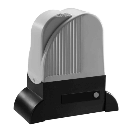
LEPUS 1000
(110V)
MOTOR REDUCER FOR SLIDING GATES
SCHUIFHEKMOTOR
SEA USA Inc.
10850 N.W. 21st unit 160 DORAL MIAMI
Florida (FL) 33172
Phone:++1-305.594.1151 Fax: ++1-305.594.7325
Toll Free: 800.689.4716
web site: www.sea-usa.com
e-mail: sales@sea-usa.com
Cod. 67410022
REV 00 - 12/2013
Advertisement
Table of Contents

Related Manuals for SEA USA LEPUS 1000

Summary of Contents for SEA USA LEPUS 1000
- Page 1 ® International registered trademark n. 2.777.971 LEPUS 1000 (110V) MOTOR REDUCER FOR SLIDING GATES SCHUIFHEKMOTOR SEA USA Inc. 10850 N.W. 21st unit 160 DORAL MIAMI Florida (FL) 33172 Phone:++1-305.594.1151 Fax: ++1-305.594.7325 Toll Free: 800.689.4716 web site: www.sea-usa.com e-mail: sales@sea-usa.com Cod. 67410022...
- Page 2 ® International registered trademark n. 2.777.971 Details General An appliance shall be provided with an instruction manual. The instruction manual shall give instructions for the installation, operation, and user maintenance of the appliance. The installation instructions shall specify the need for a grounding-type receptacle for connection to the supply and shall stress the importance of proper grounding.
-
Page 3: Important Safety Instructions
® International registered trademark n. 2.777.971 g) The Stop and/or Reset button must be located in the line-of-sight of the gate. Activation of the reset control shall not cause the operator to start. h) A minimum of two (2) WARNING SIGNS shall be installed, one on each side of the gate where easily visible. i) For gate operators utilizing a non-contact sensor: 1) See instructions on the placement of non-contact sensors for each Type of application, 2) Care shall be exercised to reduce the risk of nuisance tripping, such as when a vehicle, trips the sensor while the gate is... -
Page 4: Mechanical Installation
Adjusting screw mechanical clutch Anchor bolts Electronic control unit Angular cover Oil filling up cap Pinion Magnetic encoder Lever release reducer DIMENSIONS (inches) LEPUS 1000 110V TECHNICAL DATA Power Supply 115 V (±5%) 50/60 Hz Power 350W Motor capacitor µF 1. GATE ARRANGEMENT... -
Page 5: Type Of Installation
® International registered trademark n. 2.777.971 GATE WARNINGS AND PRECAUTIONS points. Install the warning signs, on both sides of the gate which informs the f) The top guide must be manufactured and installed so that the gate is pedestrians about the danger they run when passing or resting in the perfectly upright. -
Page 6: Mounting Plate Installation
® International registered trademark n. 2.777.971 MECHANICAL INSTALLATION 4. MOUNTING PLATE INSTALLATION 5. PINION ASSEMBLING 5.1. Put the spline into the motor reducer shaft as in Fig. 14. To install the mounting plate it is necessary to: 5.2. Mount the pinion on the motor as shown in fig.14. 4.1. -
Page 7: Limit Switch Adjustment
® International registered trademark n. 2.777.971 MECHANICAL INSTALLATION 7. GEAR RACK MOUNTING 7.7. Make sure that the gear rack works at the center of the pinion along all rack elements, if necessary, adjust the distance 7.1. Release the motor reducer and take the leaf to complete pieces length. -
Page 8: Clutch Adjustment
® International registered trademark n. 2.777.971 MECHANICAL INSTALLATION 9. GROUNDING (Fig. 27) Mechanical limit switch Fig. 27 Fig. 23 10. CLUTCH ADJUSTMENT Inductive limit switch 10.1.Take power supply tension off. 10.2.To adjust the clutch act as follows: - Act on the “A” screw (Fig. 28) in the following way: - Clockwise = less clutch sensibility and more pushing force - Anti-clockwise = more clutch sensibility and less pushing force Fig. -
Page 9: External Release (Optional)
® International registered trademark n. 2.777.971 MECHANICAL INSTALLATION Notice: the holes for the chain tensioner and so the chain itself must be to a minimum distance of 1,77 in. from the gate (Fig.32). 11.2. Install the chain making it pass through the pinion group as in Fig.29. -
Page 10: Cable Layout
® International registered trademark n. 2.777.971 MECHANICAL INSTALLATION 13. BREATHER SCREW REPLACEMENT Replace the breather screw before startup. Fig. 36 Fig. 37 CABLE LAYOUT (Fig. 38) Fig. 38 1) LEPUS operator 2) Left photocell 3) Right photocell 4) Pneumatic safety edge 8) Warning notice 5) Key switch 9) Electronic control unit or j... -
Page 11: Periodical Maintenance
(Fig. 39). The guarantee will be void and the manufacturer responsibility - Pull the release lever until it stops, about 90° approximately will be nullified if SEA USA original spare parts are not being (Fig. 40). used. Note: when you pull the release lever, the electronic control... - Page 12 SEA. Recognized defects, whatever their nature, will not produce any responsibility and/or damage claims to SEA USA Inc and SEA s.r.l. Warranty shall not cover any required labor activities. Warranty will in no case be recognized if alterations and any other changes will be found on products. Warranty will not cover damages caused by carriers, expendable materials and faults due to improper use with the products specifications.
Need help?
Do you have a question about the LEPUS 1000 and is the answer not in the manual?
Questions and answers