Table of Contents
Advertisement
Quick Links
1
2
3
4
44
5
43
6
42
17
41
18
40
39
19
36
38
35
37
20
34
33
32
31
30
27
26
29
28
25
24
23
22
21
Power Connector/ 电源
System Panel Header/ 前面板
No.
Pin Define
1
GND
3
1
2
GND
1
2
4
2
3
+12V
4
+12V
Battery Cable Connector
9
10
No.
Pin Define
1
Battery+
2
1
2
GND
SATA Connector/SATA 接口
Embedded Display Port Connector
1
2
No.
Pin Define
7
1
No.
Pin Define
1
GND
1
GND
2
TXP
2
GND
3
TXN
3
eDP_0-
4
GND
4
eDP_3-
5
RXN
5
eDP_0+
1
7
6
eDP_3+
6
RXP
7
GND
7
GND
7
1
8
-eDPSW
9
eDP_1-
10
GND
NOTE!
Please ensure pin 8 is connected to Ground.
Hard Drive Power Connectornnector
Audio Amplifier Connector
4
No.
Pin Define
No.
1
+12V
1
2
GND
4
1
2
3
GND
3
1
4
VCC
4
2
4
1
3
6
5
PN:xxxxxxxxxxxxxxxxxxxxxx
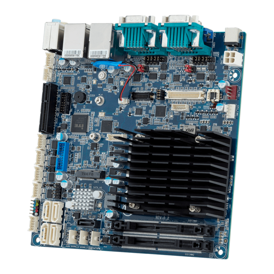
MZGLKAI Quick Reference Guide/ 快速测试参考指南
9
10
No.
Code
1
AUDIO
2
USB30_LAN1
3
USB20_LAN2
4
HDMI_COM2
11
5
JCOM22
8
JRS23/JRS22/
JRS24/JRS21
7
(right to left)
6
JCOM21
12
15
7
JCOM11
16
14
13
8
JCOM12
JRS13/JRS12/
JRS14/JRS11
(right to left)
9
VGA_COM1
10
DC_IN1
11
DC_IN2
12
SYS_FAN
13
CPU_FAN
14
BKL_CN
CPU
15
LVDS
16
LSW
17
EDP
18
BATTERY
19
GPIO_CNT
20
CNVI
21
SATAIII_0
22
SATAPW_1
23
SATAPW_3_4
SODIMM1
24
SATAPW_1_2
25
SATAIII_1
SODIMM2
26
SATAIII_2
27
SATAIII_4
28
SATAIII_3
Memory Population Configuration/ 安装内存
No.
Pin Define
1
HDD LED+
2
Power LED+
3
HDD LED-
4
Power LED-
5
GND
6
Power Button+
7
Reset Button
8
Power Button-
9
No Connect
10
No Pin
19
No.
Pin Define
20
1
VCC3
No.
Pin Define
2
VCC
11
eDP_1+
1
39
3
VCC3
12
eDPAUX-
4
VCC
13
GND
5
SPC0
14
ePDAUX+
2
40
15
eDP_2-
6
SPD0
16
GND
7
GND
17
eDP_2+
8
GND
18
eDP_HDP_C
9
A1P_C
19
VCC_LVDS
10
A0P_C
20
VCC3_LVDS
Front Audio Connector/ 前置音频
1
9
No.
Pin Define
No.
1
MIC_L
6
2
GND
7
Pin Define
3
MIC_R
8
2
10
Speaker Out L+
4
-ACZ_DET
9
Speaker Out L-
5
HPOUT_R
10
Speaker Out R-
Speaker Out R+
Jumper Settings/ 跳线设置
No.
Desription
1
5V/12V/RI signal select jumper for Serial port header#1 (JCOM11)
2
6
Pin No.
Definition
1-2 Close: 5V (Power COM)
1
5
1
VCC
2
RI1-/5V/12V
2
6
3-4 Close: RI (Stand COM)
1
5
3
NRI1-
4
RI1-/5V/12V
2
6
5-6 Close: 12V (power COM)
5
+12V
1
5
6
RI1-/5V/12V
2
RS232/RS422/RS485 select jumper for Serial port header#1
(JCOM12/JRS13/JRS14/JRS11/JRS12)
2
6
1-2 Close: RS232
Pin No.
Definition
1
5
1
RXD232
2
6
3-4 Close: RS422
1
5
2
RXD1
2
6
5-6 Close: RS485
1
5
3
RXD422
1-2 Close: RS422/RS485
4
RXD1
2-3Close: RS232 (Default setting)
5
RXD485
6
RXD1
Description
Audio connectors
GbE LAN port#1 (top)/USB 3.0 ports (bottom)
GbE LAN port#2 (top)/USB 2.0 ports (bottom)
COM port #2 (top)/HDMI port (bottom)
RS232/RS422/RS485 select jumper for serial port#2
5V/12V/RI signal select jumper for serial port#2
5V/12V/RI signal select jumper for serial port#1
RS232/RS422/RS485 select jumper for serial port#1
COM port #1 (top)/VGA port (bottom)
DC In power connector
DC In 12V power connector
System fan connector
CPU fan connector
Back light brightness control connector
LVDS connector
LVDS resolution jumper
Embedded Display Port connector
Battery cable connector
GPIO connector
CNVI connector
SATA 6Gb/s connector#0
Hard disk power connector (for SATA port #0)
Hard disk power connector (for SATA port #3 & #4)
Hard disk power connector (for SATA port #1 & #2)
SATA 6Gb/s connector#1
SATA 6Gb/s connector#2
SATA 6Gb/s connector#4
SATA 6Gb/s connector#3
LAN Port Active LED Header
No.
Pin Define
1
2
1
Active
2
GND
CPU/System FAN/ 风扇
1
No.
Pin Define
1
GND
2
+12V
3
Sense
4
4
Speed Control
LVDS
No.
Pin Define
No.
Pin Define
No.
Pin Define
11
A1M_C
21
A5P_C
31
GND
12
A0M_C
22
A4P_C
32
GND
13
GND
23
A5M_C
33
CLK2P_C
14
GND
24
A4M_C
34
CLK1P_C
15
A3P_C
25
GND
35
CLK2M_C
16
A2P_C
26
GND
36
CLK1M_C
17
A3M_C
27
A7P_C
37
GND
18
A2M_C
28
A6P_C
38
GND
19
GND
29
A7M_C
39
+12V
20
GND
30
A6M_C
40
+12V
Back Light Brightness Control Connector
Pin Define
No.
Pin Define
GND
1
VCC_LVDS
FAUDIO_JD
2
PWM_OUT
1
5
No Connect
3
EN_BKLT
HPOUT_L
4
GND
GND
5
+12V_LVDS
No.
Desription
3
5V/12V/RI signal select jumper for Serial port header#2
2
6
Pin No.
Definition
1-2 Close: 5V (Power COM)
1
5
1
2
RI2-/5V/12V
2
6
3-4 Close: RI (Stand COM)
1
5
3
4
RI2-/5V/12V
2
6
5-6 Close: 12V (power COM)
5
1
5
6
RI2-/5V/12V
4
RS232/RS422/RS485 select jumper for Serial port header#1
(JRS21/JRS22/JRS23/JRS24/JCOM22)
6 5
1-2 Close: RS232
Pin No.
2 1
1
6 5
2
3-4 Close: RS422
3
2 1
4
6 5
5-6 Close: RS485
5
2 1
6
1-2 Close: RS422/RS485
2-3Close: RS232 (Default setting)
No.
Code
Description
29
RAID_LED
RAID LED header
30
SYS_PANEL
Front panel header
31
FUSB2
USB 2.0 header
32
COM6
Serial port cable connector#6
33
AT_CN
AT/ATX power mode select jumper
34
U2LAN_LED
Active LED for LAN port#1
35
U3LAN_LED
Active LED for LAN port#2
36
FUSB1
USB 3.0 header
37
COM5
Serial port cable connector#5
38
COM4
Serial port cable connector#4
39
COM3
Serial port cable connector#3
40
CASE_OPEN
Chassis open intrusion alert header
41
PCIE_1
PCI Express x4 slot
42
TPM_LPC
TPM connector
43
SPK_OUT
Audio Amplifier connector
44
F_AUDIO
Front audio connector
TPM Module
Rear I/O Connector/ 后面板接口
3
2
1
4
5
No.
Desription
No.
Desription
1
DC In power connector
7
GbE Eternet LAN port
2
Serial Port #1
8
USB 2.0 port
3
Serial Port #2
9
USB 3.0 port
4
VGA port
10
Line In port (Blue)
5
HDMI port
11
Line Out port (Green)
6
GbE Eternet LAN port
12
Mic In port (Pink)
The HDMI connector is HDCP compliant and supports Dolby True HD and DTS HD
Master Audio formats. It also supports up to 192KHz/24bit 8-channel LPCM audio
output. You can use this port to connect your HDMI-supported monitor. The
maximum supported resolution is 4096x2160@24Hz or 2560x1600@60Hz, but the
actual resolutions supported are dependent on the monitor being used.
Serial Port Cable Connector
2
1
No.
Pin Define
No.
Pin Define
1
NRXD-
6
GND
2
NDCD-
7
NCTS-
3
NDTRD-
8
NRTS-
4
NTXD-
9
No Connect
5
NDSR-
10
RI-
10
9
No.
Desription
5
AT/ATX Power Mode Select Jumper
1-2 Close: AT mode.
2-3 Close: ATX mode. (Default setting)
VCC
Pin No.
Definition
1
TXD5 AT Mode
NRI2-
2
TXD5
3
TXD5 AT
+12V
No.
Desription
6
LVDS Resolution Jumper
Jumper Setting
Resolution
Jumper Setting
Resolution
800x600
1366x768
18bit
24bit
1024x768
1440x900
Definition
18bit
18bit
RXD232
1024x768
1400x1050
24bit
24bit
RXD2
1024x600
1600x900
RXD422
18bit
24bit
RXD2
1280x800
1680x1050
18bit
24bit
RXD485
RXD2
1280x960
1600x1200
18bit
24bit
1280x1024
1920x1080
24bit
24bit
1366x768
1920x1200
18bit
24bit
M.2 Module
1
2
6
7
Speed LED Link/Activity
10
LED
11
8
9
12
10/100/1000 LAN LED:
State
Description
Amber On
1Gbps data rate
Green On
100Mbps data rate
Off
10Mbps data rate
GPIO Connector
No.
Pin Define
No.
Pin Define
1
11
1
SOGPO1
7
SOGPO4
2
SOGPI1
8
SOGPI4
3
SOGPO2
9
SMB_CLK
4
SOGI2
10
SMB_DATA
2
12
5
SOGPO3
11
VCC
6
SOGPI3
12
GND
USB 3.0 Header
No.
Pin Define
No.
Pin Define
1
Power
11
IntA_P2_D+
10 11
2
IntA_P1_SSRX-
12
IntA_P2_D-
3
IntA_P1_SSRX+
13
GND
4
GND
14
IntA_P2_SSTX+
5
IntA_P1_SSTX-
15
IntA_P2_SSTX-
6
IntA_P1_SSTX+
16
GND
1 20
7
GND
17
IntA_P2_SSRX+
8
IntA_P1_D-
18
IntA_P2_SSRX-
9
IntA_P1_D+
19
Power
10
OC
20
No Pin
USB 2.0 Header
1
2
No.
Pin Define
No.
Pin Define
1
Power (5V)
6
USB DY+
2
Power (5V)
7
GND
3
USB DX-
8
GND
4
USB DY-
9
No Pin
9
10
5
USB DX+
10
No Connect
TPM Module Connector
No.
Pin Define
No.
Pin Define
14
13
1
LPC_CLK0_B
8
TPM_DET_N
2
3VDUAL
9
LPC_LAD2
3
-PFM RST
10
NC
4
VCC3
11
LPC_LAD3
5
LPC_LAD0
12
GND
6
IRQ_SERIAL
13
LFRAME#
2
1
7
LPC_LAD1
14
GND
RAID LED Header
2
1
No.
Pin Define
No.
Pin Define
1
HDD Active LED
6
LED VCC
2
LED VCC
7
SATA3 LED
3
SATA1 LED
8
LED VCC
4
LED VCC
9
SATA4 LED
5
SATA2 LED
10
LED VCC
10
9
Advertisement
Table of Contents

Subscribe to Our Youtube Channel
Related Manuals for Gigabyte MZGLKAI


Summary of Contents for Gigabyte MZGLKAI
- Page 1 MZGLKAI Quick Reference Guide/ 快速测试参考指南 Code Description Code Description AUDIO Audio connectors RAID_LED RAID LED header USB30_LAN1 GbE LAN port#1 (top)/USB 3.0 ports (bottom) SYS_PANEL Front panel header USB20_LAN2 GbE LAN port#2 (top)/USB 2.0 ports (bottom) FUSB2 USB 2.0 header...
- Page 2 Restriction of Hazardous Substances (RoHS) Directive Statement GIGABYTE products have not intended to add and safe from hazardous substances (Cd, Pb, Hg, Cr+6, PBDE and PBB). The parts and components have been carefully selected to meet RoHS requirement. Moreover, we at GIGABYTE are continuing our efforts to develop products that do not use internationally banned toxic chemicals.
Need help?
Do you have a question about the MZGLKAI and is the answer not in the manual?
Questions and answers