
Subscribe to Our Youtube Channel
Related Manuals for Girard Systems VISION


Summary of Contents for Girard Systems VISION
- Page 1 VISION PATIO AWNING INSTALLATION GUIDE Rev. 042015 RV AWNING PRODUCTS 1361 CALLE AVANZADO, SAN CLEMENTE, CA 92673 (949) 259-4000 FAX (949)276-5500 WWW.GIRARDRV.COM...
- Page 2 Girard Systems awnings may be operated in light wind and rain conditions. When periods of heavy rain and or high wind are expected the awning must be closed. Never leave the Awning open and unattended. Damage caused by wind and rain is not covered by warranty.
-
Page 3: Table Of Contents
These components must be electronically matched, programmed or paired before use. This is usually done at the Girard Systems factory. Should the need arise for the user to pair a device with the motor controller they must refer to the appropriate manual for the devices applicable to their particular installation. -
Page 4: Basic System Overview
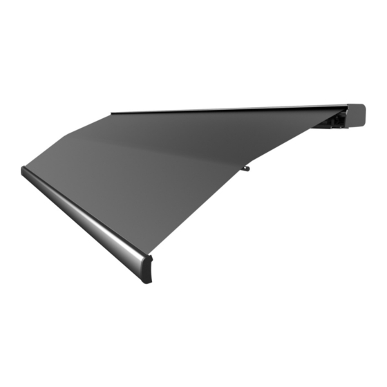
BASIC SYSTEM OVERVIEW The VISION Awning consists of three main components: 1. Mechanical system – consisting of: • The enclosure (or cassette) protects the awning while closed. • The roller tube which is mounted within the cassette. • The top cover or fabric rolled onto the roller tube and connected to the lead rail that extends from the enclosure when the awning is opened. -
Page 5: Installation Instructions
INSTALLATION INSTRUCTIONS FOR PERSONAL SAFETY AND QUALITY OF INSTALLATION, A MINIMUM OF TWO INSTALLERS IS RECOMMENDED FOR THIS PRODUCT. Before beginning to install the awning please verify the following; • The vehicle is parked and leveled on suitable hard standing. •... -
Page 6: Product Description
PRODUCT DESCRIPTION The VISION is a dual pitch awning system provides protection from the sun at a touch of a button. The VISION awning is built to your specifications with the highest quality materials available, your unit features: • A standard motor that operates with a wireless motor controller or a wireless motor that operates with an integrated motor control. -
Page 7: Unpacking
A. UNPACKING Before starting any of the installation procedures: 1. Unpack the awning and inspect the product for any possible damage that may have occurred during shipping. 2. Ensure that the length and motor placement of your awning are correct. 3. -
Page 8: Layout And Mounting The Brackets
B. LAYOUT AND MOUNTING THE BRACKETS 1. MOUNTING THE AWNING – NOTE: The clearances needed for mounting the VISION varies by manufacturer. The shape of the roof, the depth of installation and all other factors should be taken into consideration when installing this product. -
Page 10: Mounting The Awning
C. MOUNTING THE AWNING 1. Lift the awning into position for fastening to the mounting brackets. a. Ladders are usually sufficient however a scaffold or forklift may be used. b. If using a forklift use all necessary caution to protect the surface of the awning. -
Page 11: Motion Sensor
D. MOTION SENSOR NOTE: The Motion Sensor requires a hard wired 12V. D.C. connection. 12v DC MOTION SENSOR (Hard wired) The Motion Sensor will come from the factory pre-programmed. A hole may need to be drilled for the power cable. 1. -
Page 12: Testing And Adjustments
AWNING IS CLOSED. THIS WILL SIGNIFICANTLY REDUCE THE LIFE OF THE MOTOR. 1. The AC motors used in Girard Systems awnings are reversible. Any reference made to the motor limit switches in these instructions is based on the right-hand placement of the motor. For left hand placement, simply reverse the instructions. - Page 13 4. Extend the awning a few feet to gain access to the motor. Locate the motor (standard installation is on the right hand side of the awning). The limit adjustment pots are located on the head of the motor. Using the symbols printed next to the adjustment pots, turn the black key (or 4mm Allen wrench) to make the necessary adjustments.
-
Page 14: Adjusting Pitch
B. ADJUSTING PITCH NOTE: This adjustment is usually required after an arm replacement. Also, if the elbow of the arm hits the bottom of the casing as the lead rail closes. Tools Required • 19mm (3/4”) open-end wrench ADJUST LOCK (Figure 6) 1. -
Page 15: Testing The Motion Sensor
TESTING THE MOTION SENSOR 1. Partially extend the awning. 2. Physically activate the Motion sensor by pulling down the corner of the lead rail about 12” and then release. This should create enough movement to activate the motion sensor. 3. At this point the awning should retract; if not, check the electrical connections to the selected power source. -
Page 16: Troubleshooting Guide
TROUBLESHOOTING GUIDE PROBLEM: The lead rail is binding on the side of the awning casing; i.e. the rail is offset from housing. SOLUTION: • Open the awning about 3 feet. • Loosen the lead rail adjustment screws on all arms. •... - Page 17 • Check that the motor’s thermal protection circuit breaker has not tripped. The 110V AC motor supplied in your VISION Awning is designed for intermittent use and may cut out temporarily if it has overheated. When this occurs you must...
- Page 18 You may use a manual crank during this period. • If this does not solve the issue please call the Girard Systems service line at (949)259-4000 or toll free at (800)382-8442.
-
Page 20: Component Identification
VISION 22’ FABRIC GUIDE SUPPORT 7010022-10 VISION COVER PLATE ASSEMBLY LH 701L004-11 VISION LOCK PLATE ASSEMBLY LH 701L005-12 VISION ROLLER TUBE SUPPORT BRACKET ASEMBLY (2) 7010006-13 VISION GUDGEON BUSHING 7010007-14 VISION PLASTIC GUDGEON WASHER 7010008-15 VISION MAIN HOUSING GUIDE ASSEMBLY (2) - Page 21 VISION 18’ LEAD RAIL 7010018-44 VISION 22’ LEAD RAIL 7010022-44 VISION LEAD RAILEND CAP ASSEMBLY RH 701R026-45 VISION LEAD RAIL ARM SUPPORT (2 or 3) 7010027-49 NOTE: WHEN QUOTING/WRITING PART NUMBERS ADD A “B” OR “W” ON THE END FOR COLOR WHERE REQUIRED.
Need help?
Do you have a question about the VISION and is the answer not in the manual?
Questions and answers