Table of Contents
Advertisement
Quick Links
Advertisement
Table of Contents

Subscribe to Our Youtube Channel
Related Manuals for ipf electronic PY740025

Summary of Contents for ipf electronic PY740025
- Page 1 Manual for PY740025/26...
-
Page 2: Table Of Contents
MANUAL [PY740025/26] • Subject to alteration! Version: 22.10.2018 Contents General information ........................3 Concerning the contents of this document ..................3 Intended use ........................... 3 Safety warnings ..........................3 Commissioning ..........................4 Connection ............................ 8 Connection cable ..........................8 Pin assignment and connection diagram ..................9 Installation ........................... -
Page 3: General Information
General information 1.1 Concerning the contents of this document This manual contains information about the installation and initial setup of the ipf PY740025 and PY740026 light section sensors. It is a supplement to the mounting instructions supplied with each sensor. -
Page 4: Commissioning
MANUAL [PY740025/26] • Subject to alteration! Version: 22.10.2018 Commissioning After the sensor is connected and installed, configure it via the display. The sensor is then ready for operation and outputs the measuring value in mm to the screen. Optionally, the measuring field can be limited or the switching output can be configured. - Page 5 MANUAL [PY740025/26] • Subject to alteration! Version: 22.10.2018 Installation Function HEIGHT At the function HEIGHT, the reference surface will be teached-in with FLEX MOUNT. The sensor can be mounted angled with up to +/- 30° to the reference surface. Left Right +/-30°...
- Page 6 MANUAL [PY740025/26] • Subject to alteration! Version: 22.10.2018 Application specific settings HEIGHT Height of an object For a height measurement, the required MEAS TYPE (average value, maximum, minimum or delta). The reference surface (0) is the maximum measuring range of the sensor, or if present, the FLEX MOUNT teached reference surface.
- Page 7 MANUAL [PY740025/26] • Subject to alteration! Version: 22.10.2018 Optional settings FLEX MOUNT If the sensor is mounted at an angle or the reference surface is not at the End of the measuring range Sde, FLEX MOUNT must be activated and the reference surface taught in.
-
Page 8: Connection
MANUAL [PY740025/26] • Subject to alteration! Version: 22.10.2018 Connection ATTENTION! Incorrect supply voltage will destroy the device! ATTENTION! Connection, installation and commissioning may only be performed by qualified personnel. ATTENTION! The IP protection class is valid only if all connections are connected as described in the technical documentation. -
Page 9: Pin Assignment And Connection Diagram
MANUAL [PY740025/26] • Subject to alteration! Version: 22.10.2018 3.2 Pin assignment and connection diagram Color Function Description Pin 1 WH = white n.c. Not connected Pin 2 BN = brown + Vs Voltage supply (+15…+28 VDC) Pin 3 GN = green analog Analog output (4…20 mA or 0…10V) -
Page 10: Installation
MANUAL [PY740025/26] • Subject to alteration! Version: 22.10.2018 Installation ATTENTION! Connection, installation and commissioning may only be performed by qualified personnel. Protect optical surfaces from moisture and dirt. 4.1 Mounting The sensor has four mounting holes for flexible alignment and mounting. The use of 2 M4x35 screws is recommended for mounting. -
Page 11: The Reference Surface
MANUAL [PY740025/26] • Subject to alteration! Version: 22.10.2018 4.3 The reference surface If the height of the object is to be measured from a specific surface or the sensor is mounted at an angle up to ±30°, then the reference surface must be taught in with the FLEX MOUNT function. -
Page 12: Measuring Field Defintion
MANUAL [PY740025/26] • Subject to alteration! Version: 22.10.2018 4.4 Measuring field defintion The maximum measuring field and additional important measuring field definitions are described in the following diagram. The important terms "left" and "right" are to be regarded respectively from the viewpoint of the connector side of the sensor. - Page 13 MANUAL [PY740025/26] • Subject to alteration! Version: 22.10.2018 4.4.1 Blind region The region from sensor level R2 up to the start of measuring range Sdc is called the blind region, i.e. the sensor cannot detect any objects there. Objects in this area can cause incorrect measuring values.
-
Page 14: Mounting
MANUAL [PY740025/26] • Subject to alteration! Version: 22.10.2018 4.5 Mounting The sensor can be installed at an inclination of up to ±30° to the reference surface. This is particularly useful when space conditions do not allow any other installation option. See chapter FLEX MOUNT. - Page 15 MANUAL [PY740025/26] • Subject to alteration! Version: 22.10.2018 4.5.2 Practical zero point search The LIVE MONITOR mode can be used to find the LEFT EDGE reference point (0 mm). This function displays the Right Left RISING LEFT EDGE RISING (the first rising edge from the left side) of objects.
-
Page 16: Installation Accessories
MANUAL [PY740025/26] • Subject to alteration! Version: 22.10.2018 4.6 Installation accessories To ensure optimal mounting, the mounting bracket AP000043 is available as an accessory. This bracket fits best with the ball-head holder AY000143. The sensor can be aligned within the entire pivoting radius of the ball-head. -
Page 17: Configuration
MANUAL [PY740025/26] • Subject to alteration! Version: 22.10.2018 Configuration 5.1 Overview of control elements LEDs Graphical Avg HEIGHT 112.4 mm Touch panel: Four touch-sensitive keys DOWN 5.1.1 Anzeigemodi des Displays Run mode 112.42 mm The sensor is in run mode, the measuring value is displayed in large characters. - Page 18 MANUAL [PY740025/26] • Subject to alteration! Version: 22.10.2018 5.1.2 Functions of the individual keys Pressed briefly Pressed >2 s. Back Jump to Run mode Up/increase value DOWN Down/decrease value Save new value* * Only in the setting menu when the top line is displayed on a black background (change value) 5.1.3...
- Page 19 MANUAL [PY740025/26] • Subject to alteration! Version: 22.10.2018 5.1.4 Further key functions Action Reaction Unlock locked touch panel Slide over all keys from left to right Only if touch panel is locked Jump directly to run mode Slide over all keys from right to left Can be used from any menu 5.1.5...
-
Page 20: Function Tree
MANUAL [PY740025/26] • Subject to alteration! Version: 22.10.2018 5.2 Function tree The menu that can be accessed via the touch panel is shown below. www.ipf.de • Kalver Straße 25 - 27 • 58515 Lüdenscheid Tel +49 2351 9365-0 • Fax +49 2351 9365-19 info@ipf.de •... -
Page 21: Live Monitor
MANUAL [PY740025/26] • Subject to alteration! Version: 22.10.2018 5.3 LIVE MONITOR The installation conditions can be checked using LIVE MONITOR. The sensor outputs the angle and edge position to the object with the smallest distance to the sensor. LIVE MONITOR 15,7°... - Page 22 MANUAL [PY740025/26] • Subject to alteration! Version: 22.10.2018 “End of measuring range” of the sensor represents the standard reference for angle measurement. • Once the reference surface with FLEX MOUNT is teached, “End of measuring range” is no longer valid. The new reference surface corresponds to 0° tilt angle.
- Page 23 MANUAL [PY740025/26] • Subject to alteration! Version: 22.10.2018 Displaying the tilt angle to the reference surface For displaying the tilt angle of the sensor to the reference surface, FLEX MOUNT must not be activated and in the measuring field must not be an object. The output will be ---- for EDGE LEFT RISING of the object.
-
Page 24: Messtyp
MANUAL [PY740025/26] • Subject to alteration! Version: 22.10.2018 5.4 MESSTYP The PY740025/26 can determine the height of an object in various ways. The measuring value is calculated in mm with analog output. NOTE If the MEAS TYPE is changed, SCALE OUT, DIGITAL OUT, FLEX MOUNT and FIELD OF VIEW are reset to the default setting. -
Page 25: Flex Mount (Function Height)
MANUAL [PY740025/26] • Subject to alteration! Version: 22.10.2018 5.5 FLEX MOUNT (Function HEIGHT) With FLEX¨MOUNT the reference surface will be teached-in. With respect of its inclination, the sensor is able to calculate the height of objects correctly. This function is recommended for the correct calculation of the height of objects with respect to the reference surface. - Page 26 MANUAL [PY740025/26] • Subject to alteration! Version: 22.10.2018 5.5.1 The FLEX MOUNT function is switched off by "No", the sensor can be mounted again at a right angle. If FLEX MOUNT is not activated, a 0° angle and "distance" = end of measuring range Sde are set.
- Page 27 MANUAL [PY740025/26] • Subject to alteration! Version: 22.10.2018 5.5.3 TEACH REF Conditions during TEACH REF The following four conditions must be met during the reference surface teach-in process. If one of the symbols listed below appears on the display, it lights up red. The teaching process can only begin after elimination of all errors (the display no longer lights up red).
- Page 28 MANUAL [PY740025/26] • Subject to alteration! Version: 22.10.2018 5.5.4 CORRECTION The reference surface can be moved in height with CORRECTION after teaching. This is useful when using an auxiliary plate, or if the reference surface has to be hidden. Using an auxiliary plate In this menu item, the reference surface is defined with due regard to the thickness of the auxiliary plate (optional).
- Page 29 MANUAL [PY740025/26] • Subject to alteration! Version: 22.10.2018 Hide the reference surface The fact that everything is hidden below the reference surface, the originally teached-in reference surface can be hidden by shifting the reference surface upwards. New position of the reference surface. Everything underneath is hidden.
-
Page 30: Object
MANUAL [PY740025/26] • Subject to alteration! Version: 22.10.2018 5.6 OBJECT To improve sensitivity to dark objects, the exposure time can be increased. This also changes the measuring repetition time. 5.6.1 Object: Bright (Reflectivity > 18%, white-gray) Exposure time (Pulse Short duration) 5.6.2... - Page 31 MANUAL [PY740025/26] • Subject to alteration! Version: 22.10.2018 The diagram shows the effects of the median (sample size 5). The filter is used to suppress errors. The output changes after a defined number of samples (sample size/2). The measurement frequency is not affected by this filter, but rather the response time.
- Page 32 MANUAL [PY740025/26] • Subject to alteration! Version: 22.10.2018 Number of samples until the correct value will be output: In PRECISION mode HIGH, the distance has to be stable for 4 + 16 samples for the output to show the current value.
-
Page 33: Field Of View
MANUAL [PY740025/26] • Subject to alteration! Version: 22.10.2018 5.8 FIELD OF VIEW The width of the measuring field can be limited with the FIELD OF VIEW function. All measuring values outside the set measuring field are ignored. This is particularly useful if, for example, the measuring field contains an unwanted object that should not be detected. - Page 34 MANUAL [PY740025/26] • Subject to alteration! Version: 22.10.2018 5.8.2 LIMIT LEFT Limitation of the left side of the measuring field in mm, measured from the reference point. 5.8.3 LIMIT RIGHT Limitation of the right side of the measuring field in mm, measured from the reference point.
-
Page 35: Analog Out
MANUAL [PY740025/26] • Subject to alteration! Version: 22.10.2018 5.9 ANALOG OUT 5.9.1 SCALE OUT In the factory setting, the analog output runs across the entire measuring range (start of measuring range Sdc - end of measuring range Sde) from 0...10V (voltage mode) or from 4...20mA (current mode). - Page 36 MANUAL [PY740025/26] • Subject to alteration! Version: 22.10.2018 Example: SCALE OUT with HEIGHT function At an object height of 30 mm, the sensor should display 20 mA and 4 mA at a height of 5 mm. Set OFFSET to 5 mm •...
-
Page 37: Digital Out
MANUAL [PY740025/26] • Subject to alteration! Version: 22.10.2018 5.10 DIGITAL OUT With Pin 4 (out), the user has a configurable switching output. It can be defined as a single switching point (threshold) or a window. Pin 4 is activated when the value (point or window) is exceeded or not reached (active high or active low depending on the setting). - Page 38 MANUAL [PY740025/26] • Subject to alteration! Version: 22.10.2018 5.10.3 WINDOW P1 Window point 1 (for the WINDOW mode) is selected in mm using the arrow keys. The point must lie within the measuring range (greater than start of measuring range Sdc +2x hysteresis 5.10.4 WINDOW P2...
-
Page 39: System
MANUAL [PY740025/26] • Subject to alteration! Version: 22.10.2018 5.11 SYSTEM 5.11.1 ANALOG OUT The analog output can be reset to voltage or current, depending on purpose. See the Section "Interfaces and output --> Analog signal output". Current • • Voltage 5.11.2 DISPLAY LIGHT... - Page 40 MANUAL [PY740025/26] • Subject to alteration! Version: 22.10.2018 5.11.5 RESET This resets all settings in sensor parameters to the factory settings. MEAS TYPE = Delta HEIGHT OBJECT = Bright PRECISION = Standard SCALE OUT = Max. values FLEX MOUNT = Not activated (standard installation) FIELD OF VIEW = Max.
-
Page 41: Setting
MANUAL [PY740025/26] • Subject to alteration! Version: 22.10.2018 5.12 SETTING The settings entered in the sensor can be applied, stored or displayed here. 5.12.1 APPLY The settings saved under SAVE can be activated here. • Setting 1 Setting 2 •... -
Page 42: Function And Definition
MANUAL [PY740025/26] • Subject to alteration! Version: 22.10.2018 Function and definition 6.1 Sensors data sheet General data PY740025 PY740026 Function Object height Object height Function: FLEX MOUNT Function: FIELD OF VIEW Measuring range (distance) 100…150 mm 100…500 mm Start of measuring range Sdc... - Page 43 MANUAL [PY740025/26] • Subject to alteration! Version: 22.10.2018 Min. reference surface length 24 mm 12 mm LIVE MONITOR: Minimum object height 4 mm 10 mm Minimum object width 4 mm 12 mm Digital output hysteresis 0.5% of Sd (switch point)
- Page 44 MANUAL [PY740025/26] • Subject to alteration! Version: 22.10.2018 Operational mode pulsed pulsed Pulse duration bright mode 0.6 ms 0.15 ms dark mode 1.8 ms 0.8 ms Pulse period bright mode >1.7 ms >0.65 ms dark mode >2.9 ms >1.3 ms...
- Page 45 MANUAL [PY740025/26] • Subject to alteration! Version: 22.10.2018 ∥ Parallel plane: δ www.ipf.de • Kalver Straße 25 - 27 • 58515 Lüdenscheid Tel +49 2351 9365-0 • Fax +49 2351 9365-19 info@ipf.de • ipf electronic gmbh │ │...
- Page 46 MANUAL [PY740025/26] • Subject to alteration! Version: 22.10.2018 6.1.2 Dimensions *Optical axis www.ipf.de • Kalver Straße 25 - 27 • 58515 Lüdenscheid Tel +49 2351 9365-0 • Fax +49 2351 9365-19 info@ipf.de • ipf electronic gmbh │ │...
-
Page 47: Functional Principle
MANUAL [PY740025/26] • Subject to alteration! Version: 22.10.2018 6.2 Functional principle The sensor works on the laser triangulation principle. By means of special optics, a laser beam is enlarged into a line and projected to the surface of the object to be measured. Using the multi-lens system, the reflected light from this laser line is projected onto a matrix. - Page 48 MANUAL [PY740025/26] • Subject to alteration! Version: 22.10.2018 6.2.1 qTarget The measuring field is aligned with the housing reference surfaces at the factory. The beam position in every sensor is in exactly the same spot, which makes planning and sensor replacement very easy.
-
Page 49: Measuring Repetition Time And Response Time
MANUAL [PY740025/26] • Subject to alteration! Version: 22.10.2018 6.3 Measuring repetition time and response time Response time fast Measuring 2x measuring repetition time repetition time Laser- exposure Response time worst case 3x measuring repetition time 6.3.1 Measuring repetition time The measuring repetition time (specified in milliseconds) is the time between two exposure times. -
Page 50: Hysteresis
MANUAL [PY740025/26] • Subject to alteration! Version: 22.10.2018 6.4 Hysteresis 6.4.1 Definition of the hysteresis sensing distance ��������. Without hysteresis ����, objects could at the limit of the switching points lead to ceaseless The Hysteresis is the difference between switch-on and switch-off point. It is defined as a percentage of the on/off switching or bouncing. - Page 51 MANUAL [PY740025/26] • Subject to alteration! Version: 22.10.2018 6.4.3 Characteristics of the switching output at SWITCH POINT Measuring value Hysteresis SWITCH POINT High Output level 6.4.4 Characteristics of the switching output at WINDOW Measuring value Hysteresis WINDOW P2 WINDOW WINDOW P1...
-
Page 52: Object To Be Measured
MANUAL [PY740025/26] • Subject to alteration! Version: 22.10.2018 6.5 Object to be measured 6.5.1 Smallest detectable object For an object to be reliably detected, it must conform to the minimum object width . This minimum object width varies with the distance from the sensor. -
Page 53: Interfaces And Outputs
MANUAL [PY740025/26] • Subject to alteration! Version: 22.10.2018 6.6 Interfaces and outputs All sensor inputs and outputs that transmit measuring data are referred to as interfaces. Analog current output Synchronization Switching output Alarm output NOTE When an object moves laterally out of the measuring field, the last valid output value is retained until an object is again present in the measuring range. - Page 54 MANUAL [PY740025/26] • Subject to alteration! Version: 22.10.2018 Formulas for analog signal conversion The measuring values can be converted from mm into the analog output signal and vice versa with the following formulas. If the measuring range has been limited with SCALE OUT, the new settings for Current Start of measuring range Sdc and Current End of measuring range Sde must be used.
- Page 55 MANUAL [PY740025/26] • Subject to alteration! Version: 22.10.2018 6.5.5 Sync-In / Trigger The measurement and signal output can be interrupted with the Sync-In input by connecting with high. As long as Sync-In stands at high, the sensor delays the next measurement (Hold) and reduces the power of the laser beam.
- Page 56 MANUAL [PY740025/26] • Subject to alteration! Version: 22.10.2018 Measuring if Synch-In low: The sensor checks the level of the Sync-In each time before it sends out the laser pulse. If it is low, the sensor will immediately begin the next measurement.
- Page 57 MANUAL [PY740025/26] • Subject to alteration! Version: 22.10.2018 Sync-In Low to High: If the Synch-In level is High, the sensor completes the actual measurement, but do not start the next measurement. All outputs are held (Hold function). High Sync High...
- Page 58 MANUAL [PY740025/26] • Subject to alteration! Version: 22.10.2018 Sync-In High to Low: Sync-In has to set from High to Low to bring the sensor back into the measuring mode. The Sync-In must be at least 5μs set to low level, so that the sensor starts to measure. For this first measuring cycle, the response time will be 5μs longer.
- Page 59 MANUAL [PY740025/26] • Subject to alteration! Version: 22.10.2018 6.5.6 Switching output The switching output can be set as a point or a window, see Section DIGITAL OUT. The output is transmitted as a push-pool signal with active high or active low (inverted), depending on the setting.
- Page 60 MANUAL [PY740025/26] • Subject to alteration! Version: 22.10.2018 6.5.8 Response of outputs If no object is within the measurement range, the sensor will hold the last valid signal. The alarm output is high during this time. Object Measuring range Object...
-
Page 61: Touch Panel
MANUAL [PY740025/26] • Subject to alteration! Version: 22.10.2018 6.6 Touch panel 6.6.1 Function and design The display consists of a monochrome 128 x 32 pixel LCD with RGB LED background illumination. The sensor can be configured using four capacitive touch operator interfaces. -
Page 62: Standard Deviation
MANUAL [PY740025/26] • Subject to alteration! Version: 22.10.2018 Standard deviation The standard deviation is a term from the field of statistics or stochastics and is given in σ (sigma). With the standard deviation it is possible to determine how great the dispersion of values around a mean value is. -
Page 63: Safety Instructions And Maintenance
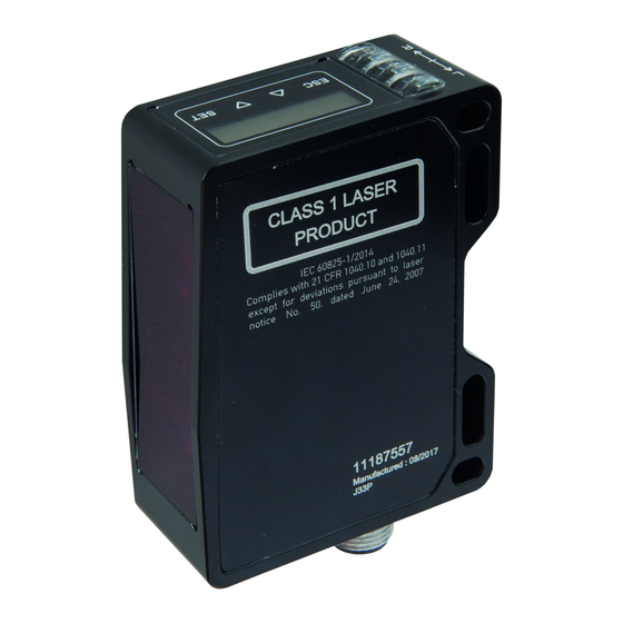
MANUAL [PY740025/26] • Subject to alteration! Version: 22.10.2018 Safety instructions and maintenance 7.1 General safety instructions Intended use This product is a precision device and is used for object detection and the preparation and/or provision of measuring values as electrical quantities for a subsequent system. Unless this product is specially labeled, it may not be used for operation in potentially explosive environments. - Page 64 MANUAL [PY740025/26] • Subject to alteration! Version: 22.10.2018 Class 2: Do not stare into beam Class 1: No risk to eyes or skin Class 2 lasers emit radiation in the visible portion of A Class 1 laser product is defined as safe the spectrum (400 nm to 700 nm).
-
Page 65: Influence Of Ambient Light
MANUAL [PY740025/26] • Subject to alteration! Version: 22.10.2018 7.3 Influence of ambient light Ambient light from lamps, the sun, etc. in the view field of the sensor can lead to malfunctions or a reduction of accuracy and should be avoided as much as possible. -
Page 66: Error Correction And Tips
MANUAL [PY740025/26] • Subject to alteration! Version: 22.10.2018 Error correction and tips 8.1 Examples of sensor setup 8.1.1 Analog height measurement with inclined installation of 30°, height 10 mm= 0V, height 30 mm = 10 V 1. Connection: In accordance with connection diagram 2. -
Page 67: Error Correction
MANUAL [PY740025/26] • Subject to alteration! Version: 22.10.2018 8.2 Error correction Error Error correction No function • Check connection. Power supply 15…28 VDC between pin 2 (+Vs, brown) and pin 7 (GND, blue) Green LED flashes • Short circuit at the digital output. Check connection.
Need help?
Do you have a question about the PY740025 and is the answer not in the manual?
Questions and answers