
Related Manuals for GF Health Products Hausted Horizon Series


Summary of Contents for GF Health Products Hausted Horizon Series
- Page 1 Operating Manual Hausted Horizon Series ® X-ray trauma Stretcher Model: 468Xry GFH1300087RevB15 GF HEALTH PRODUCTS, INC.
- Page 2 WARNING - COPYING PROHIBITED this manual is protected by Federal Copyright law, which provides for damages of up to uSD $20000, as well as criminal fines and imprisonment, for unauthorized copying.
- Page 3 GF Health Products, Inc. for replace- ment copies, with serial and model number of the unit. GF Health Products, Inc. carries a complete line of accessories for use with this stretcher. a representative will gladly review these with you.
- Page 4 Manufactured by: GF Health Products, Inc. 336 Trowbridge Drive Fond du Lac, WI 54937 770.368-4700 Main 770.368.2386 Fax www.Hausted.com equipment not suitable for use in the presence of a flammable anesthetic mixture with air or oxygen or nitrous oxide. the base language of this document is engliSH.
-
Page 5: Table Of Contents
taBle OF COntentS 1 listing of warnings and Cautions ........................ 2 uncrating instructions ............................3 Operating instructions ............................3.1 Stretcher Features ................................3-1 3.2 Stretcher Specifications .............................3-3 3.3 Braking and Steering Operation ..........................3-4 3.3.1 applying the Brakes ..............................3-4 3.3.2 releasing the Brakes ...............................3-4 3.3.3 applying the Steering lock/Fifth wheel ......................3-4 3.3.4 releasing the Steering lock/Fifth wheel ......................3-4 3.4 litter top Height adjustment ...........................3-5... - Page 6 TABLE OF CONTENTS 3.10 Loading the Built-In Grid Holder........................3-14 3.11 Loading Cassettes Laterally ..........................3-15 3.11.1 Lower the Retracto Rails on Stretcher ......................3-15 3.12 Using Carrier Offset Positions ..........................3-16 3.12.1 End label Markings ............................. 3-16 3.12.2 Placing Carrier in Offset position ........................3-16 4 Troubleshooting Guide ............................
-
Page 7: Listing Of Warnings And Cautions
LISTING OF WARNINGS AND CAUTIONS The following Safety Precautions must be Be sure rails are locked before leaving patient. observed when operating or servicing this Hausted® Do not sit on end – tipping may occur. Horizon Model 468XRY X-Ray and Trauma Stretcher. WARNING indicates the potential for personal injury and CAUTION Indicates a potentially hazardous situation WARNING –... -
Page 8: Uncrating Instructions
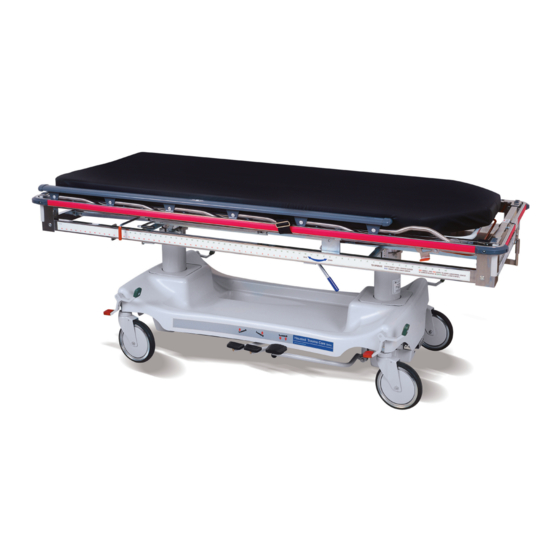
If any features of the equipment do not work properly, bands are cut and tension is released. call GF Health Products, Inc. at 770.368.4700. 5. Clean the equipment using mild detergent to remove any dirt accumulated during shipment, and place the equipment into service. - Page 9 OPERATING INSTRUCTIONS 3.1 STRETCHER FEATURES Three Position Patient Side Rails Built-in Chest X-ray Cassette Positioning System See Warnings C & D & Caution F 3" Pad Standard Pneumatic Fowler Backrest Radiolucent Litter Top Built-in IV and Accessory Patient Surface Wells on all Four Corners Full Perimeter Protective Bumper...
-
Page 10: Operating Instructions
Operating inStruCtiOnS 3.1 StretCHer FeatureS warningS– CautiOnS anD prOper OperatiOn: Do not sit on end – tipping may occur. a. the stretchers have a warning label located at the foot end stating: maximum patient- weight 226 Kilograms (500 lbs.) B. patient entry, egress and transfer should always be done with the brakes locked. -
Page 11: Stretcher Specifications
Maximum patient weight 226 Kilograms (500 lbs) Between Rails 28.50 ll dimension are ±.375 inches. Patient Surface GF Health Products, Inc. reserves the right to change speci cations without notice. Stretcher Weight: 315 lbs. 64.00 Rail Length 3.00 Pad Standard 0-90°... -
Page 12: Braking And Steering Operation
Operating inStruCtiOnS 3.3 BraKing anD Steering OperatiOn 3.3.1 applying the Brakes the four-wheel central braking system is activated by depressing the red pedal at any of the four corners of the unit (Figure 3-1). to fully engage the brakes, the pedal should be pressed approximately 45°. -
Page 13: Litter Top Height Adjustment
Operating inStruCtiOnS 3.4 litter tOp HeigHt aDJuStMent 3.4.1 Height adjustment press the pump pedal to the floor (Figure 3-4), then release. repeat this process until the desired height is obtained. use smooth strokes on pump pedal to ensure patient comfort. Figure 3 - 4 3.4.2 lowering the litter top press down on the two release pedals at... -
Page 14: Retracto Rail Operation
OPERATING INSTRUCTIONS 3.5 RETRACTO RAIL OPERATION CAUTION: ALWAYS BE SURE RAIL IS LOCKED INTO POSITION BEFORE LEAVING THE PATIENT UNATTENDED. 3.5.1 Raising the Rail FIGURE 3-8A Grasp rail top cap in the middle of the rail (Figure 3-8A) and lift. 3.5.2 Placing the Rail at Half Height Grasp the rail (Figure 3-8A) and lift up on the red trigger under the litter top (Figure... -
Page 15: Fowler Backrest Operation
Operating inStruCtiOnS 3.6 FOwler BaCKreSt OperatiOn 3.6.1 raising the Backrest grasp the fowler backrest tube and the gas spring activating handle (Figure 3-10), squeeze the handle and the tube together and lift. Once the desired incline is achieved, release the handle. (amount of manual lifting required Figure 3 - 10 will vary depending on patient size;... -
Page 16: Chest X-Ray Cassette System Operation
Operating inStruCtiOnS 3.7 CHeSt X - ray CaSSette SySteM OperatiOn 3.7.1 loading Cassettes raise the fowler to 90°. rotate the red angles out until they are 90° to the tube (Figures 3-12 & 3-13). insert the cassette between fowler angles (Figure 3-14). Support the cassette while rotating the pressure rods out (Figure 3-15), until they are pressing on the cassette Figure 3 - 12... -
Page 17: Loading The Cassette Carrier
Operating inStruCtiOnS 3.8 lOaDing tHe CaSSette Carrier nOte: the following instructions can be done from either side of the unit. 3.8.1 placing Carrier in loading position Before attempting to access the carrier, you must first place it in the proper position for loading. -
Page 18: Loading And Centering Cassette In Carrier
Operating inStruCtiOnS 3.8 lOaDing tHe CaSSette Carrier 3.8.3 loading and Centering Cassette in Carrier with the tray exposed, place the cassette between the two angles built into the carrier (Figure 3-26). Once the cassette is in the tray, push the angle up against the side of the Figure 3 - 26 cassette (Figure 3-27). -
Page 19: Positioning The Cassette Carrier
Operating inStruCtiOnS 3.9 pOSitiOning tHe CaSSette Carrier 3.9.1 proper usage of Side label Markings running along both sides of the stretcher on the lower tubes is a label that is used to assist in defining accurate location of the center point of the cassette along the longitudinal axis of the stretcher. the upper set of (green) numbers define the approximate center point that the X-ray will be taken on the stretcher (Figure 3-30). - Page 20 Operating inStruCtiOnS 3.9 pOSitiOning tHe CaSSette Carrier Figure 3 - 32 Figure 3 - 33 Figure 3 - 34 Simulated Center of X-ray Figure 3 - 35 3-12 GFH1300087RevB15...
-
Page 21: Adjust The Carrier Location
Operating inStruCtiOnS 3.9 pOSitiOning tHe CaSSette Carrier 3.9.2 adjust the Carrier location Determine the required location of the cassette carrier (See “proper usage of Side label Markings” on Section 3.9.1). grasp the red handle (Figure 3-36) and rotate it slightly toward the head end of the stretcher (Figure Figure 3 - 36 3-37). -
Page 22: Loading The Built-In Grid Holder
Operating inStruCtiOnS 3.10 lOaDing tHe Built - in griD HOlDer 3.10.1 loading the Built-in grid Holder position the carrier all the way toward the head end (see “adjusting the Carrier loca- tion,” above). raise the fowler backrest to an upright position (Figure 3-41), exposing the carrier. - Page 23 Operating inStruCtiOnS 3.11 lOaDing CaSSette laterally 3.11.1 adjust the Carrier location Slide one corner of the cassette between the gray rail cap and the pad (Figure 3-44). Continue inserting cassette until it is securely captured between rail and pad (Figure 3-45). Once in place the cassette can be slid up Figure 3 - 44 and down the length of the top as required...
-
Page 24: Using Carrier Offset Positions
Operating inStruCtiOnS 3.12 uSing Carrier OFFSet pOSitiOnS 3.12.1 end label Markings On both ends of the stretcher, on the lower tube, there is a label that will be used in defining the different “offset” positions that the carrier can be set to. in Figure 3-47, the foot end of the stretcher is shown as well as the positions. -
Page 25: Troubleshooting Guide
GF Health Products, Inc. Carrier will not pull out when Step 1. Make sure carrier is in proper position for loading or using offset pulling on black handle. - Page 26 Step 1. there are no customer serviceable items- call for service. does not operate properly or is broken. For service, please contact GF Health Products, Inc. at 770.368.4700. (please be sure to have stretcher model and serial number available.) GFH1300087RevB15...
-
Page 27: Preventive Maintenance For The User
NOTE: For more detailed information, please contact GF Health Products, Inc. at 770.368.4700. NOTE: In addition to the User Preventive Maintenance, a more detailed Preventive Maintenance Program is also required to keep the equipment in good working order. - Page 28 preVentiVe MaintenanCe FOR THE USER 5.1 luBriCatiOn guiDe piVOt pOintS On CHeSt piVOt pOintS On Centering CaSSette angleS anD angle linKS – unDer tray preSSure rODS (Only One SHOwn) piVOt pOintS On FOwler nO luBriCatiOn iS aCtiVating HanDle anD neeDeD On tHe BlaCK gaS Sping MOunting plaStiC BarS pOint (BOtH SiDeS)
-
Page 29: Recommended Optional Accessories
Bumpers and pin Striping for Department identification it is recommended that only accessories approved by GF Health Products, Inc. be used with this device. to order accessories, or for more detailed information on accessories, please contact GF Health Products, Inc. at 770.368.4700. GFH1300087RevB15... -
Page 30: Recommended Replacement Parts
reCOMMenDeD replaCeMent partS Figure 4 - 1 grid Holder Cassette Carrier uSe StanDarD pVC CeMent tO inStall nOte: use instant adhesive when installing any vinyl or rubber cap. use pVC cement to install item 20. Figure 4 - 1 GFH1300087RevB15... - Page 31 reCOMMenDeD replaCeMent partS Figure 7 - 1. BaSe aSSeMBly item no. part no. C Description units per assembly 066508 aSSeMBly, Brake pedal, right 066507 aSSeMBly, Brake pedal, left 066544 Cap, Brake pedal, green 066543 Cap, Brake pedal, red 069459 riVet, Brake pedal Cap 068343 paD, pump pedal 061164...
- Page 32 reCOMMenDeD replaCeMent partS Figure 4 - 2 Figure 4 - 2 GFH1300087RevB15...
- Page 33 reCOMMenDeD replaCeMent partS Figure 4 - 2 item no. part no. C Description units per assembly 076295 laBel, left Side X-ray unit 076296 laBel, right Side X-ray unit 076298 laBel, Foot end X-ray 076297 laBel, Head end X-ray 076306 laBel, Head end Bumper 076307 laBel, Foot end Bumper 076303...
- Page 34 reCOMMenDeD replaCeMent partS Figure 4 - 3 For Service Call 770.368.4700 Figure 4 - 3 GFH1300087RevB15...
- Page 35 reCOMMenDeD replaCeMent partS Figure 4 - 3 item no. part no. C Description units per assembly 075840 laBel, trauma Care, right 075831 laBel, Base end 075841 laBel, trauma Care, left 031457 laBel, universal Serial number 063022 laBel, Service 031458 laBel, Overlay, Clear Vinyl GFH1300087RevB15...
-
Page 36: Warranty
SCOPE OF WARRANTY GF Health Products, Inc. (“GF”) warrants to the original purchaser only that it will replace or repair components, at GF’s sole discretion, that are defective in material or workmanship under normal use and service. All warranties are conditioned upon the proper use of the products strictly in accordance with good commercial practice and applicable GF instructions and manuals, including proper use and maintenance. - Page 38 www.hausted.com www.grahamfield.com...
Need help?
Do you have a question about the Hausted Horizon Series and is the answer not in the manual?
Questions and answers