Table of Contents
Advertisement
SAFETY ..................................................................... 4
Introduction ................................................................ 4
PRODUCT PRESENTATION .................................... 5
INSTALLATION .......................................................... 7
Unpacking .................................................................. 7
Voltage-range selection ............................................. 7
Grounding .................................................................. 8
Connecting external reference ................................... 8
Installing options ........................................................ 8
Calibrating the MTCXO.............................................. 8
OPERATING INSTRUCTIONS ................................ 10
Using the Timer/counter........................................... 10
Battery unit .............................................................. 22
Error codes .............................................................. 22
GPIB-INTERFACE OPERATION.............................. 23
Introduction .............................................................. 23
What can I do using the bus? .................................. 23
Connecting the controller ......................................... 24
Giving the counter an address ................................. 24
Checking the communication................................... 24
Two ways of programming ....................................... 25
Syntax ...................................................................... 25
Selecting output separator ....................................... 26
How to select function.............................................. 26
4822 872 20017
7/October 1996
CONTENTS
CONTENTS
Selecting Measuring-Time....................................... 27
Selecting Input settings ........................................... 27
Totalize Start/Stop ................................................... 27
Free-Run/Triggered.................................................. 28
Service Request ...................................................... 28
Status byte............................................................... 29
Output mode............................................................ 29
Bus Learn ................................................................ 31
Programming data out ............................................. 31
What happens when I switch to local? .................... 32
Summary of bus commands.................................... 32
Programming Examples .......................................... 33
SPECIFICATIONS ................................................... 37
Measuring functions ................................................ 37
Input specifications .................................................. 38
Auxiliary functions.................................................... 39
Definitions................................................................ 39
General information ................................................. 40
Optional accessories ............................................... 41
Ordering information ............................................... 42
APPENDIX .............................................................. 43
Checking the sensitivity of counters ........................ 44
INDEX...................................................................... 45
PM 6666 - OPERATORS MANUAL
Page: 1
Advertisement
Table of Contents

Summary of Contents for Fluke PM 6666
-
Page 1: Table Of Contents
APPENDIX .............. 43 Two ways of programming ........25 Syntax ..............25 Checking the sensitivity of counters ......44 Selecting output separator ........26 INDEX..............45 How to select function..........26 4822 872 20017 7/October 1996 PM 6666 - OPERATORS MANUAL... - Page 2 Electromagnetic Compatibility Generic Emission Standard: EN55011 EN 50082-1 (1992) Electromagnetic Compatibility Generic Immunity Standard: IEC801-2, -3, -4 The tests have been performed in a typical configuration. This Conformity is indicated by the symbol , i.e. “Conformité européenne”. DMB70-08-95206 PM 6666 - OPERATORS MANUAL...
- Page 3 Page: 3 Guarantee Statement This Fluke guarantee is in addition to all rights which the buyer may have against his supplier under the sales agreement be- tween the buyer and the supplier and according to local legislation. Fluke guarantees this product to be free from defects in material and workmanship under normal use and service for a pe- riod of one (1) year from the date of shipment.
-
Page 4: Safety
No.231, and has been supplied in a safe condition. The user of this instrument must have the required knowledge Signal Ground symbol. This symbol indicates of PM 6666. This knowledge can be gained by thoroughly that the signal ground of the connectors are in- studying this manual. -
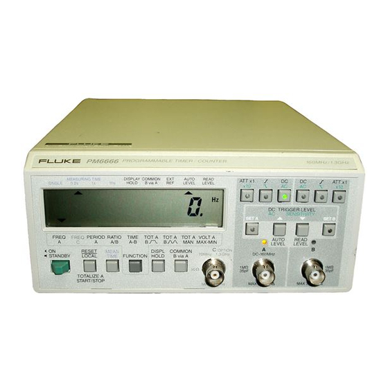
Page 5: Product Presentation
Page: 5 PRODUCT PRESENTATION General Rear View Rear feet. The PM 6666 is a compact, high resolution, reciprocal Screws for removing the cover. Timer/Counter which performs many functions. A number of options are available i.e. HF-input, GPIB-interface, high External-reference-input, BNC connector. - Page 6 *The selected function is indicated on the display. A short Set value button, depress to set sensitivity (AC) or trig- press on the button moves the cursor one step to the right. ger level (DC). A long press makes the cursor scroll. PM 6666 - OPERATORS MANUAL...
-
Page 7: Installation
PM 9608B PM 9605 has, file a claim with the carrier immediately, and notify the PM 9607 10MHz 0.5-15Vrms Fluke sales & service organization to make repair or re- placement of the instrument easier. THERMAL FUSE IN MAINS TRANSFORMER –... -
Page 8: Grounding
MTCXO, use a reference with an accuracy of 3*10 grounding is permitted for this Timer/Counter. Extension The PM 9691 oven-enclosed oscillator used in Fluke cables must always have a protective ground conductor. counters version /.5. meet this requirement, if calibrated. - Page 9 Location of the CALIB-Button. – Wait about 20 seconds, until the display shows 10.0000000 MHz. Now the oscillator is calibrated. – Switch OFF the counter and disconnect the 10 MHz ref- erence. – Fit the cover. PM 6666 - OPERATORS MANUAL...
-
Page 10: Operating Instructions
Move function cursor FREQ A SINGLE 0.2s HOLD B via A LEVEL LEVEL to FREQ A (FREQ B FUNCTION possible via Bus) FREQ FREQ PERIOD RATIO TIME TOT A TOT A TOT A VOLT A MAX-MIN FUNCTION PM 6666 - OPERATORS MANUAL... - Page 11 Timer/Counter off and on again. If error code Error 03 = Internal bus error 01 - 03 persists, call Fluke service. Look on the last page in Error OF = Overflow in the counting registers this manual for Phone No. and address.
- Page 12 TOTM A SINGLE 0.2s HOLD B via A LEVEL LEVEL TOT A MAN (TOTM B also FUNCTION possible via Bus) FREQ FREQ PERIOD RATIO TIME TOT A TOT A TOT A VOLT A MAX-MIN FUNCTION PM 6666 - OPERATORS MANUAL...
- Page 13 IZE START/STOP button (RESET/LOCAL). If you keep this button depressed for more than one second, the total sum The Measuring-time indicator is switched off in TOT A MAN. will be reset. Range: 0 to 1*10 pulses PM 6666 - OPERATORS MANUAL...
- Page 14 Move the measuring - MTIME 10 SINGLE 0.2s B via A LEVEL LEVEL HOLD MEAS time cursor to 10 s TIME FREQ FREQ PERIOD RATIO TIME TOT A TOT A TOT A VOLT A MAX-MIN FUNCTION PM 6666 - OPERATORS MANUAL...
- Page 15 A Frequency-A measurement will result in 6 to 7 digits on the display. A Frequency-A measurement will result in 7 to 8 digits on the display. A Frequency-A measurement will result in 8 to 9 digits on the display. PM 6666 - OPERATORS MANUAL...
- Page 16 TOT A TOT A TOT A VOLT A MAX-MIN operation. FUNCTION Connect the signal to 160MHz INPUT-A via a BNC- cable. 35pF MAX 30Vrms Connect the signal to INPUT-B via a BNC- cable. 35pF MAX 30Vrms PM 6666 - OPERATORS MANUAL...
- Page 17 Slope DC+Trigger level AC+Sensitivity DC/AC Switch Level Figure 7 Input Circuit Block Diagram. This input is used for Ratio A/B, Time A-B and TOT A start/stop (or gated) by B measurements. Range: Identical to Input-A PM 6666 - OPERATORS MANUAL...
- Page 18 NOTE: Sensitivity can You must first be set when AC-coupled select input FREQ FREQ PERIOD RATIO TIME TOT A TOT A TOT A VOLT A MAX-MIN and Trigger Level when with INPA or FUNCTION DC-coupled. INPB. PM 6666 - OPERATORS MANUAL...
- Page 19 Select AC-coupling and set the sensitivity so that the hyster- esis band of the Timer/Counter is about half the amplitude of the input signal. For time measurements: Select DC-coupling and set the trigger level to the desired level. PM 6666 - OPERATORS MANUAL...
- Page 20 10 MHz frequency controllable. source to the BNC- connector on the rear 10MHz 0.5-15Vrms panel of the Timer/Counter marked FREQ FREQ PERIOD RATIO TIME TOT A TOT A TOT A VOLT A MAX-MIN EXT REF INPUT. FUNCTION PM 6666 - OPERATORS MANUAL...
- Page 21 10 ± 0.1 MHz, 0.5 to 15 Vrms Sine wave. even if an external reference frequency is used. If single is selected, the EXT REF indicator on the display is not switched on until after the first measurement. PM 6666 - OPERATORS MANUAL...
-
Page 22: Battery Unit
If error code 01-03 per- nected to the mains, no matter how the Power-switch is sists, call Fluke service. Look on the last page in this man- set. Charging a discharged battery to 75 % of full capacity ual for Phone No. -
Page 23: Gpib-Interface Operation
Automatic un-addressing as talker when it is addressed What can I do using the Bus? as a listener. All the capabilities of the interface for the PM 6666 are ex- Listener Function, L4 plained below. If you want a complete description of all GPIB-interface functions, read the ‘Fluke Instrumentation-... -
Page 24: Connecting The Controller
4 if the counter has an HF-input, otherwise 0. face connector. The OFF position means 0 and the ON po- 3 for MTCXO, otherwise 1 sition means 1. 6 (GPIB-bus is installed) Revision No. of counter firmware Revision No. of GPIB-bus firmware PM 6666 - OPERATORS MANUAL... -
Page 25: Two Ways Of Programming
In some program commands, the body is replaced by the term <number> or <num>. Here you must enter a numeri- cal value. <number> can be entered in any format you like PM 6666 - OPERATORS MANUAL... -
Page 26: Selecting Output Separator
To return to the ‘bus only’ function you must re-program the counter. The specifications of some ‘bus-only’ functions differ from the specifications of it’s similar front-panel selectable func- tion. See ‘Specifications’. PM 6666 - OPERATORS MANUAL... -
Page 27: Selecting Measuring-Time
Default will stop the totalizing and reset the counting reg- 50 mV SENS 2 isters to zero. 100 mV SENS 3 If ATT10 is selected sensitivity will be 0.2 V 0.5 V and 1.0 V PM 6666 - OPERATORS MANUAL... -
Page 28: Free-Run/Triggered
Time-Out will be active again. Time-out can be switched on when free-run is on but it will not serve any purpose. 2 Ready to trigger 1 Meas. result ready Send MSR 67 to the counter. PM 6666 - OPERATORS MANUAL... -
Page 29: Status Byte
00001110 Calculating the can have the SRQ-mask set for SRQ at ready for trigger- measuring result. ing. This way the controller knows when it is possible to 00001111 XX0XXXX1 Measuring trigger the counter. result ready. PM 6666 - OPERATORS MANUAL... - Page 30 Overflow: 9.99999999E+9 High-speed Dump The most time-consuming part of a measuring cycle is cal- culating the result. The calculations limit the number of possible results/second to about 5, even when the Measur- ing-time is short. PM 6666 - OPERATORS MANUAL...
-
Page 31: Bus Learn
The following HP-85 program sets up a High-Speed dump Single-period measurement. OUTPUT 710;"PER A,MTIME 0" ENTER 710;A$ 000001.667E–4 OUTPUT 710;OUTM 4 ENTER 710;A$ JP000000000683 ‘J’ means that you must use formula J which is: −7 Reg . 3 ∗ 10 PM 6666 - OPERATORS MANUAL... -
Page 32: What Happens When I Switch To Local
Any one of the queries used for Bus Learn can be used to ask – If required, set the counter to Remote and program spe- the counter about its current setting, see ‘Bus Learn’ above. cial bus-functions from the controller. PM 6666 - OPERATORS MANUAL... -
Page 33: Programming Examples
This command must be placed at the end of a pro- COM OFF A and B separated. gram message. SENS <num> <num> = 1 gives 20 mV sensitivity <num> = 2 gives 50 mV sensitivity <num> = 3 gives 100mV sensitivity. PM 6666 - OPERATORS MANUAL... - Page 34 R1=R1*16+S NEXT I ! EVALUATE REGISTER 2 R2=0 FOR I=9 TO 14 S=NUM(B$[I,I])-48 IF S>=10 THEN S=S-7 R1=R2*16+S NEXT I ! EVALUATE RESULT IF F$="C" THEN R=10000000*R2/R1 IF F$="F" THEN R=R1*16^6+R2 IF F$="G" THEN R=R2/R1 PM 6666 - OPERATORS MANUAL...
- Page 35 COUNTER SETTING: TIME A;B This program example illustrates the ‘program data out’ MTIME 1.00,FRUN ON feature of PM 6666. By asking a set of queries, the TOUT 00.0 counter responds with its current setup. The output format MSR 000,OUTM 000...
- Page 36 This program prompts the user to input a programming se- This example runs on an IBM PC with an ‘IBM General quence. The sequence is then sent to the PM 6666 and Purpose Interface Bus Adapter’ instead of the Fluke the corresponding measuring result is read.
-
Page 37: Specifications
. × × PERIOD 2 5 10 age) measuring time Mode: Single time interval (SINGLE) for time interval measurements (at 0.2s, 1s or 10s measuring times) Ratio A/B (ratio B/A, C/A or C/B via GPIB/IEEE-488 only) PM 6666 - OPERATORS MANUAL... -
Page 38: Input Specifications
± 5V, 300 mV ± 3% of reading ±3% of Vp-p Sensitivity: 150 mVpp Inaccuracy 12 MHz to 50 MHz (A) or 1MHz to Trigger Indicators: Tri-state LED indicators; 5 MHz (B): On: Signal above set trigger level. PM 6666 - OPERATORS MANUAL... -
Page 39: Auxiliary Functions
1 LSD unit RESET The RESET button has three functions: Time A-B: Resolution (95% confidence level) equals 1 LSD unit or 100 ns/N, whichever is greater RESET: Starts a new measurement. The settings are not changed. LOCAL: PM 6666 - OPERATORS MANUAL... -
Page 40: General Information
Bump Test: According to IEC 68Eb Line Voltage: 115V or 230Vrms ± 15%; 45 Hz to 440 Hz; 20 VA PM 6666 including all options Handling Test: According to IEC 68Ec Safety: In accordance with IEC 348 Class 1 and CSA... -
Page 41: Optional Accessories
Recharging Time: 7 hours to approx 75% of full capac- grammed. The EOI-line can be programmed to be active to-gether with the last output byte sent. Battery Protection: Overcharge protection and deep discharge (auto shut-off) protection PM 6666 - OPERATORS MANUAL... -
Page 42: Ordering Information
To order the PM 6666 with standard 160 MHz input, The PM 9606/01 is a 19" wide Rack Mounting Adapter. It MTCXO Oscillator, and standard interface, select: can host one PM 6662, PM 6665, PM 6666 or PM 6669 ConfigurationPM 6666 Counter only. -
Page 43: Appendix 1
– Adjust the amplitude of the signal-source until the oscil- – Two BNC-cables, one short and one long. loscope indicates the sensitivity limit in the counter specifications. – Check that the counter is operating correctly. PM 6666 - OPERATORS MANUAL... -
Page 44: Checking The Sensitivity Of Counters
Check that the counter is operating correctly. ity (if adjustable). These procedures ensure unambiguous measurements of – Adjust the amplitude of the signal-source to the minimum the signal voltage at the input of the counter. level accepted by the counter. PM 6666 - OPERATORS MANUAL... -
Page 45: Index
External reference input Check list Connection ......20 GPIB program ....... 25 IBM GPIB Checking GPIB example ....... 36 GPIB communication .... 24 Free run COM B via A button From GPIB......28 GPIB........24 Location ........6 PM 6666 - OPERATORS MANUAL... - Page 46 Operating the controls....10 Description of function ...19 Selecting........7 Options Operation.......18 Installation ......8 Set value button Output mode Location ........6 GPIB ........30 Warning statements ......4 Short output format Output separator GPIB ........30 GPIB ........26 Slope PM 6666 - OPERATORS MANUAL...
Need help?
Do you have a question about the PM 6666 and is the answer not in the manual?
Questions and answers