
Subscribe to Our Youtube Channel
Related Manuals for Ballu BOGH-15


Summary of Contents for Ballu BOGH-15
- Page 1 1837 Operation manual Gas infrared heater Code-128 BOGH-15 BOGH-15E Before operating study this manual and keep it accessible...
-
Page 2: Table Of Contents
Contents Used notation Safety regulations General description Safety instruction Appliance design Specifications Preparation for work Control Maintenance Troubleshooting Transportation and storage Scope of supply Electrical schematic diagram Lifetime Warranty Disposal rules Date of manufacture Product certification 1. Used notation 3. The device must be installed in compliance with existing ATTENTION! local regulations and regulations for the use of gaseous Requirements which, if ignored, may result in serious... -
Page 3: Safety Regulations
2. Safety regulations device. • Do not cover the unit and do ATTENTION! not restrict the flow of air. • When operating an infrared Before turning on the infrared heater, follow general gas heater, remove foreign safety rules when using gas objects around it. - Page 4 may be tilted. Pay special manufacturer. attention to tilting the instrument. • For safety reasons for children, do not leave packaging (plastic • This product can be used outdoors or in a well-ventilated wrap, cardboard) unattended. area. • Do not allow children to play with plastic wrap.
-
Page 5: General Description
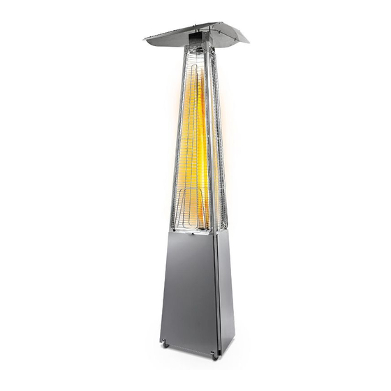
3. General description check the device and repair the leak with a qualified technician. Purpose • Do not install a working heater • Outdoor gas infrared heater has the shape of a trihedral pyramid, the base is made of a metal close to walls, curtains or frame on which decorative panels are mounted. -
Page 6: Safety Instruction
• The product must be repaired 4. Safety Instructions only by a qualified, authorized • Carefully read the instructions service center worker. before use. Familiarize yourself • To ensure safety, always turn with the device and methods off the gas cylinder before of controlling an infrared gas disassembling an infrared gas heater. -
Page 7: Appliance Design
5. Appliance design 5.1 Model BOGH-15 Fig. 2 – BOGH-15 model design 1. Glass flask in individual packaging; 2. The middle base of the gas heater assembly with the control unit;... - Page 8 AA battery electrical ignition adjustment knob choke control valve Fig. 3 - Design of the control unit for the model BOGH-15 Battery replacement: IMPORTANT! AA battery is used for electrical ignition. To replace the battery, unscrew the ignition cap •...
- Page 9 10. Protective grille (3 pcs.); 11. The top bar for the grille (3 pcs.); 12. Chain in the lavsan winding with two electrical ignition cover karabinas for fixing the gas cylinder; 13. Metal stoppers. Fig.4 - Replacing batteries for model BOGH-15...
- Page 10 Burner design tipping sensor ODS sensor D battery combustion chamber nozzle choke burner tube battery box tting tube-burner electronic control unit Fig. 6 - Design of the control unit for the model BOGH-15E Battery replacement IMPORTANT! For operation of the device, batteries of type D are used in the amount of 2 pcs.
- Page 11 • Used batteries are to be disposed of. • When disposing used batteries, follow the instructions indicated on their case and Fig.8 - Sensor position for model BOGH-15Е adhere regulations IMPORTANT! established in your country. • correct reliable operation, do not allow the...
-
Page 12: Specifications
6. Specifications Name of parameter BOGH-15 BOGH-15E Rated power, kW 13.0 13.0 Gas pressure in the reducer, mbar 37.0 37.0 Gas Consumption (min-max), kg/h 0.3-0.97 0.3-0.97 Propane, propane/ Propane, propane/ Fuel type butane butane Category products I 3B/P AT, BE, BG, CH, CY, CZ, DE, DK, EE, ES, FI, FR,... -
Page 13: Preparation For Work
7. Preparation for work the profile on this screw and tighten the screw 2, then tighten the screw 1; To build the device, you will need a screwdriver with a cross (or Phillips) slot; top pro le The assembled afterburner comes 1 assembled medium base with visor racks. - Page 14 • Install the grilles into the grooves of the upper profiles (Fig. 13); grooves for mounting the grilles Screw 4 Fig.11 - Installation of screws on the afterburner • Remove the flask from the box and carefully insert the flask, and install the afterburner onto the profiles (fig.12) from the top, fixing the flask, tighten the screws;...
- Page 15 M4x8 stainless steel screws. Attach the visor Gas connections cover with the M4x8 screws to the assembled • Connect the gas pressure regulator (regulator) visor. to the cylinder. The thread on the cylinder and the Visor cover gearbox is left. Visor element •...
-
Page 16: Control
Fig. 20 8. Repeat step 7 to secure the last stand. You should get the following (Fig. 21); Fig. 22 8. Control Fig. 21 9. Tighten all bolts with a wrench; IMPORTANT! 10. Reinstall the side and main covers. Tighten the screws that secure the side covers. - Page 17 10 °) to prevent otherwise the flame height may it from tilting. decrease. • Do not place the unit on an Startup sequence for Ballu BOGH-15 easily flammable surface (wood, model: linoleum, synthetic floors, etc.). • Ensure that the device is fully assembled;...
- Page 18 С а Р The shutdown sequence for the Ballu Fig.23 - Control panel panel for model BOGH-15 BOGH-15E model: • Open the main cover; Startup sequence for Ballu BOGH-15E • To disconnect, press the "Power" button on the model: electronic control panel several times depending on •...
-
Page 19: Maintenance
9. Maintenance gas cylinder cannot be refilled for more than 11 liters. and in IMPORTANT! a cylinder of 27 liters. not more • Before performing than 23 liters. maintenance operations, make IMPORTANT! sure that the gas supply valve is • It is recommended to store closed. -
Page 20: Troubleshooting
Replacing / cleaning flasks: If the flask is replaced or if it is necessary to clean it, disassemble the instrument in the reverse order (see the “Preparation” section), remove the flask (use personal protective equipment when disassembling) and clean it. 10. -
Page 21: Transportation And Storage
11. Transportation and storage - Screw M4 (24 pcs.), Screw M4 with countersunk head (4 pcs.) Are pre-twisted in the mounting holes; - AA battery (only for BOGH-15 model); IMPORTANT! - Butterfly nut M6 (3 pcs.); Never store the appliance with - Battery type AAA (2 pcs.) (Only for the model... -
Page 22: Lifetime
14. Lifetime batteries can be obtained from local authorities. This symbol may be indicated on batteries / batteries that contain harmful substances: The lifetime of the device is 5 years, subject to Pb - contains lead; compliance with the relevant rules for installation Cd - contains cadmium;... - Page 24 Importer: www.ballu.ru...
Need help?
Do you have a question about the BOGH-15 and is the answer not in the manual?
Questions and answers