Table of Contents
Advertisement
Quick Links
Advertisement
Table of Contents

Related Manuals for Hammer HB 450


Summary of Contents for Hammer HB 450
- Page 1 HYDRAULIC BREAKER HAMMER HB 450...
-
Page 3: Table Of Contents
11. TROUBLESHOOTING ....................................43 11.1 the hammer does not start ................................43 11.2 The hammer operates irregularly butthe blow has full power ................... 44 11.3 The hammer operates irregularly andblow has no power ....................44 11.4 Impact rate slows down ..................................44 11.5 The hammer does not stop or has run-on .......................... -
Page 4: Foreword
FOREWORD 1. FOREWORD 1.1 OPERATING MANUAL This data transfer document is arranged to provide necessary product information for documentation team when designing their manuals. Document contains information of the equipment and its safe operation. It also contains maintenance information, technical specifications and service instructions. 1.2 IMPORTANT SAFETY INFORMATION Basic safety precautions are outlined in the «Safety»... -
Page 5: Warranty
An installation inspection must be carried out after the product has been in-stalled on the carrier. In the installation inspection certain specifications (operating pressure, oil flow, etc.) are checked so that they are within givenlimits. See “Hammer specifications”. 1.4 SPARE PART ORDERS When you need spare parts or some information concerning maintenanceto your machinery, please contact your local dealer. -
Page 6: Machine Numbers
MACHINE NUMBERS 2. MACHINE NUMBERS 2.1 MODEL AND SERIAL NUMBER The equipment serial number is stamped on the valve body. The model andserial number are also located on the CE marking. Check that the model cor-responds to the one given on the cover of this manual. It is important to make correct reference to the serial number of the attach-ment when making repairs or ordering spare parts. -
Page 7: Product Introduction
No additional pressure accumulators are necessary since the integratedpressure accumulator absorbs hydraulic pressure peaks. The impact energy of the hammer is almost constant and independent of the carrier’s hydraulic system. -
Page 8: Provided Lifting Points
The local, national safety standards for machines and lifting-tackles must always be strictly observed. Note: The lifting eye must always be removed from the hammer and replaced with a blanking screw before starting to operate hammer. - Page 9 PRODUCT INTRODUCTION...
-
Page 10: Safety Instructions For Lifting
PRODUCT INTRODUCTION 3.4 SAFETY INSTRUCTIONS FOR LIFTING Below are some common safety instructions concerning lifting operations.In addition to this, the local, national standards for machines and lifting-tackles must always be strictly observed. Please Note that the list below is notall inclusive, you must always ensure the procedure you choose is safe foryou and others. ■... -
Page 11: Main Parts
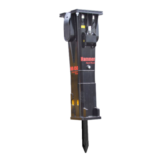
PRODUCT INTRODUCTION 3.5 MAIN PARTS The main parts of the hammer are shown below. A. Housing B. Mounting flange C. Vibration dampening elements D. Hose connections (pressure and return lines) E. Pressure accumulator F. Greasing device G. Tool retaining mechanism H. -
Page 12: Safety
SAFETY 4. SAFETY 4.1 GENERAL SAFETY All mechanical equipment can be hazardous if operated without due care orcorrect maintenance. Most accidents involving machine operation andmaintenance are caused by failure to observe basic safety rules or precautions. An accident can often be avoided by recognizing potentially hazardous situations before an accident occurs. - Page 13 SAFETY CLOTHING You can be injured if you do not wear proper clothing. Loose clothing canget caught in the machinery. Wear protective clothing to suit the job. Examples are: a safety helmet, safety shoes, safety glasses, wellfittingoveralls, earprotectors and industrial gloves.
- Page 14 To protect yourself from airborne pollutants, always keep excavator doorsand windows closed during operation. Excavators with pressurized cabinsshould be utilized in hammer operation. Proper maintenance of fresh air filters of the excavator is essential. Where pressurized cabins are not available, proper respirators must be utilized.
- Page 15 Wear ear protection against high noise level to prevent personal injury. EQUIPMENT LIMITS Operating the product beyond its design limits can cause damage. It canalso be dangerous. See “Hammer specifications”. Do not try to enhance the product’s performance by unapproved modifica-tions.
- Page 16 The hammer incorporates one or two pressure accumulators, depending onthe model. The accumulators are pressurized even when there is no hydraulic pressure to the hammer. Attempting to dismantle the accumulators without first releasing the pressure can cause injury or death. Do not try todismantle pressure accumulators, contact your local dealer first.
- Page 17 Note that welding of the hammer tools will render them uselessand make the warranty void. METAL SPLINTERS You can be injured by ffying splinters when driving metal pins in and out. Usesoftfaced hammer or drifts to remove and fit metal pins, such as pivot pins.Always wear safety glasses.
-
Page 18: Operation
Operating the hammer near residential areas or ot her noise sensitive areas can cause noise pollution. In order to avoid unnece ssary noise, please follow these basic rules: 1. When operating with the hammer, keep the tool at 90 degree angle to the material and t he feed force inli ne with the tool. - Page 19 ■ For igneous (e.g. granite) and tough metamorphic rock (e.g. gneiss) intowhich the tool doesn’t penetrate. ■ Concrete. ■ Breaking boulders. It is important to choose a tool, which is suitable for your hammer and for theapplication you are working on. The tool selection available depend on ham-mer model. See “Tool specifications”.
- Page 20 5.1.5 IDLE SELECTOR The hammer includes idle stroke preventing system as a standard feature.Frequent idle strokes have a deteriorating effect on the hammer. Idle strokepreventing system can be turned ON or OFF by the operator. Idle selector can be used to warm up the hammer and oil before operation.
- Page 21 5.1.8 STROKE SELECTOR VALVE Long piston stroke mode Long piston stroke mode gives the hammer high impact energy. Use longstroke mode when breaking hard rock (impact breaking). See illustration 1. hort piSton Stroke mode factory Setting Short piston stroke mode gives the hammer high impact rate.
-
Page 22: Daily Operation
The hammer as a standard assembly, must not be used under water. Ifwater fills the space where the piston strikes the tool, a strong pres-sure wave is generated and the hammer may be damaged. - Page 23 6. When demolishing vertical structures (e.g. brick walls), place the toolagainst the wall at a 90 degree angle. 7. Start the hammer. 8. A safety screen is recommended to protect the operator from flying debris. Keep the cabin windows and doors closed during operation.
- Page 24 10. Do not strike in one spot for more than 15 seconds at a time. If the objectdoes not break, or if the tool does not penetrate, stop the hammer andchange the position of the tool. Working too long in one spot will createstone dust under the tool.
- Page 25 OPERATION 14. Stop the hammer quickly. Do not allow the hammer to fall down and make idle strokes when an object breaks. Frequent idle strokes have a deteriorating effect on the hammer. If the hammer falls through, thehousing wears out more quickly.
- Page 26 OPERATION 18. Do not use the hammer to sweep the ground of debris. This may damage the hammer and the housing will wear out more quickly. 19. When operating the hammer, make sure that it does not make contactwith the carrier boom or hydraulic lines.
-
Page 27: Mounting And Dismounting The Hammer
1. Install hammer in the same manner as mounting a bucket. Install bucket pins. 2. Connect hoses. Hammer inlet port is marked on the valv e body with «IN» and outlet port with «OUT». An installation insp ection must be carried out after the product has been mounted on th e carrier. In the installation in- spection certain specific ations (operating pressu re, oil flow, etc.) are checked so that they... -
Page 28: Movement
The hammer as a standard assembly, must not be used under water. Ifwater fills the space where the piston strikes the tool, a strong pres-sure wave is generated and the hammer may be damaged. -
Page 29: Storage
5.7 STORAGE LONG TERM STORAGE Observe the following points when the hammer is stored. In this way the vitalparts of the attachment are protected from rust and the machine is ready tobe used whenever necessary. 1. The storage area must be dry. -
Page 30: Turning Hammer Left- Or Right-Handed
OPERATION 5.8 TURNING HAMMER LEFT- OR RIGHT-HANDED It is possible to make the hammer either left- or right-handed by turning thehammer inside the housing 180 degree. Warning! The hydraulic pressure inside the hammer must always bereleased before removing any of the plugs or valves. - Page 31 OPERATION 7. Disconnect grease hose and pressure hose from hammer. 8. Install two lifting eyes. Lift hammer out of housing. 9. Turn hammer 180 degree around. 10. Check that wear plates are in correct positions. 11. Lower hammer into housing.
-
Page 32: Hammer Tool Greasing
Warning! Wear gloves when handling the grease containers. If you get greaseonto your skin, wash it away with water. 6.2 MANUAL GREASING Manual greasing is always possible even if the hammer is equipped with theautomatic greasing device. Manual greasing is necessary if there is nogrease cartridges available, greasing device has malfunction or pressurehose is damaged. -
Page 33: Automatic Greasing
2. Stop carrier engine and wait 10 minutes for oil pressure to drop insidehammer. 3. Apply tool grease from grease gun to greasing points marked with thefollowing sticker. Note: The hammer must stand upright resting on the tool to ensure that thegrease will penetrate downwards between the tool and the bushing. -
Page 34: Carrier Hydraulic Oil
Thetemperature in the tank must not exceed the maximum allowed. The hammer must not be started if the ambient temperature is below freez-ing and the oil is very thick. The machine must be moved to bring the oil tem-perature above 0°C before hammering can start (viscosity 1000 cSt or 131°E). - Page 35 ■ The corrosion resistance properties must be good enough Note: Although a special oil could be used in the carrier, always check itssuitability with the hammer due to high piston speed of the hammer. Contactthe oil manufacturer or your local dealer for more...
-
Page 36: Oil Cooler
HAMMER TOOL GREASING 7.2 OIL COOLER The correct place to connect the hammer return line is between the oil coolerand the main filters. The hammer return line should not be connected beforethe oil cooler. Routing the hammer return flow through the cooler, mightdamage either the cooler, due to pulsating flow, or the hammer, due to increased back pressure. - Page 37 Note: Component damage is only a symptom. The trouble itself will not becured by removing the symptom. After any component damage due to impurities in the oil, the entire hydraulic system has to be cleaned. Dismantle,clean and reassemble the hammer and change the hydraulic oil.
-
Page 38: Routine Maintenance
■ Check that the hammer moves normally inside the housing and that vibration dampening elements (pads and buffers) are in good condition. ■ Check the condition of wear plates by moving hammer with a pry barfrom side to side inside housing. The maximum allowed clearance is approximately ±10 mm. -
Page 39: Maintenance Intervals In Special Applications
After every half hour operation ■ Grease the tool shank and the tool bushings through the grease nipples. ■ Check that the hammer moves normally inside the housing and that thebuffers are in good condition ■ Check all hoses and connections ■... -
Page 40: Removal Of Tool
Tool and tool retaining pins Tool grease REMOVAL OF TOOL Warning! The hydraulic pressure inside the hammer must always bereleased before removing the tool. After operating the hammer, wait 10minutes for oil pressure to drop inside hammer. Warning! Hot tool can cause severe injuries. - Page 41 7. Remove tool. Use lifting device if necessary. If the tool can not be removed contact your local dealer. Note: If hammer is still on carrier, it may be easier to stick the tool in theground and lift the hammer off the tool.
-
Page 42: Lower Tool Bushing
ROUTINE MAINTENANCE 10. LOWER TOOL BUSHING WEAR LIMITS AND LUBRICANTS FOR LOWER TOOL BUSHING Grease grooves are worn out. Tool bushing (worn out) Bushing must be replaced. Contact surfaces of front head Thread grease FOR REPLACEMENT OF THE LOWER SLEEVE CONTACT THE SERVICE CENTER. -
Page 43: Troubleshooting
Turn idle selector off or increase feeding force against object. PISTON IS IN ITS LOWER HYDRAULIC BRAKE Keep the hammer control valve open and force the tool against an object.The tool head will push the piston out of its brake area. See “Daily operation”. -
Page 44: The Hammer Operates Irregularly Butthe Blow Has Full Power
OIL HAS OVERHEATED (OVER +80°C/+176°F) Check for a fault in the oil cooling system or an internal leak in the hammer.Check the hydraulic circuit of the carrier. See “Measuring hammer circuit”. Check the relief valve operation in the carrier. Check the line size.Assemble an extra oil cooler. -
Page 45: The Hammer Does Not Stop Or Has Run-On
HAMMER OPERATING PRESSURE IS NOT REACHED Check the installation. Check the relief valve operation. Adjust the reliefvalve in hydraulic circuit. Measure the high pressure in the hammer inlet line. Contact your local dealer for more information. See “Measuring hammer circuit”. See “Measuring hammer operating pressure”. -
Page 46: Recurrent Tool Failure
Check the installation. Check the pump and the other hydraulic components. INTERNAL OIL LEAK IN THE HAMMER The hammer must be serviced in an authorized Tradicia-K service shop. See “Body parts”. EXCESSIVE BACK PRESSURE IN RETURN LINE Check the installation. See “Measuring hammer circuit”. Checkthe size of the return line. -
Page 47: Further Assistance
■ Grease and pressure hoses are installed backwards. Swap the hoses. ■ To continue troubleshooting, disconnect the grease hose from the hammer valve body and operate the hammer. After 10 minutes of operationcheck if grease has protruded from the grease hose. -
Page 48: Hammer Specifications
HAMMER SPECIFICATIONS 12. HAMMER SPECIFICATIONS 12.1 TECHNICAL SPECIFICATIONS Item Specification Working weighta 3380 kg Impact rate, Long strokeb 400...560 bpm Impact rate, Short strokec 520...700 bpm Operating pressured 150...160 bar Pressure relief, mine 210 bar Pressure relief, max 210 bar Oil flow range 250...350 l/min... -
Page 49: Main Dimensions
HAMMER SPECIFICATIONS 13. MAIN DIMENSIONS HB 450... -
Page 50: Tool Specifications
TOOL SPECIFICATIONS 14. TOOL SPECIFICATIONS Length, Weight, Diameter, Tool Part no. Chisel (A)) H00000991 1450 Moil point (B) H00000993 1450 Blunt (C) H00000994 1265 Pyramid (D) H00000993K3 1450 Hard rock chisel (E) H00000991A2 1450 Super blunt (G) H00000994T2 1265... - Page 52 www.hhammer.ru...
Need help?
Do you have a question about the HB 450 and is the answer not in the manual?
Questions and answers