
Related Manuals for Eaton Power Xpert XGIS


Summary of Contents for Eaton Power Xpert XGIS
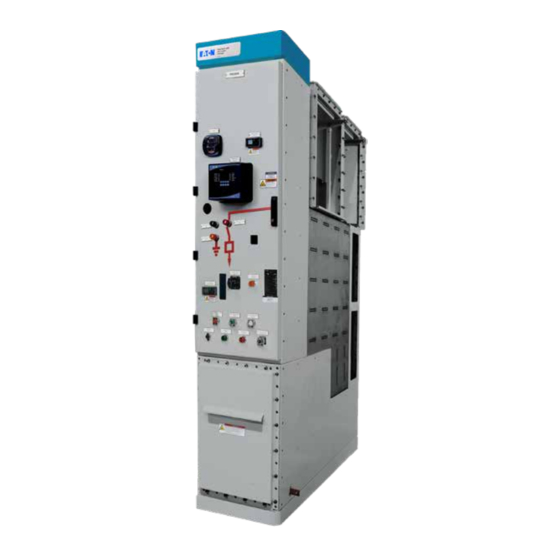
- Page 1 Instruction Booklet IB022017EN Effective July 2020 Instructions for the operation and maintenance of Power Xpert XGIS gas insulated switchgear...
- Page 2 Instruction Booklet IB022017EN Instructions for the operation and maintenance of Power Xpert Effective July 2020 XGIS gas insulated switchgear EATON www.eaton.com...
- Page 3 THE COURSE OF DEALING OR USAGE OF TRADE, ARE MADE REGARDING THE INFORMATION, RECOMMENDATIONS, AND DESCRIPTIONS CONTAINED HEREIN. In no event will Eaton be responsible to the purchaser or user in contract, in tort (including negligence), strict liability or otherwise for any special, indirect,incidental or consequential damage or loss...
-
Page 4: Table Of Contents
1.3 Power Xpert XGIS elements ........ - Page 5 Table 9. Recommended inspections ........... .46 EATON www.eaton.com...
- Page 6 BY QUALIFIED PERSONNEL. THIS INSTRUCTION BOOK SHOULD NOT BE CONSIDERED ALL INCLUSIVE REGARDING INSTALLATION OR MAINTENANCE PROCEDURES. IF FURTHER INFORMATION IS REQUIRED, YOU SHOULD CONTACT EATON. m WARNING DO NOT ATTEMPT ANY WORK ON THIS EQUIPMENT SUCH AS INSTALLING COMPONENTS, PERFORMING ANY EXAMINATIONS, PERFORMING ANY ADJUSTMENTS, PERFORMING ANY SERVICING, OR PERFORMING ANY MAINTENANCE WHILE IT IS ENERGIZED.
-
Page 7: Section 1: Introduction
This information should be given to the Eaton sales office if a question should arise concerning the switchgear or if renewal parts are required. This information is sufficient for Eaton to find the manufacturing information for the switchgear. -
Page 8: General Information
XGIS gas insulated switchgear 1.2 General information The purpose for this document is to provide instructions for Low Voltage operation and maintenance of Power Xpert XGIS gas insulated Wireway switchgear (referred to as Type XGIS gas insulated switchgear from (Top) this point forward). - Page 9 Switch Operator Vacuum Vacuum Rear Circuit Breaker Circuit Breaker Arc Relief Mechanism Compartment Cable Cable Tank Compartment Cable Connectors Cable Clamp Braces 3PDS = Three Position Disconnect Switch Figure 3. XGIS 1250 A cable connection section, side view EATON www.eaton.com...
- Page 10 VT Earthing Relief Switch Operator Rear Vacuum Arc Relief Circuit Breaker Compartment Vacuum Mechanism Circuit Breaker Tank Bus Tie Compartment Bus Joints 3PDS = Three Position Disconnect Switch Figure 4. XGIS 1250 A bus tie section, side view EATON www.eaton.com...
-
Page 11: Power Xpert Xgis Elements
Instruction Booklet IB022017EN Instructions for the operation and maintenance of Power Xpert Effective July 2020 XGIS gas insulated switchgear 1.3 Power Xpert XGIS elements Low-voltage compartment Voltage Detection System Low-voltage panel Meters and relays Three position disconnect switch Tank pressure... -
Page 12: Standard Features
Low-voltage control wiring is routed from the internal vertical can be much more compact than air-insulated equipment. section terminal boards to an Eaton blue colored top hat, above the Power Xpert XGIS vertical section characteristics low-voltage compartment. Control wiring from vertical section to An XGIS vertical section is divided into two functional areas: low- vertical section in a lineup is routed through these top hats. - Page 13 Behind the low-voltage panel and above the output cable compartment, the gas tank is the heart of the XGIS switchgear. The tank is pressurized to slightly over atmospheric pressure with SF gas, to insulate the MV components inside the tank. EATON www.eaton.com...
- Page 14 If repairs inside the tank are required, an XGIS switchgear includes a three-pole medium-voltage three-position Eaton service representative should be contacted. disconnect switch (3PDS) in the tank. Each phase pole consists of a piston on a screw drive. This linear travel device is mechanically The gas tank includes a fitting and gauge for gas pressure coupled to its operating mechanism through the tank wall.
- Page 15 The contacts are used in the electric (normal operation). control system to signal three-position disconnect switch status: closed, opened and grounded. The three-position disconnect switch and circuit breaker are mechanically and electrically interlocked to prevent inappropriate operation. EATON www.eaton.com...
- Page 16 The “PUSH TO OPEN” button is protected by a pad-lockable cover. The cover status is indicated by an electrical interlock block mounted on the breaker frame top. Figure 19. 3PDS locking features - standard. EATON www.eaton.com...
-
Page 17: Ground Bus
The XGIS three-position disconnect switch and circuit breaker are Circuit breaker trip-free features extensively mechanically and electrically interlocked to prevent The Eaton XGIS vacuum circuit breaker incorporates electrical inappropriate operation. trip-free characteristics. That is, the contacts of the circuit breaker must return to the open position and remain there when an opening 1.3.2 Ground bus... -
Page 18: Bracing
An auxiliary section side wall is bolted to the end sheet of lineup end vertical sections. In addition, an angle is attached to the auxiliary section rear panel and to the side of the vertical section end sheet. See Figure 27. EATON www.eaton.com... - Page 19 If the system utilizes a ducted arc exhaust (required to achieve an arc resistant rating), then a top mount VT cannot be installed in the same vertical section to which the arc duct connects. Figure 31. Unfused remote voltage transformer (mounted in cable vault). Figure 28. Fused voltage transformer. EATON www.eaton.com...
- Page 20 Main bus CTs can be furnished on the horizontal bus in the space above the gas tank, with the SSIS conductors passing through the CTs before terminating at the tank bushings. Main bus CT and bracket dimensions will differ depending upon the CT rating and applicable standards. EATON www.eaton.com...
- Page 21 Figure 36. Example 1250 A main bus CT. Figure 35. Example main bus CT mounting brackets. Figure 36 shows a 1250 A ANSI main bus CT. Figure 37. Example 2000 A / 2500 A main bus side CT EATON www.eaton.com...
- Page 22 Figure 42 shows 1250 A cable connection CTs mounted to the front of the tank. Figure 40 and Figure 41 show examples of cable side current transformers. The 1250 A CT fits over one bushing per phase while the 2500 A CT fits over two bushings per phase. EATON www.eaton.com...
- Page 23 SSIS bus. In that case, a different SF tank is used, the output bushings are mounted vertically in the tank bottom, and connected to bus joints connecting SSIS bus sections. EATON www.eaton.com...
- Page 24 When surge arresters are included, they replace one of the power cable connectors, allowing a maximum of two power cable connections per phase. Figure 48 shows an example surge arrester designed for connection using tee type connectors. EATON www.eaton.com...
-
Page 25: Xgis Vertical Section Configurations
Effective July 2020 XGIS gas insulated switchgear NOTE: TEE CONNECTORS NOT INCLUDED NOTE: TEE CONNECTORS NOT INCLUDED POWER XPERT XGIS CABLE GROUNDING KIT 1250 A, ONE CABLE POWER XPERT XGIS CABLE GROUNDING KIT Figure 49. XGIS cable grounding kit, one cable. - Page 26 It can be furnished with a set of VTs be furnished with fused VTs with a disconnect switch, cable CTs, with the VT disconnect switch and bus CTs. remote-mounted fused VTs or surge arresters. Figure 52. Feeder/incoming ANSI one-line. Figure 53. Bus tie ANSI one-line. EATON www.eaton.com...
- Page 27 VTs with the VT disconnect switch and bus CTs. with fused VTs with a disconnect switch, cable CTs, remote- mounted fused VTs or surge arresters. Figure 54. Bus sectionalizer ANSI one-line. Figure 55. Disconnector ANSI one-line. EATON www.eaton.com...
- Page 28 Figure 56. Cable connector one-line. Table 2, Table 3 and Table 4 list the vertical section dimensions, electrical data and relevant standards for Power XPert XGIS switchgear. Table 5 lists the Power XPert XGIS switchgear rated operating conditions. EATON www.eaton.com...
-
Page 29: Type Xgis Gas Insulated Switchgear Ratings (Tables 2, And 3)
Number of operations - No-load or full load > 10,000 / > 2,000 Three-position disconnect switch Number of operations ≥ 2000 Heat Loss for representative sections 1250 A 683 W 2000 A 905 W 2500 A 1554 W EATON www.eaton.com... - Page 30 ≤ 35° C on average over 24 hours ≥ -5° C ≤ 1000 m Altitude Contact Eaton for applications above 1000 m. Atmosphere No dust, smoke or corrosive or inflammable gas or vapor, or salt (clean industrial air) Storage conditions To retain all of the functional qualities when stored for prolonged periods, we recommend that the equipment be stored in its original packaging, in well-ventilated, clean, and dry conditions, sheltered from the sun and rain, at a temperature ≥...
-
Page 31: 1250 A Vertical Section
Instruction Booklet IB022017EN Instructions for the operation and maintenance of Power Xpert Effective July 2020 XGIS gas insulated switchgear 1.5 XGIS vertical section outlines and dimensions 1.5.1 1250 A vertical section Figure 57. 1250 A vertical section EATON www.eaton.com... -
Page 32: 2000 A / 2500 A Vertical Section
Instruction Booklet IB022017EN Instructions for the operation and maintenance of Power Xpert Effective July 2020 XGIS gas insulated switchgear 1.5.2 2000 A / 2500 A vertical section Figure 58. 2000 A / 2500 A vertical section dimensions. EATON www.eaton.com... -
Page 33: Ssis Conductor System
There are two bus joint types and two connection types. The Type C bus joint serves 1250 A bus, and provides connections in either cross or end configurations. The Type F bus joint serves 2500 A bus, and also provides connections in either cross or end configurations. EATON www.eaton.com... -
Page 34: Power Cable Conductors In Xgis Switchgear
The maximum number of cable connectors possible depends on the XGIS rating. Multiple connectors per phase are configured using tee or elbow type separable connectors (Figure 64). A surge arrester can be connected as the last connected device. EATON www.eaton.com... - Page 35 The separable connectors include a shield layer that is used to ground the exterior of the connectors. The ground wires must be fastened to the compartment ground bus. This will ensure the outer surface of the separable connectors are at ground potential. EATON www.eaton.com...
-
Page 36: Voltage Detection System
XGIS front panel face and operates in accordance with IEC 61243-5 (integrated voltage detection systems). This system looks for the presence of voltage in each of the three phases and indicates the line status using LED display symbols on the device display. EATON www.eaton.com... -
Page 37: Sf Gas Handling
This desiccant is specific to the XGIS switchgear. The desiccant catalog number is 87A1040H01. Figure 68 shows the desiccant placed in the tank bottom. Figure 68. XGIS gas tank desiccant. EATON www.eaton.com... -
Page 38: Section 3: Safe Practices
• hands, faces and exposed skin immediately. Tools and PPE must also be cleaned. MUST NOT be discharged into the atmosphere. It should be • collected and may be reused only after treatment and testing by qualified experts. EATON www.eaton.com... -
Page 39: Section 4: Description And Operation
A cam limit switch assembly in the operating mechanism signal the three- position disconnect switch operating position. EATON www.eaton.com... -
Page 40: Operation
Figure 69 shows a typical vertical section front panel devices layout. Actual layouts will depend upon customer custom features. Refer to the project drawings for installed details. Ω ® ® Power Xpert XGIS Power Xpert XGIS ® ® Gas Insulated Gas Insulated... -
Page 41: Three Position Disconnect Switch (3Pds)
Repeat steps 2. and 3. to move the contacts to the next operating position. When the desired position has been achieved, as confirmed by the Switch Position indicator windows, remove the tool and close the manual operation cover. EATON www.eaton.com... -
Page 42: Circuit Breaker
Following is Table 8 which indicates how the two devices’ status affects what operations are possible for each device. Refer to the project schematics and three-position disconnect switch controller program for details. EATON www.eaton.com... - Page 43 The three-position disconnect switch is switched to the ground 4.2.2.8 Circuit breaker trip free operation position. Verify this state by viewing. The Eaton XGIS vacuum circuit breaker incorporates electrical d. Close the circuit breaker. trip-free characteristics. That is, the contacts of the circuit breaker e.
-
Page 44: Voltage Transformer Earthing Switch
WARNING Ground, and must be in one of these two positions at all times. THE POWER XPERT XGIS SWITCHGEAR DESCRIBED IN THIS DOCUMENT When the VT earthing switch is in either the Connect or Ground ARE DESIGNED AND TESTED TO OPERATE WITHIN ITS NAMEPLATE position, it is held in place by a spring-loaded latch that must be RATINGS. - Page 45 Figure 75. VT earthing switch in Ground position. Figure 73. Grip the handle. Pull the release arm out. Let go of the release arm Continue to rotate the switch handle toward the desired position until the release arm locks back into place (see Figure 74). EATON www.eaton.com...
-
Page 46: Section 5: Inspection, Maintenance, And Testing
• ALL PARTS OF THE SYSTEM BEING INSPECTED MUST BE DE-ENERGIZED AND EARTHED. The Power Xpert XGIS product is designed such that no SF handling should be required during installation and commissioning • PROTECTIVE PLATES MUST ONLY BE REMOVED AFTER THE of the gear. -
Page 47: Cleaning Viewing Ports
5.4.1 Typical test Prior to beginning any testing, confirm that the equipment is de-energized. Below is a list of common tests that may be performed on the XGIS switchgear. Consult Eaton engineering services for more information. XGIS test list: Voltage withstand test •... -
Page 48: Current Test
Power Xpert Effective July 2020 XGIS gas insulated switchgear 5. Install an insulating dummy plug, Eaton Catalog Number 87A1025H01. 6. Secure the dummy plug to the VT port by tightening the bolts to 13 Nm (115 in.-lb.) See Figure 77, below. -
Page 49: Section 6: Renewal Parts
See technical document TD022003EN for a list of XGIS renewal parts. Contact Eaton engineering services for more information. 6.2 Ordering instructions For ordering details for XGIS switchgear renewal parts, refer to technical document TD022003EN. -
Page 50: Notes
Instruction Booklet IB022017EN Instructions for the operation and maintenance of Power Xpert Effective July 2020 XGIS gas insulated switchgear Notes: EATON www.eaton.com... -
Page 51: Notes
Instruction Booklet IB022017EN Instructions for the operation and maintenance of Power Xpert Effective July 2020 XGIS gas insulated switchgear Notes: EATON www.eaton.com... - Page 52 1000 Eaton Boulevard Cleveland, OH 44122 United States Eaton.com © 2020 Eaton All Rights Reserved Eaton is a registered trademark. Printed in USA All other trademarks are property Publication No. IB022017EN / TBG 001430 July 2020 of their respective owners.
Need help?
Do you have a question about the Power Xpert XGIS and is the answer not in the manual?
Questions and answers