Table of Contents
Advertisement
Quick Links
Advertisement
Table of Contents

Related Manuals for SBC PCD1.M2220-C15


Summary of Contents for SBC PCD1.M2220-C15
- Page 1 Manual PCD1.M2220-C15 E-Line CPU Document 27-640 – Version ENG03 | 2020-03-25...
-
Page 2: Table Of Contents
LED operating states ................3-11 Run/Stop button ..................3-12 Watchdog (relay) ................... 3-13 3.9.1 .. as a watchdog function ..............3-13 3.9.2 .. as a relay output ................. 3-15 Hardware manual PCD1.M2220-C15 │ Document 27-640 – Version ENG03 │ 2020-03-25... - Page 3 Digital inputs on-board ................8-5 Analogue inputs on-board ..............8-6 Special function ..................8-8 8.6.1 Watchdog relay for monitoring or as relay output ........8-8 Maintenance Maintenance-free .................. 9-1 Hardware manual PCD1.M2220-C15 │ Document 27-640 – Version ENG03 │ 2020-03-25...
- Page 4 Switching inductive loads ..............A-5 A.3.4 Specifications of the relay manufacturer about the dimensioning of the RC elements ......... A-5 Abbreviations ..................A-7 Glossary ....................A-8 Contact ....................A-10 Hardware manual PCD1.M2220-C15 │ Document 27-640 – Version ENG03 │ 2020-03-25...
-
Page 5: Document Process
Saia-Burgess Controls AG. ® Technical changes are subject to the latest technical developments. Saia-Burgess Controls AG, 2020. © All rights reserved. Published in Switzerland Hardware manual PCD1.M2220-C15 │ Document 27-640 – Version ENG03 │ 2020-03-25... -
Page 6: Graphic Overview
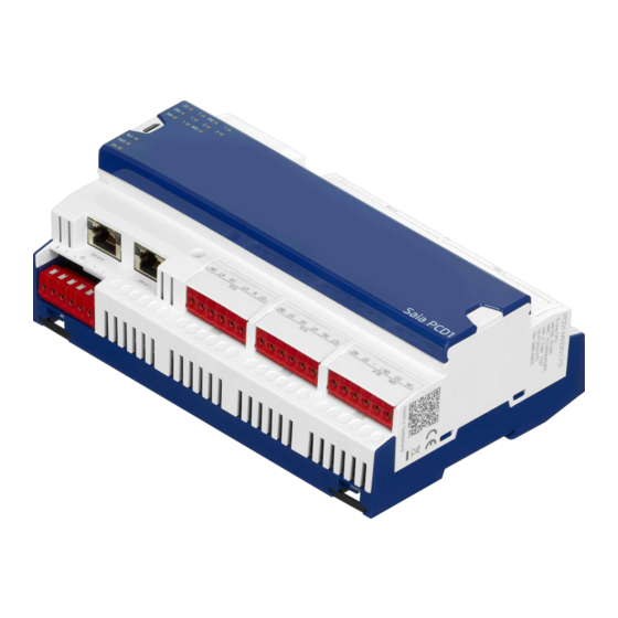
WD LED USB connection 5.2.1 Operating LEDs Firmware Power supply Ethernet connection RUN/STOP Terminals for on-board in- 2.5.2 (2 port switch) 5.2.2 button 3.8 puts/outputs and watchdog relay 6.1.1 Hardware manual PCD1.M2220-C15 │ Document 27-640 – Version ENG03 │ 2020-03-25... -
Page 7: Guidance
System catalogue 26-215 Saia PG5 programming tool 26-732 ® Programming in the instruction list 26-733 I/O modules 27-600 System cables and adapters 26-792 Ethernet TCP/IP 26-776 RS-485 network 26-740 Hardware manual PCD1.M2220-C15 │ Document 27-640 – Version ENG03 │ 2020-03-25... -
Page 8: Introduction
PCD controllers include simple, integrated protection features. However, se- cure operation on the Internet is only guaranteed using external routers with a firewall and encrypted VPN connections. For more information, please refer to our support site: www.sbc-support.com/security Hardware manual PCD1.M2220-C15 │ Document 27-640 – Version ENG03 │ 2020-03-25... -
Page 9: Planning An Application
For most applications, it must be noted that the outputs represent the largest load on the 24V power supply. For 16 outputs with a load output of 0.5A each, the load is still 8A if all the outputs are switched on. Hardware manual PCD1.M2220-C15 │ Document 27-640 – Version ENG03 │ 2020-03-25... -
Page 10: Wiring
● For cables installed outdoors, the shielding must have a suitable power cable capacity and be earthed at both ends. ● The overvoltage conductor should be installed at the inlet of the switch cabinet. Hardware manual PCD1.M2220-C15 │ Document 27-640 – Version ENG03 │ 2020-03-25... -
Page 11: Addressing The Inputs And Outputs (I/O)
All inputs and outputs on the CPU board (on-board) are assigned with the device configurator (device configurator in the PG5 tool) by the programmer to flags and registers (media mapping). Hardware manual PCD1.M2220-C15 │ Document 27-640 – Version ENG03 │ 2020-03-25... - Page 12 Further details are included in chapter 3.9 and 3.10 Watchdog. Plug-in input/output modules The IO module slots are designated with Slot 0 and Slot 1 on the device. Slot will henceforth be used as a term in this manual. Hardware manual PCD1.M2220-C15 │ Document 27-640 – Version ENG03 │ 2020-03-25...
-
Page 13: Assembly
0°C and 55°C is permitted for this mounting position. Vertical mounting is preferable. In all other positions, the air flow is less favourable and an ambient temperature of 40°C may not be exceeded. Hardware manual PCD1.M2220-C15 │ Document 27-640 – Version ENG03 │ 2020-03-25... -
Page 14: Mounting On Din Rails
(pull approx. 5 mm towards it) and lift up the upper edge of the DIN rail. 5. Remove the PCD 6. Press both locking slides back with your thumbs to the initial position until the locking sound can again be heard. Hardware manual PCD1.M2220-C15 │ Document 27-640 – Version ENG03 │ 2020-03-25... -
Page 15: Slot Cover For Pcd2-I/O Plug-In Module Slot 0 And 1
16 outputs 5 36VDC/0.5A Information such as module versions, details, functional description, connection assignment, etc. can be found in the manual at www.sbc-support.com under Doc- uments -> Manuals -> “27-600_GER_Handbuch EA-Module.pdf” Hardware manual PCD1.M2220-C15 │ Document 27-640 – Version ENG03 │ 2020-03-25... -
Page 16: Process Slot Cover
Two protruding lugs, left and right of the slot cover, facilitate gripping when push- ing up. The following work steps on the next three pages apply to both slots. 2-10 Hardware manual PCD1.M2220-C15 │ Document 27-640 – Version ENG03 │ 2020-03-25... - Page 17 If the upper slot cover must also be removed, continue with step 5, otherwise deburr the resulting rough breaking edge with a file or knife. Warning: risk of injury! 2-11 Hardware manual PCD1.M2220-C15 │ Document 27-640 – Version ENG03 │ 2020-03-25...
- Page 18 Bend the lower part of the slot on the side up and down until it breaks off. Step 7: Deburr the resulting rough breaking edge with the file or knife. Warning: risk of injury! 2-12 Hardware manual PCD1.M2220-C15 │ Document 27-640 – Version ENG03 │ 2020-03-25...
- Page 19 - The designation Slot 0 and Slot 1 and the M1 Flash of the memory extension would be missing. - Rough parts could fall inside the device and cause short circuits. 2-13 Hardware manual PCD1.M2220-C15 │ Document 27-640 – Version ENG03 │ 2020-03-25...
-
Page 20: Handling Pcd2 I/O Modules
Make sure that the metal claws of the shielding plate are not bent inwards with a tool (never lever out with a screwdriver). This could result in a short circuit and damage the module or controller. 2-14 Hardware manual PCD1.M2220-C15 │ Document 27-640 – Version ENG03 │ 2020-03-25... -
Page 21: Power Supply And Earth Concept
Power supply and earth concept Power supply and earth concept There is a shielding plate in the upper part of the PCD1.M2220-C15 housing. If an I/O module is inserted in a slot, the metal claws of the shielding plate in the PCD-1 housing form reliable, multiple contact points with the module. -
Page 22: 24Vdc Supply
Slot 0 Slot 1 Termination PCD2.E110 Port0 Port1 M1 Flash DB-/DA+ DB-/DA+ Halt Saia PCD1 D DI2 Eth 0.0 Eth 0.1 earthing bar 1.5 mm / max. 25 cm 2-16 Hardware manual PCD1.M2220-C15 │ Document 27-640 – Version ENG03 │ 2020-03-25... -
Page 23: 24Vac Supply
M1 Flash DB-/DA+ DB-/DA+ Halt Saia PCD1 D DI2 Eth 0.0 Eth 0.1 earthing bar 1.5 mm / max. 25 cm The AC and DC part is electrically isolated. 2-17 Hardware manual PCD1.M2220-C15 │ Document 27-640 – Version ENG03 │ 2020-03-25... -
Page 24: Cpu / Processor Unit
When switched off, the power reserve of the hardware clock is retained for a minimum of 10 days (typically 20 days) The USB port “USB 1.1 Slave Device 12 Mbps” is used for programming. Hardware manual PCD1.M2220-C15 │ Document 27-640 – Version ENG03 │ 2020-03-25... -
Page 25: General Technical Details
- (2 kV CM and 1 kV DM for AC I/O without shielding Conducted disturbances, pursuant to EN61000-4-6: 10 V 150 kHz-80 MHz induced by high-frequency fields Emitted interference in accordance with EN61000-6-4 for the industrial sector Hardware manual PCD1.M2220-C15 │ Document 27-640 – Version ENG03 │ 2020-03-25... -
Page 26: Hardware Version Number
This can be used to check if a function is included with the hardware. This can be ascertained in the Saia PG5 Online Configurator under Hardware ® Info or on the laser inscription on the right side of the PCD1. Hardware manual PCD1.M2220-C15 │ Document 27-640 – Version ENG03 │ 2020-03-25... -
Page 27: Firmware (Cosinus Update)
● In the Tools menu, select “Update Firmware” and select the path for the file of the new firmware version with the Search function. Make sure that only one file is selected for the download ● Start the download Hardware manual PCD1.M2220-C15 │ Document 27-640 – Version ENG03 │ 2020-03-25... -
Page 28: System Memory Structure
128 MB file system (maximum of 2,500 files or 625 directories) memory Flash memory extensions Memory extension (number: 1) PCD7.Rxxx Memory structure of a PCD1.M2220-C15 with additional memory cards Hardware manual PCD1.M2220-C15 │ Document 27-640 – Version ENG03 │ 2020-03-25... -
Page 29: Flash Memory Structure On Pcd1.M2220-C15
Used for linked web projects (web builder) 3.5.3 SD card on IO slot (PCD2.R6000) The PCD2.R6000 memory module is not supported on the PCD1.M2220-C15 as the SD card cannot be mechanically secured. Hardware manual PCD1.M2220-C15 │ Document 27-640 – Version ENG03 │ 2020-03-25... -
Page 30: Flash Memory Modules Pcd7.Rxxx For The File System
BACnet® is inserted in the M1 flash slot provided for this. Summary of the memory modules for PCD1 CPU The on-board memory of the Saia PCD1.M2220-C15 can be expanded using a Saia PCD7.Rxxx module in slot M1. In addition, it can be expanded with BACnet ®... -
Page 31: System Resources
FB ... PB ... Subprogram and functional program blocks FB 0 PB 0 SB 31 (95) SB ... SB 0 Sequential program blocks Step 0..2000 (..6000) Transition 0 ..2000 (..6000) Hardware manual PCD1.M2220-C15 │ Document 27-640 – Version ENG03 │ 2020-03-25... -
Page 32: Data Types/Value Ranges
The number of configured timers should not be greater than required to prevent unnecessary CPU loads Hardware manual PCD1.M2220-C15 │ Document 27-640 – Version ENG03 │ 2020-03-25... -
Page 33: Data Retention
The following resources are saved in the FRAM: ● Register ● Flags ● Timer ● Counter ● Strings (TEXT) ● Data blocks (DB) The E-Line CPUs are maintenance-free and therefore do not require a battery. 3-10 Hardware manual PCD1.M2220-C15 │ Document 27-640 – Version ENG03 │ 2020-03-25... -
Page 34: Led Operating States
- No communication mode for S-Bus PGU or Gateway Master Port System diagnosis Reset The RESET status is caused by the following: - Power supply too low - Firmware not started 3-11 Hardware manual PCD1.M2220-C15 │ Document 27-640 – Version ENG03 │ 2020-03-25... -
Page 35: Run/Stop Button
If the button is pressed for longer than 3 seconds, the last user program saved is loaded from the plug-in flash memory extension (M1 flash). 3-12 Hardware manual PCD1.M2220-C15 │ Document 27-640 – Version ENG03 │ 2020-03-25... -
Page 36: Watchdog (Relay)
The PCD1.M2220-C15 CPUs are equipped as standard with this type of hardware watchdog function, or “watchdog” for short. The active watchdog, i.e. contact... - Page 37 For short cycle times, the code sequence must be repeated several times in the user program to prevent the watchdog dropping out during the RUN operation! 3-14 Hardware manual PCD1.M2220-C15 │ Document 27-640 – Version ENG03 │ 2020-03-25...
-
Page 38: As A Relay Output
See “6.1.4 Digital output” > “Connection assignment for relay output” Device configuration The function of the relay must be selected in the PG5 “Device Configurator”. On-board inputs and outputs Properties overview 3-15 Hardware manual PCD1.M2220-C15 │ Document 27-640 – Version ENG03 │ 2020-03-25... - Page 39 Mapping table for the status of the relay outputs Using media mapping or direct access, the relay can be switched on or off similar to any other digital output. Example FUPLA: 3-16 Hardware manual PCD1.M2220-C15 │ Document 27-640 – Version ENG03 │ 2020-03-25...
-
Page 40: Watchdog (Software)
“XOB 0” Call-ups are entered in the PCD history as follows: “XOB 0 WDOG START” if XOB 0 was triggered by the Software Watchdog “XOB 0 START EXEC” if XOB 0 was triggered by a supply error 3-17 Hardware manual PCD1.M2220-C15 │ Document 27-640 – Version ENG03 │ 2020-03-25... -
Page 41: Program Download And Backup
The download of the user program in the E-Line CPU with Saia PG5 and the ® backup and restoration of the user program is described in the PG5 Help. 3-18 Hardware manual PCD1.M2220-C15 │ Document 27-640 – Version ENG03 │ 2020-03-25... -
Page 42: Rio (Remote I/O)
E-Line module Expansion options of the PCD1.M2220-C15: - via Ethernet with the PCD3.T66x RIOs - via Profibus with the PCD3.T76x RIOs - via RS-485 with the E-Line modules Hardware manual PCD1.M2220-C15 │ Document 27-640 – Version ENG03 │ 2020-03-25... -
Page 43: Communication Interfaces
5.1 Using the SBC S-Bus The SBC S-Bus stands for the proprietary communication protocol of the Saia PCD ® Read more about this in the manual “26-739_DE_Handbuch_SBC-SBus.pdf”. The SBC S-Bus is essentially designed for communication with engineering and de- bugging tools and to connect the management levels/process control systems. -
Page 44: On-Board
“Online Settings”: The activation of the “PGU Option” ensures that the PC can be directly connected to the PCD independent of the configured S-Bus address. Hardware manual PCD1.M2220-C15 │ Document 27-640 – Version ENG03 │ 2020-03-25... -
Page 45: Ethernet (Eth0.0/Eth0.1) Port #9
Link (connection) and activity LED green Speed off = 10 Mbits / On = 100 Mbits Port Cabling Standard Ethernet cable (e.g. Cat 5e) uncrossed and crossed are supported. Hardware manual PCD1.M2220-C15 │ Document 27-640 – Version ENG03 │ 2020-03-25... -
Page 46: Rs-485 (Port#0+1) Electrically Isolated (Terminal Block X1)
Port 0 Port 1 Termination Open Port0 Port1 DB- /DA+ DB- /DA+ Close PCD1.M2220-C15 RS-485 connections and terminating resistor switches (termination) for Port0 and Port1 LEDs Port0 and Port1 Hardware manual PCD1.M2220-C15 │ Document 27-640 – Version ENG03 │ 2020-03-25... - Page 47 /DA+ Termination Bus RS 485 RX - TX Pull down Segment length max. 1200 m 3300 Ohm max. 32 stations More details can be found in “26-740_DE_Handbuch_RS485-Komponenten Net- zwerke”. Hardware manual PCD1.M2220-C15 │ Document 27-640 – Version ENG03 │ 2020-03-25...
-
Page 48: Interfaces Using Pcd2 Plug-In Modules Pcd2.F2Xx
PCD1.M2220-C15, note the following: The communication volume is determined by the connected peripheral devices. For example, this applies if a PCD1.M2220-C15 is used as the S-Bus slave sta- tion. If the PCD1.M2220-C15 is bombarded with heavy telegram traffic at high baud rates, there is less CPU capacity to handle the actual application. - Page 49 - 2 interfaces with 57.6 kbps require approx. 50% of the CPU capacity. - 2 interfaces with 115 kbps require approx. 60% of the CPU capacity. ● If the PCD1.M2220-C15 is used as a master station, the communication volume and therefore the communication capacity is dependent on the user program in the PCD1.M2220-C15.
-
Page 50: Modem Communication
Analogue modem 33.6 kbit/s (RS-232 and TTL interface) PCD2.T851: Digital modem ISDN TA (RS-232 and TTL interface) The IO module modem PCD2.T8xx is not supported on the PCD1.M2220-C15. Please use external modems. Hardware manual PCD1.M2220-C15 │ Document 27-640 – Version ENG03 │ 2020-03-25... -
Page 51: Inputs And Outputs
Three options are described where the inputs and outputs can be located. These are: - On-Board - as plug-in modules - on RIOs On-board On-board denotes “mounted on the CPU motherboard”. For an overview, see the next subchapter 6.1.1 Hardware manual PCD1.M2220-C15 │ Document 27-640 – Version ENG03 │ 2020-03-25... -
Page 52: Connection Overview
DI 1 Digital input 1: 24V AC/DC Not assigned Digital ground Normally open Watchdog DI 2 Digital input 2: 24V AC/DC or relay Centre contact output Digital ground Normally closed Hardware manual PCD1.M2220-C15 │ Document 27-640 – Version ENG03 │ 2020-03-25... -
Page 53: Digital Inputs (Terminal Block X10, X14, X18)
Terminal technology Plug-inspring terminals up to 1.5 mm Definition of input signals for 24 V for 24 V 30 V 28 V 24 V 24 V 15 V 15 V -30 V Hardware manual PCD1.M2220-C15 │ Document 27-640 – Version ENG03 │ 2020-03-25... - Page 54 DC wiring “sink operation” (ground switching) In 0 AC voltage 24 VAC Digital inputs AC voltage wiring To constantly detect a ‘1’, the frequency must be at least 48 Hz for AC voltage! Hardware manual PCD1.M2220-C15 │ Document 27-640 – Version ENG03 │ 2020-03-25...
-
Page 55: Analogue Inputs (Terminal Block X10)
Hardware input filter time constant Voltage measurement τ = 5 ms resistance τ ≈ 2.2 ms Software input filter Connectible using Saia PG5 Device Configurator (forms the average value of the last 16 values) Hardware manual PCD1.M2220-C15 │ Document 27-640 – Version ENG03 │ 2020-03-25... - Page 56 (saiadbe, available from Saia-PCD Support) and the FBox “Conversion DB n Points”. Prefigured in the delivery state to –10… +10V (12 bit + sign). Hardware manual PCD1.M2220-C15 │ Document 27-640 – Version ENG03 │ 2020-03-25...
- Page 57 Each time the min./max. values are reached, the min./max. status flag is set. min. value max. value under value over range range 100% The status flag remains set until the status has been read. Hardware manual PCD1.M2220-C15 │ Document 27-640 – Version ENG03 │ 2020-03-25...
- Page 58 For direct access, the status flag is reset as soon as the user program reads the status flag. Connection diagram: Pt 1000 Ni 1000 0…2500 Ω 0…7500 Ω 0…300 kΩ -10…+10V Hardware manual PCD1.M2220-C15 │ Document 27-640 – Version ENG03 │ 2020-03-25...
-
Page 59: Digital Output
Watchdog function or user output (selectable) Max. voltage 48VAC or VDC Switching capacity 1A (with DC switch-on voltage, a freewheeling diode should be con- nected in parallel to the load) Hardware manual PCD1.M2220-C15 │ Document 27-640 – Version ENG03 │ 2020-03-25... - Page 60 WD-relay! (Possibly via power contactor) Process Configuration and description, see “3.9.1 … as a watchdog function” Connection assignment for relay output Configuration and description, see “3.9.2 … as a relay output” 6-10 Hardware manual PCD1.M2220-C15 │ Document 27-640 – Version ENG03 │ 2020-03-25...
-
Page 61: I/O Plug-In Modules For Slot 0 And Slot 1
I/O modules and I/O terminal blocks may only be removed or inserted when the Saia PCD is in a de-energised state. ® The external voltage supply of the modules +24V must also be switched off. 6-11 Hardware manual PCD1.M2220-C15 │ Document 27-640 – Version ENG03 │ 2020-03-25... -
Page 62: System Cables And Adapters
0.5 mm or 0.25 mm wires that are numbered and colour-coded. Cables with different connection technologies are described in the manual “System cables and adapters” document 26-792. Hardware manual PCD1.M2220-C15 │ Document 27-640 – Version ENG03 │ 2020-03-25... -
Page 63: Configuration
Information on PG5 software, programming, tools etc. is included in the manual “26-732_DE_Benutzerhandbuch_PG5” Manuals are never as up-to-date as the help pages in the respective tool of the PG5 packet. Hardware manual PCD1.M2220-C15 │ Document 27-640 – Version ENG03 │ 2020-03-25... -
Page 64: General
- direct access to programming instructions to read or transfer values from the peripheral module. The I/O handling is always activated for the PCD1.M2220-C15 via direct access, there is no bit access command. The minimum access range is “byte”. It is there- fore recommended to use media mapping to read or write all the I/O channels. -
Page 65: Device Configurator
8.3.2 Help Support for the Device Configurator can be found under the “Help” menu “Help Topics”: Click on one of the help topics: Hardware manual PCD1.M2220-C15 │ Document 27-640 – Version ENG03 │ 2020-03-25... -
Page 66: Media Mapping View
Example of a media mapping view To consider the respective of the respective resources, you can media mapping open the relevant window in three ways: button, and using the key shortcut “Alt + F5” Hardware manual PCD1.M2220-C15 │ Document 27-640 – Version ENG03 │ 2020-03-25... -
Page 67: Digital Inputs On-Board
In the PG5 Device Configurator for PCD1.M2220-C15 > under… Properties overview Media mapping yes/no Specify VDC or VAC inputs. Filter for DC: no = 0 ms or yes = 8 mapping table for digital inputs Hardware manual PCD1.M2220-C15 │ Document 27-640 – Version ENG03 │ 2020-03-25... -
Page 68: Analogue Inputs On-Board
Configuration (Device Configurator) Analogue inputs on-board 8.5 Analogue inputs on-board Properties Mapping device for values, status or diagnosis Channel device and scaling information Filter: Average value from the last 16 values. Hardware manual PCD1.M2220-C15 │ Document 27-640 – Version ENG03 │ 2020-03-25... - Page 69 Saia-Burgess Controls AG Configuration (Device Configurator) Analogue inputs on-board Mapping table for analogue inputs Mapping table for the status of the analogue inputs Hardware manual PCD1.M2220-C15 │ Document 27-640 – Version ENG03 │ 2020-03-25...
-
Page 70: Special Function
Special function 8.6.1 Watchdog relay for monitoring or as relay output A relay is installed in the PCD1.M2220-C15 that operates as a monitoring relay (watchdog) as standard. Its function is activated by the FBox of the same name in the user program. Alternatively, the relay can be used as an output (changeover contact) that is con- trolled using flags. -
Page 71: Maintenance
PCD1-CPUs do not contain parts that can be replaced by the user. If hardware problems arise, please return the components to Saia-Burgess Controls AG (see the chapter Appendix for the address). Hardware manual PCD1.M2220-C15 │ Document 27-640 – Version ENG03 │ 2020-03-25... -
Page 72: Appendix
Instructions with this character must always be complied with. A.1.2 Connection descriptions Symbol Description Function ground DGND digital ground AGND analogue ground SGND signal ground earth a, b, … alphanumeric index by different grounds Hardware manual PCD1.M2220-C15 │ Document 27-640 – Version ENG03 │ 2020-03-25... -
Page 73: Definition Of Serial Interfaces
To guarantee an error-free operation of a RS-485 network, the network should be terminated at both ends. Cables and terminating resistors should be selected in accordance with the manual 26-740 “Installation components for RS-485 networks”. Hardware manual PCD1.M2220-C15 │ Document 27-640 – Version ENG03 │ 2020-03-25... -
Page 74: Installation Regulations And Relay Contacts
1 phase for each module is permitted over 1 shared fuse. The individual load circuits can however be secured individually again. PCD2.A200 max. 10 A Burden max. 2 A PCD2.A210 max. 10 A Burden max. 2 A Hardware manual PCD1.M2220-C15 │ Document 27-640 – Version ENG03 │ 2020-03-25... - Page 75 Saia-Burgess Controls AG Appendix Installation regulations and relay contacts PCD2.A220 Burden max. 6 A max. 6 A Burden PCD2.A250 Charge max. 8 A max. 8 A Charge Hardware manual PCD1.M2220-C15 │ Document 27-640 – Version ENG03 │ 2020-03-25...
-
Page 76: Switching Inductive Loads
Only anti-interference capacitors in accordance with VDE 0565 T1 class X2 may be used in suppressors. These capacitors have a high switching capability and are designed for particularly high switching overvoltages. Direct operation on the mains voltage is also possible. Hardware manual PCD1.M2220-C15 │ Document 27-640 – Version ENG03 │ 2020-03-25... - Page 77 R curve. Load Example: U = 100V I = 1A C is therefore 0.1 μF R = 10 Ω (point of intersection with R-scale) Hardware manual PCD1.M2220-C15 │ Document 27-640 – Version ENG03 │ 2020-03-25...
-
Page 78: Abbreviations
Thermistor: Temperature sensors with negative temperature coefficient Element: Platinum (temperature sensors made of platinum) Temperature coefficient α = 3.92 · 10 –3 –1 PTC resistor: Temperature sensors with positive temperature coefficient Hardware manual PCD1.M2220-C15 │ Document 27-640 – Version ENG03 │ 2020-03-25... -
Page 79: Glossary
With a PWM output, it is possible to output analog values without expensive A/D converters. Random Access Memory → digital, volatile RAM of the computer. Retains data without a power supply. Hardware manual PCD1.M2220-C15 │ Document 27-640 – Version ENG03 │ 2020-03-25... - Page 80 “x” in the product description stands for a number 0... 9. In the following case, an additional two-digit number, i.e. PCD1. M2220-C15 = e.g. PCD1.M2220-C15. Hardware manual PCD1.M2220-C15 │ Document 27-640 – Version ENG03 │ 2020-03-25...
-
Page 81: Contact
E-mail Support: ...... support@saia-pcd.com Support website: ....www.sbc-support.com SBC website: ......www.saia-pcd.com International agencies & www.saia-pcd.com/contact SBC subsidiaries: Postal address for customers to return purchases in Switzerland: Saia-Burgess Controls AG After Sales Service Bahnhofstrasse 18 3280 Murten, Switzerland A-10 Hardware manual PCD1.M2220-C15 │ Document 27-640 – Version ENG03 │ 2020-03-25...
Need help?
Do you have a question about the PCD1.M2220-C15 and is the answer not in the manual?
Questions and answers