Table of Contents
Advertisement
Available languages
Available languages
Quick Links
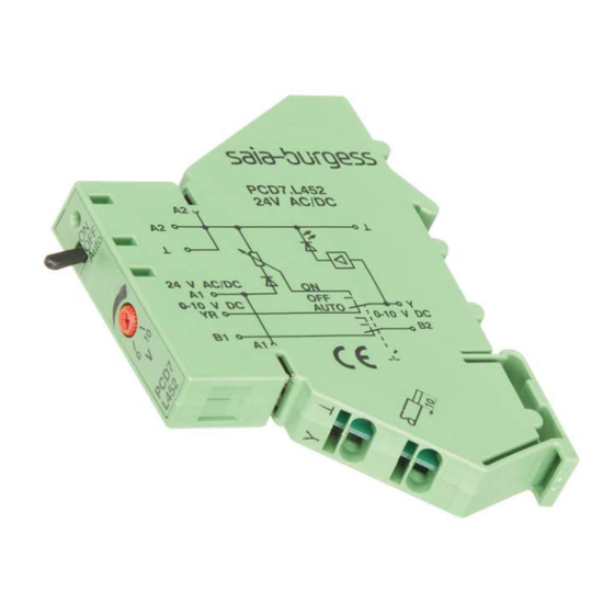
PCD7.L452 Coupling Module
Describtion
The analog data encoder PCD7.L452 is used as a regulating encoder for manual setting of
manipulated variables e.g. for mixing valves, valve settings, temperatures etc.
Function describtion
The module offers three operation modes selectable by the three-position switch (ON, OFF,
AUTO). The switch position is signaled by the external control contacts B1 and B2.
Switch position "ON"
The regulating variable is selected with the front-mounted potentiometer. The 0 to 10 V
output signal is available at contact Y.
Switch position "AUTO"
The regulating variable is looped through without change to output Y via contact YR
These coupling modules are provided with spring clamp terminal blocks allowing easy and
quick wire termination. No tool is required to terminate solid wires and stranded wires with
end sleeves. And to terminate stranded wires without end sleeves just a screwdriver will do.
The terminated wires are easy to release with a screwdriver.
Technical Data
Inputvoltage
0 ... 10 V DC
Outputvoltage
0 ... 10 V DC
Input
operating voltage U
24 V AC/DC
N
current consumption
at 24 V AC
max. 30 mA
at 24 V DC
19 mA
current consumption (input YR)
at 10 V DC
max. 2 mA
operating voltage range
0.85 ... 1.2 × U
duty cycle
100 %
status indication of the output
red LED, intensity of the LED is proportional to the
manipulated variable
switching AUTO/ON
proof against short-circuits
Breaking Capacity of Switch
breaking capacity max.
24 V / 50 mA AC/DC
breaking capacity min.
20 mV / 1 μA AC
mechanical endurance
5 × 10² switching cycles
test voltage
500 V, 50 Hz, 1 min.
Output
output current (output Y)
in switch positions
"AUTO/ON/OFF"
10 mA
Temperature range
operating temperature range
-20 °C ... +55 °C
storage temperature range
-25 °C ... +70 °C
Housing
type of protection (EN 60 529)
IP20
material
polyamide 6.6 V0
wire cross section
single wire
0.08 - 2.5 mm²
stranded wire w/o end sleeve
0.08 - 2.5 mm²
stranded wire with end sleeve 0.08 - 1.5 mm²
dimensions W × H × L
11.2 × 88 × 60 mm
weight
43 g
mounting position
any
mounting
Standard rail TH35 per IEC 60715
Mounting
On standard rail TH35 per IEC 60715 (35
And/or distribution panels.
Installation
Electric installation and device termination shall be done by qualified persons only,
by respecting the VDE specifications and local regulations.
1. Power down the equipment.
2. Strip the wire by 10 mm. Wire cross section:
Solid wire
0.08 – 2.5 mm²
Stranded wire w/o end sleeve 0.08 – 2.5 mm²
Stranded wire with end sleeve 0.08 – 1.5 mm²
a) Solid wires and wire with end sleeves are plugged directly
Insert the wire straight into the contact and press until the wire snaps
In the spring.
Saia-Burgess Controls AG
Bahnhofstrasse 18
3280 Murten / Switzerland
T+ 41 026 580 30 00
www.saia-pcd.com
N
×
7.5 mm), in junction boxes
b) When terminating stranded wires without end sleeves it is necessary
to open the spring with a flat-bladed screwdriver (blade width max.
3.0 mm): enter the screwdriver to the test sleeve situated below the
Contact and remove the screwdriver.
3. Device connection per wiring diagram.
Wiring
4. Release a wire
Open the spring by inserting a flat-bladed screwdriver
(blade width max. 3.0 mm) to the test sleeve situated
below the conact and remove the wire.
5. Release the Module from the standard rail
Slightliy push the clamp at the bottom of the module with a flat-bladed screwdriver and
draw off upwards.
Connecting Bridge
The connecting bridge (Order-Nr. PCD7.L291) allows to interconnect up to 10 coupling
modules (total currenct max. 2 A).
Cut the needed number of contacts with wire cutting pliers at the respective predetermined
cutting point. Then insert the connecting bridge from the top into the contact slot and press
it downwards into place.
The tails of the connecting bridge carry potential, therefore
place the bridge in the middle of the aligned modules to
eliminate any accidential touch.
Wiring diagram
899239
26-044 ENG06 06-2016
Advertisement
Table of Contents

Subscribe to Our Youtube Channel
Related Manuals for SBC PCD7.L452


Summary of Contents for SBC PCD7.L452
- Page 1 PCD7.L452 Coupling Module Describtion The analog data encoder PCD7.L452 is used as a regulating encoder for manual setting of manipulated variables e.g. for mixing valves, valve settings, temperatures etc. Function describtion The module offers three operation modes selectable by the three-position switch (ON, OFF, AUTO).
- Page 2 PCD7.L452 Koppelbaustein Beschreibung Der Analogwertgeber PCD7.L452 dient als Stellgrößengeber für manuelle Stellgrößen- vorgabe, z. B. Mischklappen, Ventilstellungen, Temperaturwerte usw. Funktionsbeschreibung Das Modul kann durch drei Betriebsarten gesteuert werden, welche mittels integriertem dreistufigen Schalter (ON, OFF, AUTO) umschaltbar sind. Über die externen Steuerkontaktklemmen B1 und B2 wird die Schalterstellung rückgemeldet.
Need help?
Do you have a question about the PCD7.L452 and is the answer not in the manual?
Questions and answers