Advertisement
Quick Links
CONTENTS
Specifications
Meter calibration
Bus configuration
Panel removal & interconnects
Parts Lists:
Input I/O PCB Assembly
Input Channels PCB Assembly
Input Panel Assembly
Output I/O PCB Assembly
Output PCB Assembly
Output Panel Assembly
Chassis Assembly
Power Supply PCB Assembly Rev A
Power Supply PCB Assembly Rev B
Power Supply Chassis Assembly
Miscellaneous
Block Diagram
Schematics & Service Diagrams
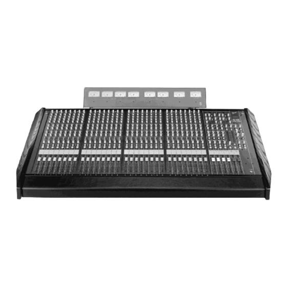
MX-5200 SERIES
PROFESSIONAL MIXING CONSOLES
SERVICE MANUAL
MX-5216 p/n 071-5216-000
MX-5224 p/n 071-5224-000
MX-5232 p/n 071-5232-000
Fender Musical Instruments Corp.
7975 North Hayden Road Scottsdale, AZ 85258
MX-5200 SERIES
(This is the model name for warranty claims)
The information contained herein is CONFIDENTIAL and PROPRIETARY to Fender Musical Instruments Co. It is
disclosed solely for use by qualified technicians for purposes of equipment maintenance and service. It is not to be
disclosed to others without the expressed permission of Fender Musical Instruments Co. All specifications subject to
change without notice.
Part numbers ending with the three digit suffix "001" indicate a component prepped with long leads.
For warranty repair service, only Fender specified part numbers are to be used. It is recommended they also be
used for post-warranty maintenance and repair.
*
Parts marked with an asterick (
) indicate the required use of that specific part. This is necessary for RELIABILITY
and SAFETY requirements. DO NOT USE A SUBSTITUTE!
A coded naming convention is used in the description of certain parts. The codes and what they mean are as
follows:
CAPACITOR CODES
CAP AE
=
Aluminum Electrolytic
CAP CA
=
Ceramic Axial
CAP CD
=
Ceramic Disk
CAP MPF =
Metalized Polyester Film
CAP MY
=
Mylar
CAP PFF
=
Polyester Film/Foil
RESISTOR CODES
RES CC
=
Carbon Comp
RES CF
=
Carbon Film
RES FP
=
Flame Proof
RES MF
=
Metal Film
RES WW
=
Wire Wound
1
OCTOBER 1995
IMPORTANT NOTICE:
HARDWARE CODES
BLX
=
Black Oxide
CR
=
Chrome Plated
HWH
=
Hex Washer Head
M
=
Machine Screw
NI
=
Nickel Plated
OHP
=
Oval Head Phillips
PB
=
Particle Board
PHP
=
Pan Head Phillips
PHPS
=
Pan Head Phillips Sems
SMA
=
Sheet Metal "A" Point
SMB
=
Sheet Metal "B" Point
SS
=
Stainless Steel
TF
=
Thread Forming
ZI
=
Zinc Plated
Advertisement

Related Manuals for Fender MX-5200 Series


Summary of Contents for Fender MX-5200 Series
- Page 1 Part numbers ending with the three digit suffix "001" indicate a component prepped with long leads. For warranty repair service, only Fender specified part numbers are to be used. It is recommended they also be used for post-warranty maintenance and repair.
- Page 2 SPECIFICATIONS METER CALIBRATION Specifications are subject to change without notice. Frequency Response: 20Hz. to 40kHz. ± 1dB METER CALIBRATION PROCEDURE Distortion: < .025%, 20Hz to 20kHz (Mic input to any line level mixer output) Metering of any input or output is provided by two twelve segment LED bargraphs, with VU Signal to Noise Ratio: >...
- Page 3 BUS CONFIGURATION PANEL REMOVAL AUXILIARY BUS PRE/POST CONFIGURATION Remove the top trim piece. The screws are located above the rear patch bay. The standard factory MX-5200 Auxiliary Bus configuration is: Remove the two (2) flathead screws at the top of the panel. •...
- Page 4 PARTS LIST PARTS LIST 8 CHANNEL INPUT 8 CHANNEL INPUT I/O PRINTED CIRCUIT BOARD ASSEMBLY PRINTED CIRCUIT BOARD ASSEMBLY NOTE: NOTES: AN "X" IN A REFERENCE DESIGNATOR EQUALS 1-8. AN "X" IN A REFERENCE DESIGNATOR EQUALS 1-8. 8 INPUT CHANNELS PER CIRCUIT BOARD. 8 INPUT CHANNELS PER CIRCUIT BOARD.
- Page 5 PARTS LIST PARTS LIST 8 CHANNEL INPUT PANEL ASSEMBLY 8 CHANNEL INPUT PRINTED CIRCUIT BOARD ASSEMBLY CONTINUED QTY PART # DESCRIPTION REFERENCE DESIGNATION 047703 PANEL ASSY INPUT MX5200 PCB mounted in panel QTY PART # DESCRIPTION REFERENCE DESIGNATION 041832 BUTTON SWITCH 5.5X10MM GRAY @Solo switches(SX6) 041831 BUTTON SWITCH 5.5X5.5MM GRAY...
- Page 6 PARTS LIST PARTS LIST OUTPUT/MASTER PRINTED CIRCUIT BOARD ASSEMBLY OUTPUT I/O PRINTED CIRCUIT BOARD ASSEMBLY NOTES: NOTES: "X" IN A REFERENCE DESIGNATOR = 1-4 "Y" IN A REFERENCE DESIGNATOR = 5-6 "X" IN A REFERENCE DESIGNATOR = 1-4 "Z" IN A REFERENCE DESIGNATOR = 7-8 "Y"...
- Page 7 PARTS LIST PARTS LIST OUTPUT/MASTER OUTPUT/MASTER PRINTED CIRCUIT BOARD ASSEMBLY PRINTED CIRCUIT BOARD ASSEMBLY CONTINUED CONTINUED QTY PART # DESCRIPTION REFERENCE DESIGNATION QTY PART # DESCRIPTION REFERENCE DESIGNATION 047178 CONTROL VERT DUAL 100KB R534(Control Room), R627(Solo Level), 047233001 RES CF 1/6W RX04,RY04 R640(Headphone),RX50(Return Level) 047235001...
- Page 8 PARTS LIST PARTS LIST CHASSIS ASSEMBLY PANEL ASSEMBLY OUTPUT/MASTER QTY PART # DESCRIPTION REFERENCE DESIGNATION QTY PART # DESCRIPTION REFERENCE DESIGNATION 047747 ARMREST ASSY MX5216 047748 ARMREST ASSY MX5224 047704 PANEL ASSY OUTPUT MX5200 PCB mounted in panel 047749 ARMREST ASSY MX5232 041832 BUTTON SWITCH 5.5X10MM GRAY @Solo switches(S1,SX3,5,6,SZ2)
- Page 9 CPSM-4 POWER SUPPLY MODULE CPSM-4 POWER SUPPLY MODULE PARTS LIST PARTS LIST REV "A" MX-5200 POWER SUPPLY PRINTED CIRCUIT BOARD ASSEMBLY THE FOLLOWING SECTION CONTAINS TWO DIFFERENT PARTS LISTS FOR THE PRINTED CIRCUIT CONTINUED BOARD ASSEMBLY. THE "REV A" PARTS LIST REFERS TO THE REV A CIRCUIT BOARD. THE "REV B" PARTS LIST REFERS TO THE REV B CIRCUIT BOARD.
- Page 10 CPSM-4 POWER SUPPLY MODULE CPSM-4 POWER SUPPLY MODULE PARTS LIST PARTS LIST REV "B" REV "B" MX-5200 POWER SUPPLY MX-5200 POWER SUPPLY PRINTED CIRCUIT BOARD ASSEMBLY PRINTED CIRCUIT BOARD ASSEMBLY CONTINUED QTY PART # DESCRIPTION REFERENCE DESIGNATION QTY PART # DESCRIPTION REFERENCE DESIGNATION...
- Page 11 CPSM-4 POWER SUPPLY MODULE PARTS LIST MX-5200 POWER SUPPLY CHASSIS ASSEMBLY QTY PART # DESCRIPTION REFERENCE DESIGNATION 049033 CHS ASSY POWER SUPPLY MX52XX 047190 CABLE MX5200 PWR INTERCONNECT From power supply to mixer 047189 CABLE MX REC/F-PNL MT 1FT 6CKT From P1 of PCB Assy to rear of Chassis.
Need help?
Do you have a question about the MX-5200 Series and is the answer not in the manual?
Questions and answers