Table of Contents
Advertisement
Advertisement
Table of Contents

Related Manuals for 3M Convenience Store D-2400


Summary of Contents for 3M Convenience Store D-2400
- Page 1 Convenience Store Intercom System Model D-2400 Installation Instructions...
- Page 2 This device must accept any interference received including interference hat may cause undesired operation. Changes or modifications not expressly approved by the party responsible for compliance could void the user’s authority to operate the equipment. Trademarks Safety Guidelines Warranty Information 3M Information Call (800) 328-0033...
- Page 3 3M Model D-2400 Date Revision 5/00 6/00 7/00 7/00 7/00 8/00 1/01 Revision Record Reason For Change Preliminary manual released. Incorporated changes from Revision 01. Incorporated changes from Revision 02. Incorporated changes from Revision 03 Released manual Incorporated changes from Revision A...
-
Page 4: Table Of Contents
Outbound Music/Messaging Level (Only for Systems That Use Music/Messaging) ...14 Station Selector(s)...14 Inbound Audio Volume Level ...14 VOX (Voice Activated Transmission) Sensitivity Level...14 Testing the Functions...15 Training Users ... 17 Configuration Worksheets ... 19 Table of Contents 3M Model D-2400... -
Page 5: System Components
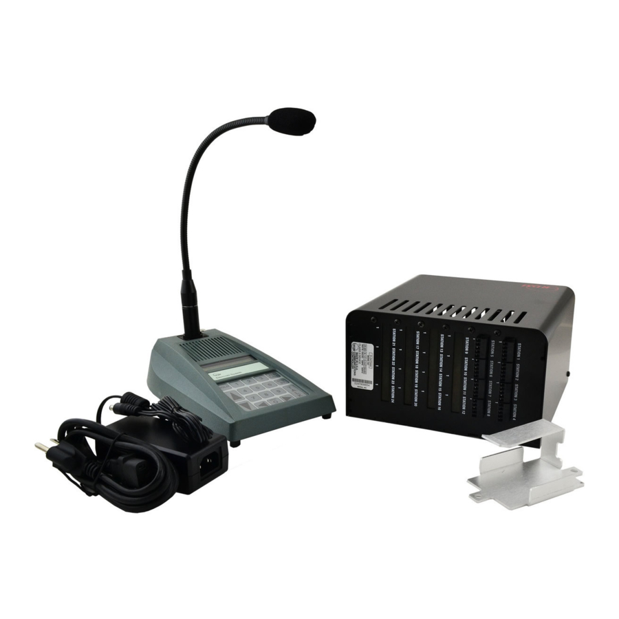
3M Model D-2400 System Components The 3M™ Model D-2400 Convenience Store Intercom System consists of one of the following components: Station Selectors Call Stations Communcations Controller Figure 1. Model D-2400 Convenience Store Intercom System Components Material Required (not supplied) Assortment of screws, anchors, and cable clamps Sufficient twisted pair sets of audio cable to connect other components such as Station Selector, Call Staions, etc. - Page 6 3M Model D-2400 System Components This page intentionally left blank.
-
Page 7: Component Placement
3M Model D-2400 Component Placement This section describes placement of the 3M™ Convenience Store Intercom System, Model D-2400, components: Communications Controller For proper system operation, locate the Communications Controller: 1. Near the conduit termination of the Call Station wiring. 2. Near the power source. -
Page 8: Call Stations
3M Model D-2400 Component Placement Call Stations For proper system operation, install the Call Stations in locations: 1. Chosen for ease of use. 2. At least 48 inches above the pavement. ü Note Local codes may dictate placement of call stations. -
Page 9: Wiring The System
Depending on distance use twisted pair, 14-22 AWG audio cable when wiring Convenience Store Intercom System, Model D-2400, components. Figure 5 shows an overview of the cable types and number of connectors required for each unit. Table 1 shows wire gauge required for different distances between components. -
Page 10: Configuration Worksheets
Wiring Station Selectors involves connecting a minimum of 7 wires: 3 audio wires and 4 power and communications wires. The D-2400 System is powered by one power supply that provides power for the Communications Controller and a maximum of three Station Selectors. An individual power supply must be plugged into the rear of each Station Selector that exceeds the three Station Selector limit. -
Page 11: Programming The System
3M Model D-2400 Programming the System Programming the System Program the system to conform to your planned configuration and desired operation. Hardware (Jumpers) Select Call Station(s) to receive ALL CALL and music/messaging during STANDBY mode. (A closed jumper turns ALL CALL and music/messaging OFF. An open circuit jumper turns ALL CALL and music/messaging ON.) 1. -
Page 12: Programming The Selector
Doing this allows you to change the ID number to a lower value (start at 1) and avoid the erratic behavior caused by multiple selectors sharing the same ID number. To program the D-2400, it is necessary to put the system in the programming state. From this state, the entire system is configured and all memorized parameters are adjusted. -
Page 13: Keypad Function Definitions (Programming State)
3M Model D-2400 Keypad Function Definitions (Programming State) MENU SP-389C Figure 6. D-2400 Key- Key functions are defined below. HOLD (Shift) Shifts between upper and lower case for text data. UP ARROW Increments data by 1. Fields wrap around. DOWN ARROW Decrements data by 1. - Page 14 Jump right to next data field. Exits the programming state and enters Off Line mode. Clear the data field to its default value (space for text or the default value). Enter key where appropriate. 3M Model D-2400 & ’ “ <...
-
Page 15: Error Message
3M Model D-2400 Error Message ! E R R O R ! NO COMMUNICATION Parameter Selection 01:Selector ID # {01} 02:Max Stations {16} 03:Alert Volume {08} 04:Alert Type {Chime} 05:VOX Enable {Off} 06:VOX Sensitive {15} The system will display one error message: No Communication. - Page 16 Release the ALL CALL key. Confirm the re-initialize procedure by pressing the TALK key. (To abort, press the STD BY key.) Remember to adjust all of the parameters so that the Selector functions properly in its given installation. 3M Model D-2400...
-
Page 17: Adjusting The System
3M Model D-2400 Adjusting the System Communications Controller You must remove the cover from the Communications Controller to perform the following adjustments. Outbound ALL CALL Volume Level To set the outbound ALL CALL Volume Level: 1. Ask another attendant to stand near a Call Station that is not in use. -
Page 18: Outbound Music/Messaging Level (Only For Systems That Use Music/Messaging)
The VOX adjustments are necessary only if VOX is enabled for your system. The VOX sensitivity level determines the maximum distance from the microphone that the speaker can activate communication. The suggested average activation distance from the microphone to the attendant is 2 to 6 inches. Important Important 3M Model D-2400... -
Page 19: Testing The Functions
Press the ALL CALL key to exit Programming mode. Testing the Functions Perform the following tests after installing the Convenience Store Intercom System, Model D-2400: 1. Checking TALK/LISTEN switching. a. Ask an attendant to go to Call Station 1 and press the call button. - Page 20 Adjusting the System 3M Model D-2400 This page intentionally left blank.
-
Page 21: Training Users
3M Model D-2400 Training Users Train users of the Convenience Store Intercom System, Model D-2400, by performing the following steps: 1. Powering the system up (it should remain on). 2. Answering a call. 3. Initiating a call. 4. Adjusting inbound volume. - Page 22 Training Users 3M Model D-2400 This page intentionally left blank.
-
Page 23: Configuration Worksheets
3M Model D-2400 Configuration Worksheets Configuration Worksheets... - Page 24 TO ADDITIONAL STATION SELECTORS RECORD WIRE COLORS CONFIGURATION WORKSHEET 2 RECORD RECORD WIRE COLORS WIRE COLORS RECORD WIRE COLORS 3M Model D-2400 IMPORTANT RECORD SETTINGS AND WIRE COLORS. STORE THIS DOCUMENT IN THE COMMUNICATIONS CONTROLLER. TO POWER RECORD WIRE COLORS SP-412C...
-
Page 25: Audio Connections
3M Model D-2400 CONFIGURATION WORKSHEET 3 COMMUNICATIONS CONTROLLER-STATION SELECTOR AUDIO CONNECTIONS MUSIC/MESSAGE SOURCE RECORD WIRE COLORS COMMUNICATIONS CONTROLLER D - 2400 RECORD WIRE COLORS Configuration Worksheets IMPORTANT: RECORD WIRE COLORS. STORE THIS DOCUMENT IN THE COMMUNICATIONS CONTROLLER. TO POWER TO ADDITIONAL... - Page 26 Food Services Trade Department 3M Center St. Paul, MN 55144-1000 Printed on recycled paper. Printed in U.S.A. © 3M 2001 January 78-6912-0725-8 Rev C...