Table of Contents
Advertisement
Quick Links
M1601 |
USER'S AND INSTALLER'S MANUAL
TECHNICAL SPECIFICATIONS
3
4
5
1
LED
2
Detetor's cable connector (control board)
3
Suport place
4
JST connector
1
2
6
7
8
5
JST cable input
6
Suport place
7
Sensitivity Reg. Potentiometer
8
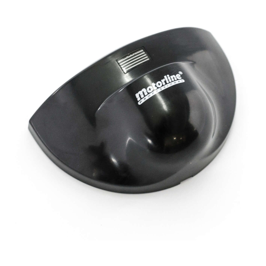
Detector
CHARACTERISTICS BOARD
• Technology
• Transmission frequency
• Transmission power
• Transmission Density
• Maximum installation height
• Installation angles
• Detection zone (Mounting Height: 2.2m)
• Detection type
• Minimum speed
• Power Supply
• Frequency
• Consumption
• Pause time
• Working temperature
• Protection degree
• Standards
• Material
• Colour
• Dimensions
• Weight
• Cable length
• Contact maximum voltage
• Contact maximum current
• Maximum power
• SPECIAL CARE DURING INSTALLATION
01. Fix the radar firmly in order to avoid vibrations.
02. Do not cover or block the sensor's field of action.
03. Avoid placing moving objects in sensor proximity.
04. Avoid fluorescent lamps near the sensor.
05. Avoid touching the electronic components.
06. Turn the potentiometer slowly and without forcing.
12~24V AC/DC (-/+10%)
Relay
65mA
130mA
3500mm
vertical: 00 to 900 | lateral: -300 to 300
6m (W) x 3m (D)
Movement
5cm/s
12V to 24V AC/DC +30% /-10%
50 to 60Hz
<2W (VA)
1.0sec
-250C to 550C
IP54
R&TTE 1999/5/EC; EMC89/336/EEC
ABS
Black
120 x 80 x 50 mm
0.265kg
2500mm
RELAY OUTPUT
42V AC - 60V DC
1A (resistive)
30W (DC) / 60VA (AC)
V2.0
REV. 06/2016
EN
Advertisement
Table of Contents

Summary of Contents for Motorline professional M1601
- Page 1 M1601 | V2.0 USER'S AND INSTALLER'S MANUAL REV. 06/2016 TECHNICAL SPECIFICATIONS CHARACTERISTICS BOARD • Technology 12~24V AC/DC (-/+10%) • Transmission frequency Relay • Transmission power 65mA • Transmission Density 130mA • Maximum installation height 3500mm • Installation angles vertical: 00 to 900 | lateral: -300 to 300 •...
- Page 2 M1601 | USER'S AND INSTALLER'S MANUAL RADAR INSTALLATION ADJUSTMENTS • INSTALLATION • SENSITIVITY AND RANGE ADJUSTMENTS Adjusting the sensitivity determines the operation area: Alignment between radar and safe. Vertical angle : 300 01. Place the radar centered with the safe's cover 02.


Need help?
Do you have a question about the M1601 and is the answer not in the manual?
Questions and answers