Table of Contents
Advertisement
Instruction Manual
This instruction manual is intended to be a guide when operating the 112 Extreme Seam welder. To
ensure optimal performance from your welder, please follow the recommendations and specifications
precisely.
For more technical information regarding this machine call our Resolution Center at 1-855-888-WELD or
email service@weldmaster.com.
You can also subscribe to Miller Weldmaster Insiders to stay updated on tech tips, machine maintenance
updates, and more at www.weldmaster.com/insiders.
330.833.6739
www.weldmaster.com
Page 1
Advertisement
Table of Contents

Related Manuals for Miller Weldmaster 112 Extreme


Summary of Contents for Miller Weldmaster 112 Extreme
- Page 1 Instruction Manual This instruction manual is intended to be a guide when operating the 112 Extreme Seam welder. To ensure optimal performance from your welder, please follow the recommendations and specifications precisely. For more technical information regarding this machine call our Resolution Center at 1-855-888-WELD or email service@weldmaster.com.
-
Page 2: Table Of Contents
Instruction Manual Table of Contents Chapter 1: Intended Use Page 3 Chapter 2: Explanation of Warnings Pages 4-5 Chapter 3: Electrical and Air Requirements Page 6 Chapter 4: Principles of Heat Sealing Page 7 Chapter 5: Definition of Controls Pages 8-14 Chapter 6: Recommended Replacement Parts Page 15 Chapter 7: Adjustments... -
Page 3: Chapter 1: Intended Use
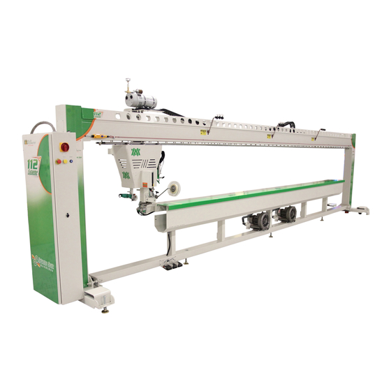
Instruction Manual Intended Use The 112 is a rotary hot air welding machine intended to heat-seal weldable thermal plastics such as: •Vinyl (PVC) laminated and coated fabrics •Vinyl (PVC) and Polyurethane (PU) films •Polyurethane (PU) and Polypropylene (PP) coated fabric •Polyethylene (PE) •Thermoplastic rubber (TPR) film and fabrics •Non-woven Polyester and Polypropylene... -
Page 4: Chapter 2: Explanation Of Warnings
Instruction Manual Explanation of Warnings There are several different warning symbols placed on the Miller Weldmaster 112. The symbols are to alert the operator of potentially hazardous areas on the machine. Familiarize yourself with their placement and meaning. Caution: Laser Radiation Do not stare into beam or view directly with optical instruments. - Page 5 Instruction Manual Explanation of Warnings Warning: Keep Hands Clear The“Warning: Keep Hands Clear” sticker is placed on the Heater Assembly. To prevent any pinching or burns, be aware of the location of your hands at all times. Warning: High Temperature Air The “Warning: High Temperature Air”...
-
Page 6: Chapter 3: Electrical And Air Requirements
•50 Amperes - 3 phases - 400 Volts Shop Air Supply The Miller Weldmaster 112 Extreme includes an In-Shop Air Supply Valve that allows quick connects and disconnects to your shop air supply. Due to the number of different style airline connectors, a male quick-connect is not included. -
Page 7: Chapter 4: Principles Of Heat Sealing
Instruction Manual Principals of Heat Sealing Heat: The Heat required for the welding operation is created electrically by two heating elements located inside the Heat Element Housing. The Internal Air Compressor pumps air over the heat elements and carries the heat through the Hot Air Nozzle, applying the heat to the material to be welded. -
Page 8: Chapter 5: Definition Of Controls
Instruction Manual Definition of Controls Main Menu 1. Alarms: The alarm button will take the operator to the alarm screen. This allows a technician to see any alarms the 112 Extreme may have encountered. 2. Maintenance Configuration: The Maintenance Configuration button will take the operator to the Maintenance Configuration screen. - Page 9 Machine Speed: The purpose of Machine Speed is to control the speed of the carriage assembly during the welding process. The machine speed number is a percentage of how fast the 112 extreme head carriage will run. Note: To convert to feet per minute or meter per minute, go to help page under Speed Chart.
- Page 10 Instruction Manual Definition of Controls Weld Roller: The purpose of this function is to lift the weld roller up or down. Main: The function of this is to take the operator to the Main Menu. Recipe: The function of this is to take the operator to the recipe page to allow the operator to change seams or the option to go to the Recipe Management screen.
- Page 11 Instruction Manual Definition of Controls Operator Configuration: In this screen, the operator has control over different configurations. 1. Temperature Notification: When this is selected, the 112 Extreme will notify the operator to check nozzle placement when the temperature controller is changed+/- 160 F. 2.
- Page 12 This setting is resettable every time the elements are changed by pressing and holding the heat system reset time in. 4. Time Totalizer: The purpose of the time totalizer is to monitor the hours of use on the 112 extreme. CHAPTER 5 DEFINITION OF CONTROLS...
- Page 13 Instruction Manual Definition of Controls Maint Configuration This screen is accessed with a password and is very similar to the operator configurations. The difference is this screen under the head 1 setting allows the operator to adjust the temperature controller and auto tune the temperature controller. Main: By selecting this the operator will be taken to the main- screen.
- Page 14 Instruction Manual Definition of Controls Language Selection Choose what language the operator wants to use. Example: (Press English to run machine in English). Language: Press this button to choose different languages of which the machine can be run. Active Alarms This screen shows the operator the alarm that faulted out the machine.
-
Page 15: Chapter 6: Recommended Replacement Parts
Instruction Manual Recommended Replacement Parts Miller Weldmaster recommends keeping the following spare parts in stock: NOTE: The manufacturer will not be held liable for any damage or injuries occurring from any inappropriate use of this machine. Page 15 CHAPTER 6 RECOMMENDED REPLACEMENT PARTS... -
Page 16: Chapter 7: Adjustments
Instruction Manual Adjustments Nozzle Adjustment Nozzle placement is a key component in heat sealing. A properly-placed nozzle will be centered on the weld roller approximately ¼-inch away and have a slight whistle during the welding process. When an adjustment is needed, turn the speed control to a low setting. - Page 17 Instruction Manual Adjustments Warning! When adjusting the lasers, do not look directly into the laser source. Use caution when calibrating lasers. Laser Alignment Double Laser Line 1.Turn the POWER on. 2. Leave the Heat Switch in the OFF position. Load some sample fabric (white is best) under the fabric clamp and extend to the end of the machine.
- Page 18 Instruction Manual Adjustments Guide Adjustments Welding a Hem: The hem guide needs to be 1/16 to 1/8inch off track and aligned perpendicular to track. The outside of guide needs to be adjusted to outside of weld roller. After running a test if there is a pocket on the hem move guide away from operator.
- Page 19 Instruction Manual Adjustments Welding a Hem with Rope: Welding a hem with rope is the same as welding a straight hem except you are adding rope through the rope eyelet or leaving a void for the open pocket. 1. Install hem and rope guide. 2.
- Page 20 Instruction Manual Adjustments Welding an Overlap •The overlap guide needs to be high enough so the nozzle can swing in and not hit the bottom of the guide. The guide also needs to be perpendicular to the track. •The overlap guide is used to control the exact positioning of the top fabric panel being welded.
- Page 21 Instruction Manual Adjustments Welding a Pole Pocket •The pocket guide needs to be high enough so the nozzle does not hit the bottom of the guide. It also needs to be perpendicular to the track. •The pocket guide is used to weld pole pockets. The guide is used to control the exact positioning of the top flap of material.
- Page 22 Instruction Manual Adjustments Welding Webbings or Tapes 1. Install the adjustable webbing or tape guide to the machine. 2. Adjust the guide to the correct width of your webbing or tape. 3. Insure that the weld roller and nozzle will not touch the guide. The guide also needs adjusted parallel to the wheel.
- Page 23 Instruction Manual Adjustments Interchanging of Weld Rollers 1. Loosen the bolt on the weld roller clamping collar. 2. Slide the weld roller off of the weld roller shaft. 3. Slide the new weld roller on to the weld roller shaft. a.
- Page 24 Instruction Manual Adjustments Weld Roller Cylinder Adjustment •The pressure on the weld roller is created from the pneumatic cylinder used to pick up or put down the weld roller. •The pressure on the weld roller is regulated and displayed on the control panel. The pressure needs to be set at least at 10lbs.
- Page 25 Adjustments Micro-Switch Adjustments This page will detail each of the Micro-switches and sensors on the Miller Weldmaster 112 Extreme. •Overrun Limit Switch: The purpose of this switch is to stop the head carriage from over travel. *Note: This switch will initiate the Emergency Stop and take power and air from the machine.
-
Page 26: Chapter 8: Maintenance
Cleaning •Air Filter Cartridge: The Miller Weldmaster 112 Extreme has an Air Compressor that supplies airflow to the heat elements. Periodic cleaning and changing of the Air Filter Cartridge is necessary to maintain sufficient airflow. Insufficient airflow or any impurities in the airflow will shorten the life of the heat elements. - Page 27 Replacing Components •Heat Elements: The Heating Elements used by the Miller Weldmaster 112 Extreme are rated for 1000 hours of use at 537 degrees Celsius (1000 degrees F). Although longer heat element life is possible with proper maintenance; 1000 hours is the average. If the Heat Elements fail prematurely, contact a Miller Weldmaster representative before replacement.
- Page 28 Instruction Manual Maintenance Replacing Components Cont.. Warning! Inspect each element for any broken-off fragments of glass or wire. Any missing fragments will be in the dual-element housing or nozzle. These fragments must be removed before installing new elements. 12. Carefully install 2 new heat elements into the Dual-Element Housing. 13.
- Page 29 Maintenance Replacing Components •Thermocouple: The Miller Weldmaster 112 Extreme uses a Thermocouple to read the air temperature just before it reaches the nozzle. The typical life expectancy of a Thermocouple varies. The Thermocouple should be replaced if the machine does not maintain a constant temperature of +/- 1 Degree C ( +/- 2 Degrees F) or the heat elements burn out prematurely.
-
Page 30: Chapter 9: Transportation Specs And Storage
Transporting Within a Production Facility Due to the weight of the Miller Weldmaster machine, the manufacturer requires a forklift or tow motor to be used. The forks are to be inserted below the bottom frame of the upper beam along the center of gravity. -
Page 31: Chapter 10: Troubleshooting
Instruction Manual 10.0 Troubleshooting NOTE: The machine must have at least 90psi of air pressure in order to Reset power. Loss of Welding Temperature -Heat elements may be burned out, check number of hours on the heat elements. The heat elements are rated for 1000 hours at 730C. -Thermocouple may be burned out or loose wires. - Page 32 Instruction Manual 10.0 Troubleshooting Seam is Only Welded on One Side •The hot air nozzle tip needs to be adjusted. -Nozzle needs adjusted side to side. -Nozzle may be pinched shut on one side. Open the pinched side so there is even flow. -The speed control is set too high not allowing enough time for the hot air to be applied to the seam properly.
- Page 33 Instruction Manual 10.0 Troubleshooting •Hem is over puckering or burnt one side out. -Temperature is too hot. Turn heat down or speed up the machine. •Hem will not stay in guide. -Guide not square, adjust guide. -Add clutch pressure. •Nozzle hits material. -Nozzle too high.
- Page 34 Instruction Manual 10.0 Troubleshooting Butt Seam •Tape not centered in weld. -Guide misaligned. -Center of butt not aligned with laser. -Laser line not centered with weld roller. •Tape wrinkling. -Too much clutch pressure. -Too hot. Truck Side Beading •Indicator line does not line up with material. -Guide misaligned.
- Page 35 Instruction Manual NOTES:_________________________________________________________________ _______________________________________________________________________ _______________________________________________________________________ _______________________________________________________________________ _______________________________________________________________________ _______________________________________________________________________ _______________________________________________________________________ _______________________________________________________________________ _______________________________________________________________________ ______________________________________________________________________ _______________________________________________________________________ _______________________________________________________________________ _______________________________________________________________________ _______________________________________________________________________ _______________________________________________________________________ _______________________________________________________________________ Page 35 NOTES...
- Page 36 Instruction Manual NOTES:_________________________________________________________________ NOTES:_________________________________________________________________ _______________________________________________________________________ _______________________________________________________________________ _______________________________________________________________________ _______________________________________________________________________ _______________________________________________________________________ _______________________________________________________________________ _______________________________________________________________________ _______________________________________________________________________ _______________________________________________________________________ _______________________________________________________________________ _______________________________________________________________________ _______________________________________________________________________ _______________________________________________________________________ _______________________________________________________________________ _______________________________________________________________________ _______________________________________________________________________ ______________________________________________________________________ ______________________________________________________________________ _______________________________________________________________________ _______________________________________________________________________ _______________________________________________________________________ _______________________________________________________________________ _______________________________________________________________________ _______________________________________________________________________ _______________________________________________________________________ _______________________________________________________________________ _______________________________________________________________________ _______________________________________________________________________ _______________________________________________________________________ _______________________________________________________________________ NOTES Page 36...
- Page 37 Instruction Manual NOTES:_________________________________________________________________ _______________________________________________________________________ _______________________________________________________________________ _______________________________________________________________________ _______________________________________________________________________ _______________________________________________________________________ _______________________________________________________________________ _______________________________________________________________________ _______________________________________________________________________ ______________________________________________________________________ _______________________________________________________________________ _______________________________________________________________________ _______________________________________________________________________ _______________________________________________________________________ _______________________________________________________________________ _______________________________________________________________________ Page 37 NOTES...
Need help?
Do you have a question about the 112 Extreme and is the answer not in the manual?
Questions and answers