Table of Contents
Advertisement
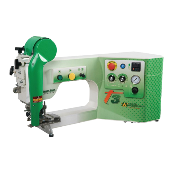
Instruction Manual
This instruction manual is intended to be a guide when operating the T3 Extreme Seam welder. To ensure opti-
mal performance from your welder, please follow the recommendations and specifications precisely.
For more technical information regarding this machine call our Resolution Center at 1-855-888-WELD or email
service@weldmaster.com.
You can also subscribe to Miller Weldmaster Insiders to stay updated on tech tips, machine maintenance up-
dates, and more at www.weldmaster.com/insiders.
Page 1
Advertisement
Table of Contents

Related Manuals for Miller Weldmaster T3 Extreme


Summary of Contents for Miller Weldmaster T3 Extreme
- Page 1 Instruction Manual This instruction manual is intended to be a guide when operating the T3 Extreme Seam welder. To ensure opti- mal performance from your welder, please follow the recommendations and specifications precisely. For more technical information regarding this machine call our Resolution Center at 1-855-888-WELD or email service@weldmaster.com.
-
Page 2: Table Of Contents
Instruction Manual Table of Contents Chapter 1: Intended Use Page 3 Chapter 2: Explanation of Warnings Pages 4 Chapter 3: Electrical and Air Requirements Page 5 Chapter 4: Principles of Heat Sealing Page 6 Chapter 5: Definition of Controls Page 7-11 Chapter 6: Operation Page 12 Chapter 7: Adjustment... -
Page 3: Chapter 1: Intended Use
Instruction Manual Intended Use The T3 is a rotary hot wedge welding machine intended to heat-seal weldable thermal plastics such as: •Vinyl (PVC) laminated and coated fabrics •Vinyl (PVC) and Polyurethane (PU) films •Polyurethane (PU) and Polypropylene (PP) coated fabric •Polyethylene (PE) •Thermoplastic rubber (TPR) film and fabrics •Non-woven Polyester and Polypropylene... -
Page 4: Chapter 2: Explanation Of Warnings
Instruction Manual Explanation of Warnings There are several different warning symbols placed on the Miller Weldmaster T3. The symbols are to alert the operator of potentially hazardous areas on the machine. Familiarize yourself with their placement and meaning. Caution: Unplug Machine The “Caution: Unplug Machine”... -
Page 5: Chapter 3: Electrical And Air Requirements
•16 Amperes - Single phase - 230 Volts Shop Air Supply The Miller Weldmaster T-3 includes an in-shop air supply valve that allows quick connects and disconnects to your shop air supply. Due to the number of different style airline connectors, a male quick-connect is not included. - Page 6 Instruction Manual Principals of Heat Sealing Heat Hot Air Heating System The Heat required for the welding operation is created electrically by one heating element located inside the Heat Element Housing. The Internal Air Compressor pumps air over the heat element and carries the heat through the Hot Air Nozzle, applying the heat to the material to be welded.
-
Page 7: Chapter 5: Definition Of Controls
Instruction Manual Definition of Controls The manufacturer suggests that all operators are familiar with all the controls of their machine. It is in the operators best interest to know the purpose of all these controls and their functions. Start Button: The start button initiates the wedge swing and motor controls. - Page 8 Instruction Manual Definition of Controls Emergency Stop Button: The emergency stop button will stop the system operations in the event of an emergency. Depress the emergency stop button in the event of an emergency. Twist to release the emergency stop button. Reset Button: The reset button turns power ON to the control system of the machine.
- Page 9 Instruction Manual Definition of Controls Pressure Gauge and Regulator: The pressure gauge and regulator displays and controls the weld roller pressure. To increase or decrease the weld roller pressure, pull the regulator knob out then rotate. Rotate clockwise to increase the pressure and counter clockwise to decrease the pressure.
- Page 10 Instruction Manual Definition of Controls Power Disconnect: The power disconnect turns power ON/ OFF to the machine. For power to be turned ON rotate the handle to the ON position and to turn OFF turn to the OFF position. The power disconnect should always be turned OFF when the machine is not in use or being serviced.
-
Page 11: Chapter 6: Operation
Instruction Manual Operation NOTE: Before starting up the machine, please check it carefully and guarantee that there are no foreign objects under the welding area. Be sure the surrounding area of the machine is free of flammable debris. Only authorized persons are permitted to use machine. Start Up 1. -
Page 12: Chapter 7: Adjustment
Instruction Manual Adjustments Wedge Adjustment Wedge placement is the most important component with wedge welding. When the wedge arm swings in and drives forward, it is imperative that the point of the alignment pin fits into the recess of the wedge arm. Before adjusting the wedge system be sure the weld roller pressure is set to the desired pressure setting. - Page 13 Instruction Manual Adjustments Wedge Squareness Alignment Before checking the wedge alignment, set the speed control to its lowest setting, the drive delay to its highest setting, and close the weld rollers. 1. Swing the wedge into place by depressing the drive foot pedal or the start button.
- Page 14 Instruction Manual Adjustments Wedge Tilt Alignment Before checking the wedge alignment, set the speed control to its lowest setting, the drive delay to its highest setting, and close the weld rollers. 1. Swing the wedge into place by depressing the drive foot pedal or the start button.
- Page 15 Instruction Manual Adjustments Wedge Left/Right Alignment Before checking the wedge alignment, set the speed control to its lowest setting, the drive delay to its highest setting, and close the weld rollers. 1. Swing the wedge into place by depressing the drive foot pedal or the start button.
- Page 16 Instruction Manual Adjustments Wedge Depth Alignment Before checking the wedge alignment, set the speed control to its lowest setting, the drive delay to its highest setting, and close the weld rollers. 1. Swing the wedge into place by depressing the drive foot pedal or the start button.
-
Page 17: Chapter 8: Welding Tips
Instruction Manual Welding Tips Bad Weld (Fig. 01) This is not a good weld. Although the fabric is somewhat welded, it is not what could be considered 100%. One of two things must happen for this weld to become accepted. Either the speed must be decreased or the heat must be increased. - Page 18 Instruction Manual Welding Tips Uneven Fabric Tension (Fig. 04) This is an example of too much tension held on the bottom fabric panel. It is important for the operator to hold even (equal) tension on both the top and bottom fabric panels as the machine is welding.
-
Page 19: Chapter 9: Accessories
Instruction Manual Accessories Guides The Miller Weldmaster T3 gives the user the ability to switch from one application to the next with our quick change guides. Page 19 CHAPTER 8 WELDING TIPS... -
Page 20: Chapter 10: Maintenance
10.0 Maintenance The Miller Weldmaster T3 has certain items that need maintained to keep the machine running as effective as possible. The T3 has three chains which are used to drive the weld rollers and travel roller on the machine. Although not high maintenance items, chains should be inspected every 3 months to ensure there is not excessive corrosion, rust, or dirt. - Page 21 - When tightening the bolts onto the rear mounting bracket, loosen by a 1/8 of a turn so the wedge has some float in it. 6. Contact a Miller Weldmaster service representative with any questions or to discuss an area of uncertainty.
-
Page 22: Chapter 12: Transportation And Storage
Transportation Outside a Production Facility The manufacturer requires the Miller Weldmaster machine to be placed on a pallet and loaded into a truck using a forklift or tow motor. The forks are to be inserted below the bottom frame along the center of gravity. Before lifting the machine be sure to secure all components. - Page 23 Instruction Manual NOTES:_________________________________________________________________ _______________________________________________________________________ _______________________________________________________________________ _______________________________________________________________________ _______________________________________________________________________ _______________________________________________________________________ _______________________________________________________________________ _______________________________________________________________________ _______________________________________________________________________ ______________________________________________________________________ _______________________________________________________________________ _______________________________________________________________________ _______________________________________________________________________ _______________________________________________________________________ _______________________________________________________________________ _______________________________________________________________________ Page 23 CHAPTER 11 RECOMMENDED REPLACEMENT PARTS...
- Page 24 Instruction Manual NOTES:_________________________________________________________________ _______________________________________________________________________ _______________________________________________________________________ _______________________________________________________________________ _______________________________________________________________________ _______________________________________________________________________ _______________________________________________________________________ _______________________________________________________________________ _______________________________________________________________________ ______________________________________________________________________ _______________________________________________________________________ _______________________________________________________________________ _______________________________________________________________________ _______________________________________________________________________ _______________________________________________________________________ _______________________________________________________________________ CHAPTER 12 TRANSPORTATION AND STORAGE Page 24...
- Page 25 Instruction Manual NOTES:_________________________________________________________________ _______________________________________________________________________ _______________________________________________________________________ _______________________________________________________________________ _______________________________________________________________________ _______________________________________________________________________ _______________________________________________________________________ _______________________________________________________________________ _______________________________________________________________________ ______________________________________________________________________ _______________________________________________________________________ _______________________________________________________________________ _______________________________________________________________________ _______________________________________________________________________ _______________________________________________________________________ _______________________________________________________________________ Page 25 NOTES...
Need help?
Do you have a question about the T3 Extreme and is the answer not in the manual?
Questions and answers