Advertisement
Table of Contents
I NSTA LLAT ION G UI DE
HID Aero™ X100
Reader Interface
Up to 4 Readers, 7 Inputs, 4 Outputs
Supplied parts
ƒ HID Aero X100 reader interface (1)
ƒ Installation guide (1)
ƒ Mounting screws (4) 0.138" × 1" (3.5 mm × 25 mm)
Recommended parts
(not supplied)
ƒ Certified DC power supply
ƒ Drill with various bits for mounting hardware
ƒ For DIN rail mounting: Brackets (2) - Phoenix Contact,
USA 10 Series Rail Adapter, part number 1201578.
Screws (4) - Self tapping, countersunk,
3.0 mm × 10 mm (or 3.0 mm × 8 mm)
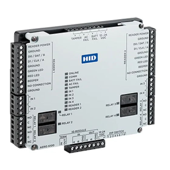
X100 Overview
The X100 has two reader ports, four relays, seven inputs, and one RS-485 port for IO module connection.
Status LEDs
See page 6
READERS 1-2
See step 3.
"
4.53
(115 mm)
INPUTS 1-4
See step 4.
RELAYS 1-4
See step 5.
JUMPERS
See step 2.
© 2019 - 2020 HID Global Corporation/ASSA ABLOY AB. All rights reserved. HID, the HID Brick logo, the Chain Design, HID Aero, and HID Signo are trademarks or registered
trademarks of HID Global, ASSA ABLOY AB, or its affiliate(s) in the US and other countries and may not be used without permission. All other trademarks, service marks, and
product or service names are trademarks or registered trademarks of their respective owners.
hi d gl ob a l.com
CABLE REQUIREMENTS (NOT SUPPLIED)
Readers - OSDP
Readers -
Wiegand / C&D
IO Module
Alarm Inputs
Power and Relays
POWER, TAMPER, AC FAIL, BATT FAIL
See step 7.
"
5.51
(140 mm)
An ASSA ABLOY Group brand
PLT-04234, Rev. A.3
4 conductor twisted pair over-all
shield, Belden 3107A or equivalent.
2000 ft (610 m) maximum. Utilize one
pair for data and one pair for power
4-conductor, 18 AWG, shielded, 500 ft
(150 m) maximum
One twisted pair, shielded, 24 AWG,
120Ω impedance, 4,000 ft
(1,219 m) maximum
One twisted pair per input,
30Ω maximum, typically 22 AWG,
1000 ft (304.8 m)
2-conductor shielded
18 to 16 AWG, 500 ft (150 m)
Status LEDs
See page 6
READERS 1-2
See step 3.
INPUTS 1-4
See step 4.
RELAYS 1-4
See step 5.
DIP SWITCH
See step 6.
IO MODULE PORT
See step 2.
Advertisement
Table of Contents

Related Manuals for HID Aero X100

Summary of Contents for HID Aero X100
-
Page 1: Table Of Contents
(140 mm) © 2019 - 2020 HID Global Corporation/ASSA ABLOY AB. All rights reserved. HID, the HID Brick logo, the Chain Design, HID Aero, and HID Signo are trademarks or registered trademarks of HID Global, ASSA ABLOY AB, or its affiliate(s) in the US and other countries and may not be used without permission. All other trademarks, service marks, and product or service names are trademarks or registered trademarks of their respective owners. -
Page 2: See
Powering Trusted Identities HID Aero™ X100 Installation Guide Mounting the X100 ATTENTION Observe precautions for handling ELECTROSTATIC SENSITIVE DEVICES ƒ Always mount the controllers and interface panels in a secure area. ƒ Mount using the supplied screws 0.138" × 1"... -
Page 3: Readers
Powering Trusted Identities HID Aero™ X100 Installation Guide Connecting readers ƒ OSDP (RS-485) signaling requires two 2-conductor Note: For OSDP cable lengths greater than 200 ft (61 m) or EMF interference, install 120Ω +/- 2Ω resistor cables. One cable for power (18 AWG) and one across RS-485 termination ends. -
Page 4: Relays
Powering Trusted Identities HID Aero™ X100 Installation Guide Input circuit wiring Unsupervised circuit IN 1 to IN 4 Inputs are typically used for the following: ƒ To monitor door position. ƒ Request to exit. ƒ Alarm contacts. Input IN 1 to IN 4 circuits can be configured as... - Page 5 Powering Trusted Identities HID Aero™ X100 Installation Guide DIP switch configuration Switches 1 through 5 select the device address. Switches 6 and 7 select the communication baud rate. Switch 8 is not in use. SELECTION Address 0 Address 1 Address 2...
- Page 6 Powering Trusted Identities HID Aero™ X100 Installation Guide Input power, cabinet tamper, and UPS fault input wiring Connect the AC FAIL and BATT FAIL inputs to the The X100 requires 12-24 V DC power. Connect power with minimum of 18 AWG wire.
-
Page 7: Readers
Powering Trusted Identities HID Aero™ X100 Installation Guide Specifications HID AERO X100 Input Voltage 12 to 24 V DC ±10% Maximum Input Current 1.5 A (340 mA excluding readers) 2-wire RS-485, 2,400 to 115,200 bps, asynchronous, IO Module half-duplex, 1 start bit, 8 data bits, and 1 stop bit Seven unsupervised/supervised, standard EOL: 1k/1kΩ, 1%, ¼... - Page 8 ると電波妨害を引き起こすことがあります。この場合には使用者が適切な 時,可能會造成射頻干擾,在這種情況下, 対策を講ずるよう要求されることがあります。VCCI -A 伊用者會被要求採取某些適嘗的酎策。 Your HID product is marked to indicate its compliance class: ƒ Federal Communications Commission (FCC) – USA ƒ Industry Canada Equipment Standard for Digital Equipment (ICES-003) – Canada ƒ CE Mark – Europe ƒ RCM Mark – New Zealand and Australia ƒ...
Need help?
Do you have a question about the Aero X100 and is the answer not in the manual?
Questions and answers
Programming and wireing digram
The HID Aero X100 does not provide a full programming and wiring diagram in the provided context. However, the following wiring information is available:
1. Input Circuit Wiring (IN 1 to IN 4):
- Used for monitoring door position, request to exit, and alarm contacts.
- Can be configured as unsupervised or supervised.
- Unsupervised: Uses normally open or normally closed contacts directly.
- Supervised: Requires two 1KΩ, 1% resistors placed close to the sensor. Custom EOL resistances can be configured via host software.
2. Relay Circuit Wiring (RELAY 1 to RELAY 4):
- Used for door lock mechanisms or alarms.
- Use the NO (Normally Open) and C (Common) terminals.
- DC power source and fuse required in the circuit.
3. Cable Requirements:
- Power cable: 18 AWG.
- Communication cable: 24 AWG shielded twisted pair for RS-485.
- Wiegand or Clock/Data signaling: 4-conductor 18 AWG shielded cable.
- Optional conductors for LED and beeper control.
4. RS-485 Termination:
- For cables longer than 200 ft (61 m), install a 120Ω ±2Ω resistor across RS-485 termination ends.
5. Power Source:
- Must be from a UL294 certified limited power source.
- Follow NFPA70 and local codes.
No specific programming diagram is included in the provided content.
This answer is automatically generated