
Subscribe to Our Youtube Channel
Related Manuals for IFM Electronic AC2729


Summary of Contents for IFM Electronic AC2729
- Page 1 Betriebsanleitung Operating instructions Notice d’utilisation AC2729 AS-i Platine AS-i PCB Circuit imprimé AS-i...
-
Page 2: Bestimmungsgemäße Verwendung
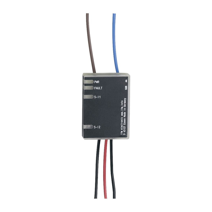
Bestimmungsgemäße Verwendung Die AS-i Platine erfasst bis zu zwei nicht sichere Schaltzustände, z. B. 1- oder 2-kanalige mechanische Kontakte. Montage Montieren Sie die AS-i Platine an einem geschützten Ort (z. B. Schalt- schrank, Aufbaugehäuse). Das geeignete Gehäuse muss eine Schutzart von mindestens IP 54 aufweisen. Führen Sie nach dem Ein- bau der AS-i Platine einen Inbetriebnahmetest durch. - Page 3 Anschlussbelegung AS-i + AS-i - I1-1/I1-2 I2-1/I2-2: Schalteingang mechanischer Kontakt I1 / I2 LEDs 1: Schaltzustandsanzeige Eingänge I1, I2 LEDs 2: AS-i, FAULT X1-X2: externer LED-Ausgang Datenbits Datenbit In/Out I-1/O-1 Adressieren Die Platine kann über das Adressiergerät AC1144 mit Hilfe des Kabels (E70032) im montierten und verdrahtetem Zustand adressiert werden.
-
Page 4: Betrieb
Betrieb Prüfen Sie, ob das Gerät sicher funktioniert. Anzeige durch LEDs: • LEDs 1 gelb: Eingänge geschaltet (I1, I2) • LED 2 grün: Spannungsversorgung o.k. (PWR) • LED 2 rot leuchtet: AS-i Kommunikationsfehler, Slave nimmt nicht am „normalen“ Datenverkehr teil, z. B. Slaveadresse 0 (FAULT) •... -
Page 5: Function And Features
Function and features The AS-i PCB detects up to two unsafe switching states, e.g. 1 or 2- channel mechanical contacts. Mounting Install the AS-i PCB in a protected location (e. g. control cabinet, hous- ing). The appropriate housing must have a protection rating of at least IP 54. - Page 6 Wiring AS-i + AS-i - I1-1/I1-2 I2-1/I2-2: switching input mechanical contact I1 / I2 LEDs 1: switching status indication inputs I1, I2 LEDs 2: AS-i, FAULT X1-X2: external LED output Data bits Data bit In/Out I-1/O-1 Addressing When mounted and wired the PCB can be addressed via the address- ing unit AC1144 using the cable (E70032).
-
Page 7: Operation
Operation Check the reliable functioning of the unit. LED display: • LEDs 1 yellow: inputs switched (I1, I2) • LED 2 green: voltage supply ok (PWR) • LED 2 red lights: AS-i communication error, slave does not participate in the “normal“ exchange of data, e.g. -
Page 8: Fonctionnement Et Caractéristiques
Fonctionnement et caractéristiques Le circuit imprimé AS-i détecte jusqu’à deux états de commutation non sécurité, par ex. des contacts mécaniques à une ou deux voies. Montage Le circuit imprimé AS-i doit être monté dans un lieu protégé (par ex. armoire électrique, boîtier). Le boîtier approprié doit avoir un indice de protection d’au moins IP 54. - Page 9 Schéma de branchement A+ : AS-i + A- : AS-i - I1-1/I1-2 I2-1/I2-2 : entrée de commutation contact mécanique I1 / I2 LED 1 : indication de commutation entrées I1, I2 LED 2 : AS-i, FAULT X1-X2 : sortie LED externe Bits de données Bit de donnée In/Out...
-
Page 10: Données Techniques
Fonctionnement Vérifier le bon fonctionnement de l’appareil. Affichage par LED : • LED 1 jaunes : entrées commutées (I1, I2) • LED 2 verte : alimentation en tension ok (PWR) • LED 2 rouge allumée : erreur de communication AS-i, l’esclave ne participe pas à...
Need help?
Do you have a question about the AC2729 and is the answer not in the manual?
Questions and answers