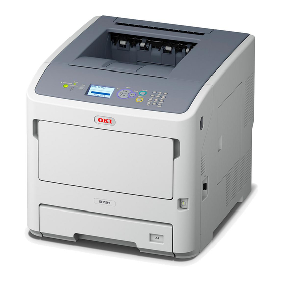
Oki B721DN Instructions Manual
Right side paper tray guide replacement
Hide thumbs
Also See for B721DN:
- Safety information manual (48 pages) ,
- Maintenance manual (9 pages) ,
- Accessory installation manual (8 pages)
Advertisement
Table of Contents
B721DN Right Side Paper Tray Guide
The symptoms are constant paper jams or the paper tray will not lock in place or will pop out.
If you have to replace the Right Side Paper Tray Guide due to breakage, you should order Oki Data Part
Number: 45373501, which is the entire right side frame assembly as shown below:
Rather than removing and replace the entire right side frame, you can remove the Right Side Paper Tray
Guide by removing the 2 screws highlighted above and performing the procedure on the next pages for
replacement of the right side paper tray guide on a customer's machine.
Screws are indicated by
NOTE:
Tabs are indicated by
Cables / Connectors are indicated by
Red
callouts
Blue
callouts
Green
Replacement
callouts
Advertisement
Table of Contents

Summary of Contents for Oki B721DN
- Page 1 The symptoms are constant paper jams or the paper tray will not lock in place or will pop out. If you have to replace the Right Side Paper Tray Guide due to breakage, you should order Oki Data Part Number: 45373501, which is the entire right side frame assembly as shown below:...
- Page 2 Step Procedure Photo a.) Unplug the B721DN power cord from the wall. b.) Remove the Paper Cassette from the printer c.) Open the front and top cover and remove the Drum and Toner assembly. Remove 3 screws from the upper right side cover.
- Page 3 Open the rear paper path door There are 3 tabs holding the right side cover at the rear of the printer. Gently release all 3 tabs as described below: 2 of them are shown at right. The third tab is located above the straight through paper path door.
- Page 4 Three along the upper side of the right cover Now, gently lift and remove the right side cover from the printer. There are 8 screws on the metal shield plate to be removed. 1 on the top of the shield 2 on the rear of the shield 5 on the face of the shield At the front of the metal shield, gently lift...
- Page 5 Remove three Power Connectors (Green boxes) and 4 Screws from the Low Voltage Power Supply. Remove the Low Voltage Power Supply. Remove the black plastic shield that is behind the Low Voltage Power Supply Gently unplug the Ribbon Cables (Green boxes) from the printer’s logic board and carefully unthread the ribbon cable through the printer.
- Page 6 Gently unplug the wire connector from the paper tray connector in the bottom of the frame Unplug the red 2 wire connector Remove the screw securing the grounding wire from the front tray to the printer chassis and unthread the grounding wire. Remove the screw securing the bottom frame bracket on the right side of the printer.
- Page 7 Remove the screw from the right Front Cover Stay and disconnect the right hinge arm. Remove the 3 screws from the right Front Hinge assembly and remove the hinge assembly. The right side of the front cover is not disconnected from the right side cassette tray guide.
- Page 8 Remove the bottom frame bracket from the right side cassette guide. Remove the right side cassette guide. Reassemble the printer by following the disassembly guide in reverse. CAUTION : Rethread the cables in Steps 16, 17, 20 & 24 as they were originally threaded.


Need help?
Do you have a question about the B721DN and is the answer not in the manual?
Questions and answers