Table of Contents
Advertisement
Quick Links
ArrayJ
USER MANUAL
ArrayJ - High Fill-Factor Arrays of J-Series SiPM Sensors
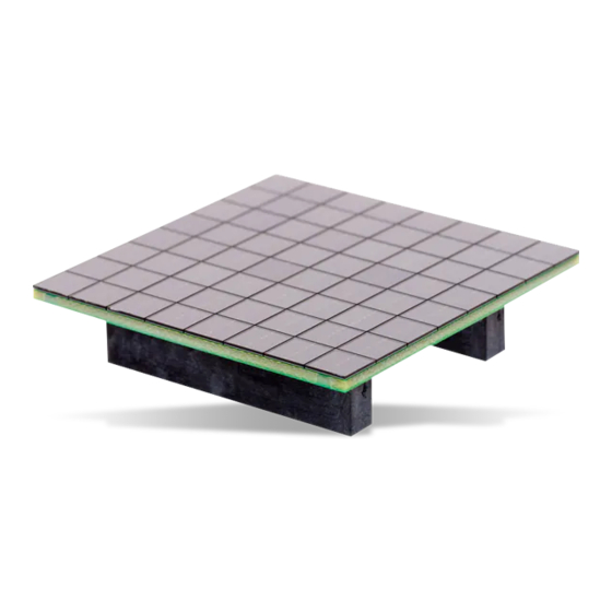
SensL's range of J-Series SiPM sensors have been used
to create high fill-factor, scaleable arrays. The sensors are
mounted onto PCB boards with minimal dead space, forming
arrays with industry-leading fill factor of up to 90%.
The back of each ArrayJ has either one or more multi-way
connectors, or a BGA (ball grid array). These allow access to
the fast output* and standard I/O from each pixel in the array,
and a common I/O from the summed substrates of the pixels.
The ArrayJ products with connectors can be used to interface
with the user's own readout via a mating connector, or to a
SensL Breakout Board (BOB). The BOBs allow for easy ac-
cess to the pixel signals and performance evaluation of the
arrays.
ArrayJ products with the BGA can be reflow soldered to the
user's readout boards, or purchased ready-mounted on a
pinned PCB evaluation board for easy testing. A BGA ArrayJ
cannot be removed from it's PCB evaluation board. This con-
trasts with an ArrayJ with connectors, as multiple arrays can
be evaluated with a single BOB.
ARRAYJ INPUTS AND OUTPUTS (I/O)
Figure 1 summarizes the array schematic for a portion of an
ArrayJ. Each SiPM sensor in the array has three electrical con-
nections: fast output, standard output and common.
The substrates (cathodes) of all sensors are summed together
to form the common I/O.
Each individual fast output and standard I/O (anode) are rout-
ed to its own output pin.
The pixel-level performance of the sensors in the array can be
found in the
J-Series
datasheet.
* The fast output is not available on the 2x2 array (ArrayJ-60035-4P).
Figure 1, Signal connections at the pixel level on the ArrayJ
ATTENTION!
Great care should be taken when disconnecting the
ArrayJ PCBs from the mating connectors, either on one
of the BOBs, or the user's own boards.
The board should be gently levered up, working
progressively around the board to lever the PCB from
the connector a little on all sides, and then repeating the
process until the connectors are free from each other.
Note that a BGA ArrayJ cannot be removed from its EVB.
Use of Scintillators with the ArrayJ Products
Please consult the Tech Note on the use of scintillators
with the TSV arrays, which can be downloaded here.
1
products.
Advertisement
Table of Contents

Subscribe to Our Youtube Channel
Related Manuals for sensl J Series


Summary of Contents for sensl J Series
-
Page 1: Arrayj Inputs And Outputs (I/O)
The ArrayJ products with connectors can be used to interface with the user’s own readout via a mating connector, or to a SensL Breakout Board (BOB). The BOBs allow for easy ac- cess to the pixel signals and performance evaluation of the arrays. -
Page 2: Table Of Contents
ArrayJ USER MANUAL CONTENTS ArrayJ Inputs and Outputs (I/O) ................................ 1 ATTENTION! ....................................1 ArrayJ-60035-64P-PCB (8 x 8 Array of 6 mm Pixels) ........................3 ArrayJ-60035-64P Board Drawing ............................3 Connector Schematic for the ArrayJ-60035-64P-PCB ......................4 Connector Pin-Outs for the ArrayJ-60035-64P-PCB ......................... 5 ArrayX-BOB6-64P (Breakout Board for the ArrayJ-60035-64P) .................... -
Page 3: Arrayj-60035-64P-Pcb (8 X 8 Array Of 6 Mm Pixels)
ArrayJ USER MANUAL ARRAYJ-60035-64P-PCB (8 X 8 ARRAY OF 6 MM PIXELS) Sensor Array Size Readout Board Size Pixel Pitch No. Connections No. Connectors type 8 x 8 60035 Pixel 50.44 x 50.44 mm 6.33 mm 2 x 80-way The ArrayJ-60035-64P is comprised of 64 individual 6mm J-Series sensors arranged in a 8 x 8 array. -
Page 4: Connector Schematic For The Arrayj-60035-64P-Pcb
ArrayJ USER MANUAL CONNECTOR SCHEMATIC FOR THE ARRAYJ-60035-64P-PCB Figure 2, Connector schematic for the ArrayJ-60035-64P The connector location and array pixel numbering is indicated on the array schematics on the previous page. -
Page 5: Connector Pin-Outs For The Arrayj-60035-64P-Pcb
ArrayJ USER MANUAL CONNECTOR PIN-OUTS FOR THE ARRAYJ-60035-64P-PCB SIGNAL SIGNAL SIGNAL SIGNAL Common I/O Standard I/O of pixel n Fast output of pixel n... -
Page 6: Arrayx-Bob6-64P (Breakout Board For The Arrayj-60035-64P)
ARRAYX-BOB6-64P (BREAKOUT BOARD FOR THE ARRAYJ-60035-64P) The ArrayX-BOB6-64P is an evaluation board allowing easy access to all the signals of a SensL ArrayJ-60035-64P, 6 mm 8 x 8 TSV SiPM array. The Breakout Board features two Samtec 80-way connectors, type QSE-040-01-F-D-A. -
Page 7: Header Signals On The Arrayx-Bob6-64P
ArrayJ USER MANUAL HEADER SIGNALS ON THE ARRAYX-BOB6-64P Not Connected Common I/O Standard I/O of pixel n Fast output of pixel n... -
Page 8: Arrayx-Bob6-64S (Summed Breakout Board For The Arrayj-60035-64P)
ARRAYX-BOB6-64S (SUMMED BREAKOUT BOARD FOR THE ARRAYJ-60035-64P) The ArrayX-BOB6-64S is an evaluation board allowing easy access to the sum of all of standard pixel signals of a SensL ArrayJ- 60035-64P, 6 mm 8 x 8 TSV array, in addition to all of the individual fast output signals. The Breakout Board features two Samtec 80-way connectors, type QSE-040-01-F-D-A. -
Page 9: Header Signals On The Arrayx-Bob6-64S
ArrayJ USER MANUAL HEADER SIGNALS ON THE ARRAYX-BOB6-64S Not Connected Common cathode I/O Fast output of pixel n... -
Page 10: Arrayj-60035-4P-Bga (2 X 2 Array Of 6 Mm Pixels)
ArrayJ USER MANUAL ARRAYJ-60035-4P-BGA (2 X 2 ARRAY OF 6 MM PIXELS) Sensor Array Size Readout Board Size Pixel Pitch No. Connections No. Connectors type 2 x 2 60035 Pixel 12.46 x 12.46 mm 6.33 mm 3 x 3 BGA The ArrayJ-60035-4P is comprised of 4 individual 6 mm J-Series sensors arranged in a 2 x 2 array. -
Page 11: Bga Connections For The Arrayj-60035-4P-Bga
Consult with your contract manufacturer for recommendation based upon placement accuracy capability. Solder paste (SensL recommend using no-clean solder paste) must be evenly applied to each soldering pad to insure proper bonding and positioning of the array. After soldering, allow at least three minutes for the component to cool to room temperature before further operations. -
Page 12: Arrayj-60035-4P-Pcb (Arrayj-60035-4P-Bga Evaluation Board)
ArrayJ USER MANUAL ARRAYJ-60035-4P-PCB (ARRAYJ-60035-4P-BGA EVALUATION BOARD) The ArrayJ-60035-4P-PCB is an evaluation board allowing easy access to the signals of a ArrayJ-60035-4P-BGA via pins. The ArrayJ-60035-4P-PCB has the array on the front and pins on the back of the PCB. The pins are compatible with a standard 8-pin DIL socket for evaluation purposes. -
Page 13: Arrayj-40035-64P-Pcb (8 X 8 Array Of 4 Mm Pixels)
ArrayJ USER MANUAL ARRAYJ-40035-64P-PCB (8 X 8 ARRAY OF 4 MM PIXELS) Array Size Sensor type Readout Pixel Pitch Board Size No. Connections No. Connectors 8 x 8 40035 Pixel 4.2 mm 33.4 x 33.4 mm 2 x 80-way The ArrayJ-40035-64P is comprised of 64 individual 4 mm J-Series sensors arranged in a 8 x 8 array. The performance of the individual pixels and details of the bias to apply can be found in the J-Series datasheet. -
Page 14: Connector Schematics For The Arrayj-40035-64P
ArrayJ USER MANUAL CONNECTOR SCHEMATICS FOR THE ARRAYJ-40035-64P Figure 7, Schematic of the ArrayJ-40035-64P connectors. Figure 8, Highlighting the location of the connector, array pixel numbering on the ArrayJ-40035-64P. -
Page 15: Connector Pin-Outs For The Arrayj-40035-64P
ArrayJ USER MANUAL CONNECTOR PIN-OUTS FOR THE ARRAYJ-40035-64P SIGNAL SIGNAL SIGNAL SIGNAL Common I/O Standard of pixel n Fast output of pixel n... -
Page 16: Arrayj-300Xx-16P-Pcb (4 X 4 Array Of 3 Mm Pixels)
ArrayJ USER MANUAL ARRAYJ-300XX-16P-PCB (4 X 4 ARRAY OF 3 MM PIXELS) Array Size Sensor type Readout Pixel Pitch Board Size No. Connections No. Connectors 30035 4 x 4 Pixel 3.36 mm 13.24 x 13.24 mm 2 x 20-way 30020 The ArrayJ-300XX-16P is comprised of 16 individual 3 mm J-Series sensors arranged in a 4 x 4 array. -
Page 17: Connector Schematic For The Arrayj-300Xx-16P-Pcb
ArrayJ USER MANUAL CONNECTOR SCHEMATIC FOR THE ARRAYJ-300XX-16P-PCB C o n n e c t o r Pixel 1 locator Pin 1 locator Connector labels Figure 9, Connector pin-outs for the ArrayJ-300XX-16P (left), and the location of the connectors (right). CONNECTOR PIN-OUTS FOR THE ARRAYJ-300XX-16P-PCB The array pixel numbering is indicated on the drawing on the previous page. -
Page 18: Arrayj-Bob3-16P (Arrayj-300Xx-16P Breakout Board)
USER MANUAL ARRAYJ-BOB3-16P (ARRAYJ-300XX-16P BREAKOUT BOARD) The ArrayJ-BOB3-16P is an evaluation board allowing easy access to the signals from a SensL ArrayJ-300XX-16P, 3 mm 4 x 4 SiPM array. The Breakout Board has two HIROSE 20-way connectors DF17(3.0)-20DS-0.5v(57). These connectors mate with the Samtec DF17(2.0)-20DP-0.5v(57) board-to-board connectors on the array. -
Page 19: Header Signals For The Arrayx-Bob3-16P
ArrayJ USER MANUAL HEADER SIGNALS FOR THE ARRAYX-BOB3-16P Not Connected Common I/O Standard I/O of pixel n Fast output of pixel n... -
Page 20: Arrayj-300Xx-64P-Pcb (8 X 8 Array Of 3 Mm Pixels)
ArrayJ USER MANUAL ARRAYJ-300XX-64P-PCB (8 X 8 ARRAY OF 3 MM PIXELS) Array Size Sensor type Readout Pixel Pitch Board Size No. Connections No. Connectors 30035 Pixel 3.36 mm 26.68 x 26.68 mm 2 x 80-way 30020 The ArrayJ-300XX-64P is comprised of 64 individual 3 mm J-Series sensors ar- ranged in a 8 x 8 array. -
Page 21: Connector Schematics For The Arrayj-300Xx-64P
ArrayJ USER MANUAL CONNECTOR SCHEMATICS FOR THE ARRAYJ-300XX-64P Figure 11, Schematic of the ArrayJ-300XX-64P connectors. Figure 12, Highlighting the location of the connector, array pixel numbering on the ArrayJ-300XX-64P. -
Page 22: Connector Pin-Outs For The Arrayj-300Xx-64P
ArrayJ USER MANUAL CONNECTOR PIN-OUTS FOR THE ARRAYJ-300XX-64P SIGNAL SIGNAL SIGNAL SIGNAL Common I/O Standard of pixel n Fast output of pixel n... -
Page 23: Arrayj-Bob3-64P (Arrayj-300Xx-64P & Arrayj-40035-64P Breakout Board)
ARRAYJ-BOB3-64P (ARRAYJ-300XX-64P & ARRAYJ-40035-64P BREAKOUT BOARD) The ArrayJ-BOB3-64P is an evaluation board allowing easy access to the signals from either a SensL ArrayJ-300XX-64P (3 mm pixel 8 x 8 SiPM array) or a SensL ArrayJ-40035-64P (4mm pixel, 8 x 8 SiPM array). -
Page 24: Header Signals For The Arrayj-Bob3-64P
ArrayJ USER MANUAL HEADER SIGNALS FOR THE ARRAYJ-BOB3-64P Standard I/O of pixel n Fast output of pixel n... -
Page 25: Biasing And Readout From The Standard Breakout Boards
ArrayJ USER MANUAL BIASING AND READOUT FROM THE STANDARD BREAKOUT BOARDS The purpose of the Breakout Boards is to allow easy access to either standard or fast I/O from individual pixels for testing purposes. It should be stressed that the breakout boards are for evaluation purposes only and do not allow for full readout of all pixels simultaneously. -
Page 26: Emi Considerations
ArrayJ USER MANUAL Figure 15, Schematic of the 4-pin header and balun transformer EMI CONSIDERATIONS It has been shown that the EMI (Electromagnetic Interference) can be picked up on the unshielded wires on the BOB. It is recommended that customers who experience excessive EMI seek to reduce the EMI in their lab, ideally at the EMI source. If this is not possible then improved shielding should be used. -
Page 27: Appendix A - Example Of Using The Breakout Board To Readout Fast Signals
ArrayJ USER MANUAL APPENDIX A - EXAMPLE OF USING THE BREAKOUT BOARD TO READOUT FAST SIGNALS The Figure 16 shows the ArrayX-BOB6-64P set up for readout of fast signals from pixel 49 Figure 16, Example of an ArrayJ-60035-64P connected to an ArrayX-BOB6- 64P for the readout of the fast signal from pixel 49. -
Page 28: Appendix B - Example Of Using The Breakout Board To Readout Standard Signals
ArrayJ USER MANUAL APPENDIX B - EXAMPLE OF USING THE BREAKOUT BOARD TO READOUT STANDARD SIGNALS The Figure 17 shows the ArrayX-BOB6-64P set up for readout of standard signals (anode-cathode) from pixel 49. Figure 17, Example of an ArrayJ-60035-64P connected to an ArrayX-BOB6-64P for the readout of the standard (anode-cathode) signal from pixel 49, with simplified readout schematic (right). -
Page 29: Appendix C - Example Of Using The Summed Breakout Board
ArrayJ USER MANUAL APPENDIX C - EXAMPLE OF USING THE SUMMED BREAKOUT BOARD The Figure 18 shows the ArrayX-BOB6-64S set up for readout of all of the pixels summed together. Vbias Summed output Figure 18, Example of an ArrayJ-60035-64P connected to an ArrayX-BOB6-64S for the summed readout of all of the pixels. SMA 1 is used for supplying Vbias and SMA2 for reading out the summed standard output from all pixels in the ArrayJ-60035- 64P. -
Page 30: Ordering Information
Summed breakout board for use with the ArrayJ-60035-64P-PCB Evaluation Board with ArrayJ Permanently Attached ArrayJ-60035-4P-PCB Evaluation board with a permanently attached ArrayJ-60035-4P-BGA and output pins www.sensl.com All specifications are subject to change without notice. sales@sensl.com Revision 2.0 +353 21 240 7110 (International)
Need help?
Do you have a question about the J Series and is the answer not in the manual?
Questions and answers