
Related Manuals for Matheson PM-24


Summary of Contents for Matheson PM-24
- Page 1 Model PM-24 PRESSURE MONITOR Instructions READ AND COMPLY WITH THESE INSTRUCTIONS BEFORE INSTALLING, OPERATING, OR SERVICING MINT-0240 rev C...
-
Page 3: Table Of Contents
Table of Contents I. SERVICE ......................1 II. LIMITED WARRANTY ................... 2 III. USER RESPONSIBILITY ................. 3 IV. SAFETY PRECAUTIONS ................4 V. GENERAL DESCRIPTION ................5 VI. INSTALLATION .................... 6 VII. OPERATING INSTRUCTIONS ............... 7 VIII. TROUBLE SHOOTING ................8 IX. -
Page 5: Service
(All repairs must be made by MATHESON or an assigned and approved facility to maintain any warranties or guarantees). If the unit is under an applicable warranty, return the unit to MATHESON for repair or replacement. To arrange for warranty service, call 1-800-828-4313 and ask for the Warranty Administrator. -
Page 6: Limited Warranty
MATHESON's sole discretion, the equipment or part which is telephonically reported to be a problem to the local MATHESON Branch Location, and which if so advised, is returned with a written statement of the observed deficiency, not later than seven days... -
Page 7: User Responsibility
Should such repair or replacement become necessary, MATHESON recommends that a telephonic or written request for service advice be made to the MATHESON Equipment Engineering Group in Montgomeryville, Pennsylvania or to the nearest MATHESON branch location. -
Page 8: Safety Precautions
Selection information can be found in MATHESON Catalogs, MATHESON Tech Briefs and in the MATHESON Gas Data Book. In addition, any MATHESON representative would be pleased to aid in the selection of specific equipment. Before installation of the equipment onto the cylinder of compressed or liquefied gas, carefully inspect the equipment for visible signs of damage or contamination. -
Page 9: General Description
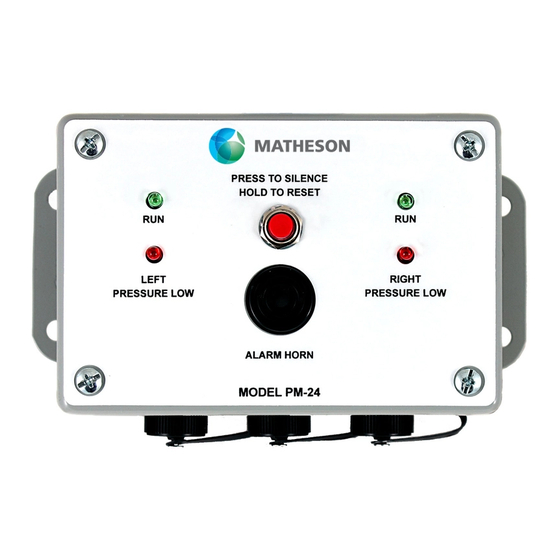
V. GENERAL DESCRIPTION The MATHESON Pressure Monitor, Model PM-24, was designed as a method of ensuring uninterrupted gas supplies, when used in conjunction with MATHESON switchover manifold systems. The unit consists of two components: An annunciator with audio/visual alarm The 120 VAC, 60HZ power adapter with 15VDC output Amphenol back shells, contact pins and connectors are also supplied to connect dry contact switch wires to the Left and Right input connectors. -
Page 10: Installation
(also supplied with the unit). Connect the left IPS to the left side connector on the PM-24, marked INP- L and the right side IPS to the connector marked INP-R on the bottom of the unit. -
Page 11: Operating Instructions
The PM-24 lights will reset from red to green only when the pressure is above the set point of the IPS and the red pushbutton, (Hold to Reset), is held in for three (3) seconds. -
Page 12: Trouble Shooting
Unit lights up, but there is Defective circuit or Return to MATHESON for no audible alarm with red alarm buzzer. repair. lights. Cylinder is above set Needs reset... - Page 13 Lights change from green Needs reset. Press and hold reset button to red when cylinder is for at least three (3) empty but will not reset seconds. when cylinder is replaced. Partial cylinder - Replace with higher replacement cylinder pressure cylinder (full pressure is not high cylinder).
-
Page 14: Drawings
IX. DRAWINGS... - Page 16 Copyright 2019 Matheson Tri-Gas, Inc. All Rights Reserved. All contents of this document are subject to change without notice and do not represent a commitment on the part of Matheson Tri- Gas, Inc. Every effort is made to ensure the accuracy of this information. However, due to differences in actual and ongoing operational processes and product improvements and revisions, Matheson Tri-Gas, Inc.
Need help?
Do you have a question about the PM-24 and is the answer not in the manual?
Questions and answers