Advertisement
Quick Links
Sketches / Skizzen
IP00
Footprints [mm] / Befestigungsmaße [mm]
120
MI.90.N1.5B - VLT® is a registered Danfoss trademark
IP20
125
135
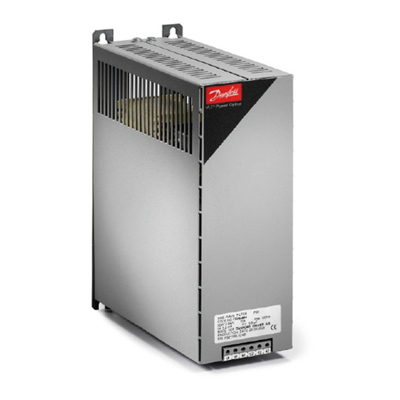
Sine-wave Filter MCC 101 -Technical data /Technische Daten
Nom.
Motor
Min.Sw.
Protect.
Code
current
Power
Freq.
degree
number
(50/60/100
(400V)
Hz)
Motor-
Min.
Schutz-
Bestell-
Nenn-
leistung
takt-
art
nummer
strom
(400V)
freq.
(50/60/100
Hz)
[A]
[kW]
IP00
130B2412
24/23/18
11
4
IP20
130B2447
IP00
130B2413
38/36/26,5
15-18.5
4
IP20
130B2448
IP00
130B2281
48/45,5/36
22
4
IP20
130B2307
IP00
130B2282
62/59/46,5
30
3
IP20
130B2308
IP00
130B2283
75/71/56
37
3
IP20
130B2309
Note: Tmax. 45˚C (UL) and Tmax 50˚C (CE)
Anmerkung: Tmax. 45˚C (UL) und Tmax 50˚C (CE)
Necessary drive adjustments / Notwendige Umrichtereinstellungen
– The VLT switching frequency must be set to the value specified for the individual filter.
Please consult the VLT Programming Guide for the corresponding parameter values.
– With an output filter installed only a reduced Automatic Motor Adaption (AMA) can be used.
– The filters are designed for a max. frequency of 100 Hz. For frequencies above 50 Hz the
nominal current may have to be reduced (see filter nameplate).
– Die Schaltfrequenz des VLT muss auf den für den jeweiligen Filter angegebenen Wert
eingestellt werden. Siehe Beschreibung im Programmierhandbuch.
– Mit einem installierten Ausgangsfilter kann nur eine reduzierte Automatische
Motoranpassung (AMA) durchgeführt werden.
– Die Filter sind auf eine max. Frequenz von 100 Hz ausgelegt. Bei Betrieb über 50 Hz muß
der Filter Nennstrom entsprechend reduziert werden (siehe Filter Typenschild).
Warnings / Warnung
– When in use the filter surface temperature rises. DO NOT touch the filter during operation.
– Never work on a filter in operation. Touching the electrical parts may be fatal – even after the
equipment has been disconnected from the drive or motor.
– Before servicing the filter, wait at least the voltage discharge time stated in the Design Guide
for the corresponding VLT® to avoid electrical shock hazard
– Never attempt to repair a defective filter
– Während des Betriebs steigt die Oberflächentemperatur des Filter, also berühren Sie NICHT
den Filter während des Betriebs
– Arbeiten Sie niemals an einem Filter, der gerade in Betrieb ist. Das Berühren elektrischer
Teile - auch nach der Trennung des Gerätes vom Netz - kann lebensgefährlich sein.
– Warten Sie mindestens die im Projektierungshandbuch angegebene Entladezeit für den
entsprechenden VLT® ab, bevor Sie Wartungsarbeiten am Filter durchführen, um das Risiko
eines Stromschlags zu vermeiden.
– Versuchen Sie niemals, einen beschädigten Filter zu reparieren.
MI.90.N1.5B - VLT® is a registered Danfoss trademark
Dimensions
Maße
A
a
B
b
C
c
d
e
f
330
312
150
120
260
12
19
9
9
157
430
412
150
120
260
12
19
9
9
157
530
500
170
125
258
12
19
9
9
177
610
580
170
125
260
12
19
9
9
177
610
580
170
135
260
12
19
9
9
177
Max. wire
cross
section
Max.
Anschl.
Quersch.
[mm
2
]
20
20
50
50
50
Advertisement

Summary of Contents for Danfoss MCC 101
- Page 1 Sketches / Skizzen Sine-wave Filter MCC 101 -Technical data /Technische Daten Nom. Motor Min.Sw. Protect. Code Dimensions Max. wire IP00 IP20 current Power Freq. degree number cross (50/60/100 (400V) section Motor- Min. Schutz- Bestell- Maße Max. Nenn- leistung takt- nummer Anschl.
- Page 2 MI.90.N1.5B - VLT® is a registered Danfoss trademark MCC 101 - Sine Wave Filter Installation guidelines Screening / Schirmung It is recommended to use screened cables to reduce the radiation of electromagnetic noise into the Installationsanweisungen environment and prevent malfunctions in the installation.


Need help?
Do you have a question about the MCC 101 and is the answer not in the manual?
Questions and answers