
Related Manuals for dallmeier Domera DJB-115W

Summary of Contents for dallmeier Domera DJB-115W
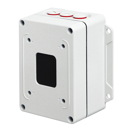
- Page 1 Installation English Outdoor Mounting Accessories Junction Box DJB-115W Rev. 2.0.0 / 003845 / 2012-03-15...
- Page 2 Third-party trademarks are named for information purposes only. Dallmeier electronic respects the intellectual property of third parties and always attempts to ensure the complete identification of third- party trademarks and indication of the respective holder of rights. In case that protected rights are not indicated separately, this circum- stance is no reason to assume that the respective trademark is unprotected.
-
Page 3: Table Of Contents
RS485 Interface ....................24 External Connections ..................25 6.3.1 UTP Terminal / LAN PoE Terminal ..............25 6.3.2 Video ......................25 6.3.3 Alarm IN / Relay OUT ...................26 6.3.4 RS485 Interface ....................26 6.3.5 Audio IN / Audio OUT ..................26 Technical Data and Drawings ..............27 www.dallmeier.com... -
Page 4: Introduction
In addition, safety instructions, general notes and technical data/drawings are provided. The target audience is trained and authorized professionals (installers). For detailed descriptions of the installation, connection, commissioning and configuration of the corresponding cameras, read the separate documentations referring to the prod- ucts. www.dallmeier.com... -
Page 5: Typographical Conventions
Expressions in bold/italics generally indicate a control element on the device (switches or labels) or on its user interface (buttons, menu entries). Paragraphs in italics provide information on basic principles, special features and efficient procedure as well as general recommendations. www.dallmeier.com... -
Page 6: Safety Instructions
System Components Only use internal components that have been tested and approved by Dallmeier. Inappropriate internal components can cause malfunctions, damages and data loss and can result in the loss of warranty. - Page 7 The housing of the unit may only be opened by qualified personnel for commissioning, inspection, maintenance and repair. Disposal Do not dispose waste electrical and electronic equipment into the household trash. Disconnect the unit from the power supply. Remove all connected devices. Return the unit to your respective sales partner. www.dallmeier.com...
-
Page 8: General Notes
Transportation and Packaging Store the original packaging for transportation at a later date. Dallmeier is not responsible for any damage resulting from unprofessional/improper trans- portation. The goods should only be shipped in their original packaging. -
Page 9: Performance Features Djb-115W
ADC KRONE LSA punch-down (insertion) tool or something similar • Compatible with all analogue and all IP (SD/HD) network PTZ dome cameras of the series • Housing with IP 66 ingress protection • Specially designed cable feed-throughs for IP 68 cable glands www.dallmeier.com... -
Page 10: Requirements
Outdoor use For the outdoor installation of PTZ dome cameras, always use the corre- sponding weather-proof housing. However, note that direct insolation can cause very high temperatures inside the housing. In this case use the corresponding sunshield. www.dallmeier.com... -
Page 11: Maintenance
Do not rub acrylic glass with a dry cloth. Do not use common glass cleaners. Avoid excessive rubbing. Dry gently with a clean dry cloth to avoid scratching the surface. www.dallmeier.com... -
Page 12: Installation
• Toggle bolt style anchors for drywall/hollow wall type (plaster) Wall Mount Bracket Outdoor 5.1.1 In-Wall Wiring 4× Universal dowel 10×50 4× Flat washer 8.4 DIN 125 A, A2 G 1 1/4" DIN ISO 228 4× Hexagon head wood screw 8×80 DIN 571, A2 Fig. 5-1 www.dallmeier.com... -
Page 13: On-Wall Wiring
Fig. 5-2 5.1.3 Pole Mounting Pole diameter 76 – 230 mm 4× Lock washer DIN 127 B, A2-70 Strap length 720 mm 4× Hexagon nut M10 DIN 934, A2-70 Pole mount bracket G 1 1/4" DIN ISO 228 Fig. 5-3 www.dallmeier.com... -
Page 14: Corner Mounting
8× Flat washer 8.4 DIN 125 A, A2 8× Universal dowel 10×50 Corner mount bracket 4× Hexagon nut M10 DIN 934, A2-70 8× Hexagon head wood screw 8×80 DIN 571 G 1 1/4" DIN ISO 228 4× Lock washer DIN 127 B, A2-70 Fig. 5-4 www.dallmeier.com... -
Page 15: Ceiling Mount Bracket
Outdoor Mounting Accessories – Junction Box DJB-115W Ceiling Mount Bracket 5.2.1 In-Wall Wiring 4× Universal dowel 10×50 4× Flat washer 8.4 DIN 125 A, A2 4× Hexagon head wood screw 8×80 DIN 571, A2 G 1 1/4" DIN ISO 228 Fig. 5-5 www.dallmeier.com... -
Page 16: On-Wall Wiring
DIN 127 B, A2-70 4× Flat washer Mounting plate 8.4 DIN 125 A, A2 4× Hexagon head wood screw 8×80 DIN 571, A2 4× Hexagon head screw M10×30, A2-70 ISO 4017 G 1 1/4" DIN ISO 228 Fig. 5-6 www.dallmeier.com... -
Page 17: Junction Box Djb-115W
Outdoor Mounting Accessories – Junction Box DJB-115W Junction Box DJB-115W 5.3.1 Wall Mounting 4× Universal dowel 10×50 4× Flat washer 8.4 DIN 125 A, A2 4× Hexagon head wood screw 8×80 DIN 571, A2 Fig. 5-7 www.dallmeier.com... -
Page 18: Pole Mounting
Fig. 5-8 Mounting plate to pole mount bracket Mounting plate for junction box 4× Hexagon nut M10 DIN 934, A2-70 4× Lock washer DIN 127 B, A2-70 4× Hexagon head screw M10×30, A2-70 ISO 4017 Fig. 5-9 Junction box to mounting plate www.dallmeier.com... -
Page 19: Corner Mounting
Fig. 5-10 Mounting plate to corner mount bracket Mounting plate for junction box 4× Hexagon nut M10 DIN 934, A2-70 4× Lock washer DIN 127 B, A2-70 4× Hexagon head screw M10×30, A2-70 ISO 4017 Fig. 5-11 Junction box to mounting plate www.dallmeier.com... -
Page 20: Wall Mount Bracket Outdoor To Front Panel
Outdoor Mounting Accessories – Junction Box DJB-115W 5.3.4 Wall Mount Bracket Outdoor to Front Panel Gasket Front panel 4× Hexagon head screw M10×14, A2-70 ISO 4017 G 1 1/4" DIN ISO 228 Weather-proof housing with sunshield Fig. 5-12 www.dallmeier.com... -
Page 21: Front Panel To Junction Box
IN R PoE−1 IN L IN GND TX− G 1 1/4" DIN ISO 228 Front panel 3× Cable gland M25 (IP 68) Fig. 5-13 4× Torx (T21) G 1 1/4" DIN ISO 228 Front panel Hinge joint Fig. 5-14 www.dallmeier.com... -
Page 22: Connections
“L” (live wire) and the AC neutral wire (return conductor) to the AC input terminal labelled with “N” (neutral wire). Finally, connect the camera and/or other equipment (e.g. heater of weather-proof hous- ing) to the AC output terminal. www.dallmeier.com... -
Page 23: Camera Connections
Fig. 6-3: UTP port / LAN PoE port (RJ45 female connector) Assignment Pin No. LAN Poe Video (+) Video (−) TX− RS485 (+) Power (GND) PoE−1 Power (+) PoE−2 RS485 (−) RX− Power (GND) PoE+1 Power (+) PoE+2 Table 6-1: Pin assignment UTP port / LAN PoE port www.dallmeier.com... -
Page 24: Alarm In / Relay Out
RELAY OUT (NO1) RELAY OUT (NO2) Fig. 6-4: Alarm IN / Relay OUT plug-in connectors 6.2.3 RS485 Interface RS485 RX + RX + RX − RX − TX + TX + TX − TX − Fig. 6-5: RS485 plug-in connector www.dallmeier.com... -
Page 25: External Connections
Power (+) / PoE−2 Power (GND) / PoE−1 RS485 (+) / RX+ Video (−) / TX− Video (+) / TX+ Fig. 6-7: LSA terminal block for UTP signal / LAN PoE 6.3.2 Video Fig. 6-8: Screw terminal block for video signal www.dallmeier.com... -
Page 26: Alarm In / Relay Out
AUDIO OUT LEFT CHANNEL OUT L AUDIO OUT GROUND OUT GND AUDIO IN RIGHT CHANNEL IN R AUDIO IN LEFT CHANNEL IN L AUDIO IN GROUND IN GND Fig. 6-11: LSA terminal block for Audio IN / Audio OUT www.dallmeier.com... -
Page 27: Technical Data And Drawings
Outdoor Mounting Accessories – Junction Box DJB-115W Technical Data and Drawings Following technical data and drawings were valid at the time of document compilation. Visit www.dallmeier.com for possible updates. Junction Box DJB-115W Camera Connections Video 1× BNC Audio IN 1× 3.5 mm phone jack Audio OUT 1×... - Page 28 Suitable Installation Site Indoor/Outdoor Operating Temperature −30 °C to +50 °C (-22 ºF to 122 ºF) Relative Humidity 0% – 90% RH, non-condensing IP Rating IP 66 Approvals/Certifications Type CE, DIN EN 50130-4 compliant Dimensions 145 mm (5.71") 214.5 mm (8.44") www.dallmeier.com...
- Page 29 Outdoor Mounting Accessories – Junction Box DJB-115W Dimensions 3× M25 194 mm (7.64") 90 mm (3.54") www.dallmeier.com...
- Page 30 Outdoor Mounting Accessories – Junction Box DJB-115W For Your Notes www.dallmeier.com...
- Page 31 Outdoor Mounting Accessories – Junction Box DJB-115W For Your Notes www.dallmeier.com...
- Page 32 Dallmeier electronic GmbH & Co.KG Cranachweg 1 93051 Regensburg Germany Tel.: +49 (0) 941 87 00-0 Fax: +49 (0) 941 87 00-180 www.dallmeier.com...
Need help?
Do you have a question about the Domera DJB-115W and is the answer not in the manual?
Questions and answers