Table of Contents
Advertisement
SPX Bolting Systems
Unit 4, Wansbeck Business Park
Rotary Parkway
Ashington
Northumberland NE63 8QW
Original Instructions
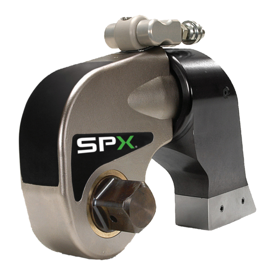
Square Drive Hydraulic Torque
© SPX
Tel: +44 (0) 1670 850580
Fax: +44 (0) 1670 850655
info@spxboltingsystems.com
Wrench
Operating Manual for:
TWSD Series
Form No. 1000528
Rev. 1 December 2, 2011
Advertisement
Table of Contents


Need help?
Do you have a question about the TWSD Series and is the answer not in the manual?
Questions and answers