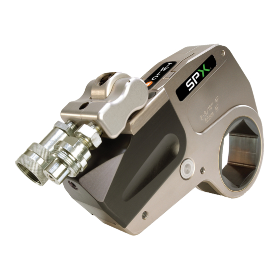
SPX TWLC Series Operating Manual

SPX TWLC Series Operating Manual

Low clearance hydraulic torque wrench

Advertisement

SPX Bolting Systems
Unit 4, Wansbeck Business Park
Rotary Parkway
Ashington
Northumberland NE63 8QW
Original Instructions
Low Clearance Hydraulic Torque
© SPX
Tel: +44 (0) 1670 850580
Fax: +44 (0) 1670 850655
info@spxboltingsystems.com
Wrench
Operating Manual for:
TWLC Series
Form No. 1000529
Rev. 1 December 6, 2011

Advertisement

Table of Contents
loading
Need help?

Need help?

Do you have a question about the TWLC Series and is the answer not in the manual?

Questions and answers

Summary of Contents for SPX TWLC Series

  • Page 1 SPX Bolting Systems Operating Manual for: TWLC Series Unit 4, Wansbeck Business Park Tel: +44 (0) 1670 850580 Rotary Parkway Fax: +44 (0) 1670 850655 Ashington info@spxboltingsystems.com Northumberland NE63 8QW Original Instructions Low Clearance Hydraulic Torque Wrench Form No. 1000529 ©...
  • Page 2: Table Of Contents

    TWL8 Torque Wrench: Head Parts List ..................43 TWL15 Torque Wrench: Head Parts List ..................47 TWL30 Torque Wrench: Head Parts List ..................52 EC Declaration of Conformity ......................... 58 Form No. 1000529 © SPX Rev. 1 December 6, 2011...
  • Page 3: Torque Wrench Low Clearance (Twlc)

    TWLC torque wrench is proportional to the pump pressure applied. MULTISWIVEL MANIFOLD QUICK-CHANGE HEAD HYDRAULIC COUPLINGS BODY REACTION PAD HEAD-RELEASE PIN Figure 1. TWLC Hydraulic Torque Wrench Form No. 1000529 © SPX Rev. 1 December 6, 2011...
  • Page 4: Safety Symbols And Definitions

    • Retract the system before adding fluid to prevent overfilling the pump reservoir. An overfill can cause personal injury due to excess reservoir pressure created when cylinders are retracted. Form No. 1000529 © SPX Rev. 1 December 6, 2011...
  • Page 5: Electric Motor

    Never attempt to grasp a leaking hose under pressure with your hands. The force of escaping hydraulic fluid could cause serious injury. Form No. 1000529 © SPX Rev. 1 December 6, 2011...
  • Page 6 Hoses also must not come in contact with corrosive material such as creosote- impregnated objects and some paints. Consult the manufacturer before painting a hose. Never paint the couplers. Hose deterioration due to corrosive materials may result in personal injury. Form No. 1000529 © SPX Rev. 1 December 6, 2011...
  • Page 7: Initial Setup

    Parker 3000 couplings. SPX Bolting Systems will not be responsible for torque wrench damage, malfunction or operator injury caused by the use of an incorrect pump unit; therefore, check the compatibility of your pump unit before operating the hydraulic torque wrench.
  • Page 8: Torque Wrench Usage

    Threaded connections such as fittings, gauges, etc., must be securely tightened and leak-free. Accessory Operation Links and reducers are available for each drive body. For more information, contact your SPX Bolting Systems authorized service center. Form No. 1000529 © SPX...
  • Page 9: Safety

    Never use the hydraulic torque wrench with just one hose connected to the Advance port (Port A). This will cause the pressure to intensify within the retract chamber possibly leading to tool damage. Always verify that both hoses are correctly connected. Form No. 1000529 © SPX Rev. 1 December 6, 2011...
  • Page 10: Preparing The Torque Wrench For Use

    Slide the drive head fully onto the body and push the head retaining pin back into position. Form No. 1000529 © SPX Rev. 1 December 6, 2011...
  • Page 11: Setting Torque

    If an intensification occurs, the valve will bleed hydraulic oil externally from the manifold yoke. Oil bleeding from the swivel manifold is not a sign of seal leakage. Form No. 1000529 © SPX Rev. 1 December 6, 2011...
  • Page 12 Before applying another advance stroke, make sure the pump is idling at 103 bar (1,500 psi), which indicates full retraction. Form No. 1000529 © SPX Rev. 1 December 6, 2011...
  • Page 13: Operating Instructions

    Flat surfaces are preferred. • Packing pieces, spacers, etc. must never be used as a makeshift reaction point. Reaction accessories are available to increase the access to reaction points. Form No. 1000529 © SPX Rev. 1 December 6, 2011...
  • Page 14: Use Of Backing Wrenches

    The torquing procedure uses a single hydraulic torque wrench to accurately achieve a predetermined residual bolt stress. Form No. 1000529 © SPX Rev. 1 December 6, 2011...
  • Page 15: Loosening Bolts

    (if the nut/bolt material will accept the higher torques without damage). Do not, under any circumstances, strike the hydraulic torque wrench or nut/bolt in an attempt to 'shock' the nut free. Form No. 1000529 © SPX Rev. 1 December 6, 2011...
  • Page 16 Do not, under any circumstances, strike the hydraulic torque wrench or nut/bolt in an attempt to 'shock' the nut free. Retract the hydraulic torque wrench, stop the pump unit, and remove the wrench from the nut. Form No. 1000529 © SPX Rev. 1 December 6, 2011...
  • Page 17: Performance Specifications

    65–120 (2 9/16–4 5/8) 1,782 14,850 19.0 (41.9) TWL30 80–155 (3 1/8–6 1/8) 3,456 28,800 38.0 (83.8) ** Note that minimum torque can be lower depending upon pump low-pressure capability Form No. 1000529 © SPX Rev. 1 December 6, 2011...
  • Page 18: Pressure/Torque Conversion Chart

    Pressure/Torque Conversion Chart Form No. 1000529 © SPX Rev. 1 December 6, 2011...
  • Page 19: General Maintenance

    Clean and inspect each hydraulic hose and quick-connect coupling. Check the entire length of the hose for cuts, abrasions, and damage. Replace the entire hose if any evidence of damage is present. Coat each quick-connect coupling with a water repellent spray. Form No. 1000529 © SPX Rev. 1 December 6, 2011...
  • Page 20: Maintenance, Service, And Warranty

    In accordance with our End of Life Policy, should the product be no longer required for use, it should be returned to TTS Ltd where it shall be disposed of in a safe and environmentally friendly manner. Form No. 1000529 © SPX Rev. 1 December 6, 2011...
  • Page 21: Troubleshooting

    Replace ratchet and drive Wrench incorrectly shoe. retracted. Allow time to fully retract. Weak/snapped drive shoe spring. Replace springs. Difficulty in hose connection. Pressure within hose. Vent hose. Damaged coupling. Replace coupling. Form No. 1000529 © SPX Rev. 1 December 6, 2011...
  • Page 22: Repair Procedures

    Inspect all components for damage and/ or excessive wear. Inspect the ratchet and drive shoe teeth for damage, cracks, etc. Any substandard component must be replaced immediately using genuine parts supplied by SPX Bolting Systems. Figure 7. Left-Hand Sideplate Form No. 1000529 ©...
  • Page 23: Torque Wrench Head Assembly

    Manually rotate the ratchet verifying free movement and correct ratcheting action. Following stripdown and/or lubrication, the hydraulic torque wrench should be calibrated to verify that the torque output is within specified limits. Form No. 1000529 © SPX Rev. 1 December 6, 2011...
  • Page 24: Multiswivel Manifold Disassembly

    A (advance) and R (retract) to indicate the correct position of the as- sociated yoke. Reversal of the yokes will cause the torque wrench to malfunction and can lead to damage. Form No. 1000529 © SPX Rev. 1 December 6, 2011...
  • Page 25: Hydraulic Cylinder/Body Disassembly

    Attach open ended couplings to the multiswivel Gland manifold. Body Pull the shuttle forward sufficiently to gain Figure 11. Gland Location access to the gland. Be prepared to catch oil spillage vented from the retract coupling. Form No. 1000529 © SPX Rev. 1 December 6, 2011...
  • Page 26 Screw Verify that the spring-loaded shuttle pins move Piston seal freely, and check the condition of the shuttle Figure 14. Piston Disassembled pin ends for damage. Form No. 1000529 © SPX Rev. 1 December 6, 2011...
  • Page 27: Hydraulic Cylinder/Body Assembly

    Apply full pressure to the torque wrench (690 bar/10,000 psi advance; 103 bar/1,500 psi retract), and check for leaks. Form No. 1000529 © SPX Rev. 1 December 6, 2011...
  • Page 28: Parts Lists

    Parts Lists TWLC2/4 Torque Wrench Parts List Part No. Item No. Description TWLC2 TWLC4 LDFAS020002 LDFAS040002 TWLC body assembly STDFA000070 STDFA000070 –Plug LDFBD020001 LDFBD040001 –TWLC body Form No. 1000529 © SPX Rev. 1 December 6, 2011...
  • Page 29 TWLC piston rod DFTPI020001 DFTPI040001 TWLC piston STDFA000024 STDFA000033 Screw — LDFTP040001 TWLC top plate LDFLA020001 LDFLA040001 TWLC decal — STDFA000029 Screw — STDST000079 *TWLC body has integral top plate. Form No. 1000529 © SPX Rev. 1 December 6, 2011...
  • Page 30 Parts Lists continued (TWLC2) (TWLC4) 11.2 11.1 11.3 Form No. 1000529 © SPX Rev. 1 December 6, 2011...
  • Page 31: Twlc2 Torque Wrench: Head Parts List

    STDFA000088 Screw DFTSL020001 TWL2 slider STDST000012 Spring DFTDS020002 TWL2 drive shoe (head 2) — TWL2 ratchet (head 2) — DFTRT020002E — 1 5/8 in./41 mm A/F (head 2) STDFA000042 Screw Form No. 1000529 © SPX Rev. 1 December 6, 2011...
  • Page 32 DFTAS020020 TWL2 left sideplate (head 4) assembly DFTSJ020004 -TWL2 sideplate bush (head 4) DFTLA020004 -TWL2 decal STDST000073 -Dome plug STDFA000062 Screw DFTLS020001 TWL2 leaf spring STDFA000088 Screw DFTSL020001 TWL2 slider Form No. 1000529 © SPX Rev. 1 December 6, 2011...
  • Page 33 TWL2 crank (head 5) **Replace as a pair. Head Ref: TWL2-6 Item No. Part No. Description DFTHP020001 TWL2 head pin DFTAS020026 TWL2 left sideplate (head 6) assembly DFTLA020004 -TWL2 decal Form No. 1000529 © SPX Rev. 1 December 6, 2011...
  • Page 34: Twl4 Torque Wrench: Head Parts List

    1 5/8 in./41 mm A/F (head 1) STDFA000045 Screw STDFA000043 Screw DFTAS040008 TWL4 right sideplate (head 1) assembly 11.1 DFTSJ040001 -TWL4 sideplate bush (head 1) 11.2 STDST000074 -Dome plug 11.3 DFTLA040004 -TWL4 decal Form No. 1000529 © SPX Rev. 1 December 6, 2011...
  • Page 35 DFTSJ040003 -TWL4 sideplate bush (head 3) STDFA000062 Screw DFTLS040001 TWL4 leaf spring STDFA000088 Screw DFTSL040001 TWL4 slider STDST000013 Spring DFTDS040003 TWL4 drive shoe (head 3) — TWL4 ratchet (head 3) Form No. 1000529 © SPX Rev. 1 December 6, 2011...
  • Page 36 Head Ref: TWL4-5 Item No. Part No. Description DFTHP040001 TWL4 head pin DFTAS040019 TWL4 left sideplate (head 5) assembly DFTLA040004 -TWL4 decal STDST000074 -Dome plug DFTSJ040005 -TWL4 sideplate bush (head 5) Form No. 1000529 © SPX Rev. 1 December 6, 2011...
  • Page 37 TWL4 right sideplate (head 6) assembly 11.1 DFTSJ040006 -TWL4 sideplate bush (head 6) STDST000074 11.2 -Dome plug 11.3 DFTLA040004 -TWL4 decal DFTCR040006 TWL4 crank (head 6) **Replace as a pair. Form No. 1000529 © SPX Rev. 1 December 6, 2011...
  • Page 38 TWL4 drive shoe (head 8) — TWL4 ratchet (head 8) — DFTRT040008C — 2 15/16 in./75 mm A/F (head 8) STDFA000045 Screw STDFA000043 Screw DFTAS040029 TWL4 right sideplate (head 8) assembly Form No. 1000529 © SPX Rev. 1 December 6, 2011...
  • Page 39 TWL4 right sideplate (head 9) assembly 11.1 DFTSJ040009 -TWL4 sideplate bush (head 9) 11.2 STDST000074 -Dome plug 11.3 DFTLA040004 -TWL4 decal DFTCR040009 TWL4 crank (head 9) **Replace as a pair. Form No. 1000529 © SPX Rev. 1 December 6, 2011...
  • Page 40 Parts Lists continued Form No. 1000529 © SPX Rev. 1 December 6, 2011...
  • Page 41: Twl8/15/30 Torque Wrench Parts List

    Seal Body Seal Kit Body Seal Kit Body Seal Kit DFTAS080005 DFTAS150005 DFTAS300005 Seal Seal DFTRD080001 DFTRD150001 DFTRD300001 TWLC piston rod DFTPI080001 DFTPI150001 DFTPI300001 TWLC piston STDFA000036 STDFA000037 STDFA000037 Screw Form No. 1000529 © SPX Rev. 1 December 6, 2011...
  • Page 42 Parts Lists continued Part No. item Description TWLC8 TWLC15 TWLC30 LDFTP080001 LDFTP150001 LDFTP300001 TWLC top plate LDFLA080001 LDFLA150001 LDFLA300001 TWLC decal STDFA000032 STDFA000034 STDFA000035 Screw STDST000080 STDST000081 STDST000081 Form No. 1000529 © SPX Rev. 1 December 6, 2011...
  • Page 43 Parts Lists continued Form No. 1000529 © SPX Rev. 1 December 6, 2011...
  • Page 44: Twl8 Torque Wrench: Head Parts List

    TWL8 left sideplate (head 2) assembly DFTLA080004 -TWL8 decal STDST000075 -Dome plug DFTSJ080002 -TWL8 sideplate bush (head 2) STDFA000063 Screw DFTLS080001 TWL8 leaf spring STDFA000021 Screw DFTSL080001 TWL8 slider STDST000014 Spring Form No. 1000529 © SPX Rev. 1 December 6, 2011...
  • Page 45 14.1 DFTSJ080003 -TWL8 sideplate bush (head 3) 14.2 DFTLA080004 -TWL8 decal 14.3 STDST000075 -Dome plug LDFFS080003 TWL8 front spacer (head 3) DFTCR080003 TWL8 crank (head 3) **Replace as a pair. Form No. 1000529 © SPX Rev. 1 December 6, 2011...
  • Page 46 TWL8 leaf spring STDFA000021 Screw DFTSL080001 TWL8 slider STDST000014 Spring DFTDS080005 TWL8 drive shoe (head 5) — TWL8 ratchet (head 5) DFTRT080005B — — 3 1/8 in./80 mm A/F (head 5) Form No. 1000529 © SPX Rev. 1 December 6, 2011...
  • Page 47 14.1 DFTSJ080006 -TWL8 sideplate bush (head 6) 14.2 DFTLA080004 -TWL8 decal 14.3 STDST000075 -Dome plug LDFFS080006 TWL8 front spacer (head 6) DFTCR080006 TWL8 crank (head 6) **Replace as a pair. Form No. 1000529 © SPX Rev. 1 December 6, 2011...
  • Page 48: Twl15 Torque Wrench: Head Parts List

    DFTAS150007 TWL15 left sideplate (head 1) assembly DFTLA150004 -TWL15 decal STDST000076 -Dome plug DFTSJ150001 -TWL15 sideplate bush (head 1) STDFA000065 Screw DFTLS150001 TWL15 leaf spring STDFA000022 Screw DFTSL150001 TWL15 slider Form No. 1000529 © SPX Rev. 1 December 6, 2011...
  • Page 49 14.1 DFTSJ150002 -TWL15 sideplate bush (head 2) 14.2 DFTLA150004 -TWL15 decal 14.3 STDST000076 -Dome plug LDFFS150002 TWL15 front spacer (head 2) DFTCR150002 TWL15 crank (head 2) **Replace as a pair. Form No. 1000529 © SPX Rev. 1 December 6, 2011...
  • Page 50 DFTSJ150004 -TWL15 sideplate bush (head 4) STDFA000065 Screw DFTLS150001 TWL15 leaf spring STDFA000022 Screw DFTSL150001 TWL15 slider STDST000015 Spring — TWL15 ratchet (head 4) DFTDS150004 TWL15 drive shoe (head 4) Form No. 1000529 © SPX Rev. 1 December 6, 2011...
  • Page 51 14.1 DFTSJ150005 -TWL15 sideplate bush (head 5) 14.2 DFTLA150004 -TWL15 decal 14.3 STDST000076 -Dome plug LDFFS150005 TWL15 front spacer (head 5) DFTCR150005 TWL15 crank (head 5) **Replace as a pair. Form No. 1000529 © SPX Rev. 1 December 6, 2011...
  • Page 52 DFTSJ150007 TWL15 sideplate bush (head 7) STDFA000065 Screw DFTLS150001 TWL15 leaf spring STDFA000022 Screw DFTSL150001 TWL15 slider STDST000015 Spring DFTDS150007 TWL15 drive shoe (head 7) — TWL15 ratchet (head 7) Form No. 1000529 © SPX Rev. 1 December 6, 2011...
  • Page 53: Twl30 Torque Wrench: Head Parts List

    LDFRS300001 TWL30 rear spacer (head 1) STDFA000092 Screw STDFA000090 Screw STDFA000093 Screw DFTAS300008 TWL30 right sideplate (head 1) assembly 14.1 DFTSJ300001 -TWL30 sideplate bush (head 1) 14.2 DFTLA300004 -TWL30 decal Form No. 1000529 © SPX Rev. 1 December 6, 2011...
  • Page 54 Item No. Part No. Description DFTHP300001 TWL30 head pin DFTAS300013 TWL30 left sideplate (head 3) assembly DFTLA300004 -TWL30 decal STDST000077 -Dome plug DFTSJ300003 -TWL30 sideplate bush (head 3) STDFA000065 Screw Form No. 1000529 © SPX Rev. 1 December 6, 2011...
  • Page 55 TWL30 ratchet (head 4) DFTRT300004A — 115 mm A/F (head 4) — DFTRT300004B — 4 5/8 in. A/F (head 4) LDFRS300004 TWL30 rear spacer (head 4) STDFA000092 Screw STDFA000090 Screw STDFA000093 Screw Form No. 1000529 © SPX Rev. 1 December 6, 2011...
  • Page 56 TWL30 crank (head 5) **Replace as a pair. Head Ref: TWL30-6 Item No. Part No. Description DFTHP300001 TWL30 head pin DFTAS300022 TWL30 left sideplate (head 6) assembly DFTLA300004 -TWL30 decal Form No. 1000529 © SPX Rev. 1 December 6, 2011...
  • Page 57 TWL30 drive shoe (head 7) — TWL30 ratchet (head 7) — DFTRT300007B — 5 3/4 in./145 mm A/F (head 7) LDFRS300007 TWL30 rear spacer (head 7) STDFA000092 Screw STDFA000090 Screw Form No. 1000529 © SPX Rev. 1 December 6, 2011...
  • Page 58 14.1 DFTSJ300008 -TWL30 sideplate bush (head 8) 14.2 DFTLA300004 -TWL30 decal 14.3 STDST000077 -Dome plug LDFFS300008 TWL30 front spacer (head 8) DFTCR300008 TWL30 crank (head 8) **Replace as a pair. Form No. 1000529 © SPX Rev. 1 December 6, 2011...
  • Page 59: Ec Declaration Of Conformity

    SPX Bolting Systems is the person authorised to compile the technical file. SPX Bolting Systems, the manufacturer / supplier, undertake to transmit and / or make available in response to reasoned request, technical file details and other relative information to EEC National...

This manual is also suitable for:

Twlc2Twlc8Twlc4Twlc30Twlc15

Table of Contents

Save PDF