Table of Contents
Advertisement
Quick Links
WIRELESS REMOTE/STRAP-ON
TEMPERATURE SENSORS
Installation & Operation Instructions
SST5630
GENERAL INFORMATION
The SST5630 is a battery operated spread spectrum
wireless remote/strap-on temperature sensor. It is
designed for monitoring refrigeration or freezers
from -300°F (-184°C) to 300°F (149°C).
The RTD sensor is encapsulated in a 0.187" O.D. 304
stainless steel probe (2" probe length) for single
point pipe temperature monitoring.
ACI's wireless sensors utilize reliable Spread
Spectrum Radio technology. They can be installed
easily in minutes eliminating hundreds of feet of
wire and saving installation cost while reducing
installation labor risks.
The sensor Data-Link LED con rms the data
transmission was received by the receiver for fast
and reliable positioning of the sensor during
installation. There is no need for special wireless installation equipment or tool.
Together with the ACI receivers and controllers, the ACI wireless sensors can be used with any LON works,
BACnet, Modbus, system or panel.
The maximum radio transmission distance is dependent on the building type. In a typical commercial
building with steel I-Beam construction, concrete oors with reinforcing rod, and metal stud walls, it can be
expected that transmissions will penetrate vertically typically one oor below and one oor above a
transceiver/receiver, and horizontally through 200 to 300 feet of walls, furniture and air.
MOUNTING INSTRUCTIONS
Wireless sensors should be installed within 200 to 300 feet of the receiver. RR2552 signal repeaters can be
installed as to increase transmission distance between sensors and receivers.
CAUTION:
Observe battery polarity when installing battery.
To select the proper sensor location, rst install and power the receiver. To activate the sensor insert the
battery observing the polarity.
While the sensor is attempting to connect to the receiver the Data-Link LED will blink rapidly 8–10 times
every 10 seconds. Once a connection has been established the Data-Link LED will blink once to indicate
Automation Components, Inc.
2305 Pleasant View Road | Middleton, WI 53562
Phone: 1-888-967-5224 | Website: workaci.com
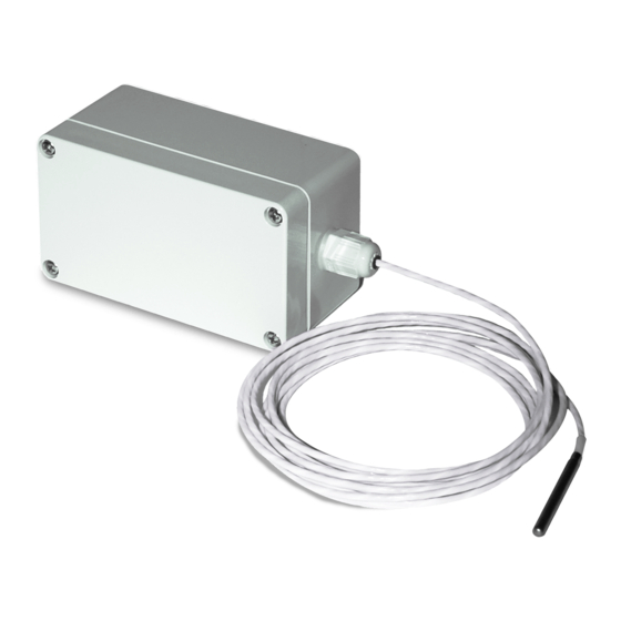
FIGURE 1: ENCLOSURE DIMENSIONS
Battery Positive
Terminal
SST5630AE
Altech Water
Tight Fitting
Internal Link
Button
NEMA 4X Enclosure
10' Cable
2.00" x 0.187" Probe
Page 1
Phone: 1-888-967-5224
Website: workaci.com
4.53"
2.56"
2.23"
Version: 6.0
I0000701
Advertisement
Table of Contents

Subscribe to Our Youtube Channel
Related Manuals for aci SST5630


Summary of Contents for aci SST5630
- Page 1 There is no need for special wireless installation equipment or tool. Together with the ACI receivers and controllers, the ACI wireless sensors can be used with any LON works, BACnet, Modbus, system or panel.
- Page 2 FIGURE 2: ENCLOSURE MOUNTING WIRE INSTALLATION ACI recommends installing the wire through the door seal, probe access port, or cooler wall. On horizontal units, the preferred method is using the rear door seal as shown in Figure 3. On vertical units, remove the rear panel.
- Page 3 - see FIGURE 5 (p.2). Drill a 1/4” screw through the socket and tighten to the wall. If a thermal bu er is required, use a glycol kit (ACI Item #130127). Drill pilot holes for the provided mounting screws. Use the mounting clip holes as a guide - see FIGURE 6 (p.2).
- Page 4 Flammability Rating: WARRANTY The ACI Wireless Series are covered by ACI’s Two (2) Year Limited Warranty, which is located in the front of ACI’S SENSORS & TRANSMIT TERS CATALOG or can be found on ACI’s website: www.workaci.com. W.E.E.E. DIRECTIVE At the end of their useful life the packaging and product should be disposed of via a suitable recycling centre.
Need help?
Do you have a question about the SST5630 and is the answer not in the manual?
Questions and answers