
Subscribe to Our Youtube Channel
Related Manuals for Halma Crowcon Xgard

Summary of Contents for Halma Crowcon Xgard
- Page 1 Xgard Gas Detectors Installation, operating and maintenance instructions M07249 Issue 8 October 2007...
- Page 2 Safety information • Xgard gas detectors must be installed, operated and maintained in strict accordance with these instructions, warnings, label information, and within the limitations stated. • The lid on flameproof versions of Xgard must be kept tightly closed until power to the detector is isolated otherwise ignition of a flammable atmosphere can occur.
- Page 3 Safety information Hazardous area classifications: Zone 0: An area classified as Zone 0 will have ignitable concentrations of flammable gases, vapours or liquids either continuously present or present for long periods of time under normal operating conditions. Intrinsically Safe (Exia) detectors are suitable for use in Zone 0, provided they are connected via a suitable zener barrier or galvanic isolator.
- Page 4 DAMP CLOTH is present Xgard ATEX and IECEx Xgard ATEX and IECEx Intrinsically Safe Flameproof CROWCON XGARD GAS DETECTOR TYPE 1 CROWCON XGARD GAS DETECTOR TYPE OXYGEN -40°C < Ta < +55°C T4 Exia 40ºF T +122ºF T6 40ºF T +176ºF T4...
-
Page 5: Type 5 Flameproof Flammable Gas Detector With 4 20Ma Output41
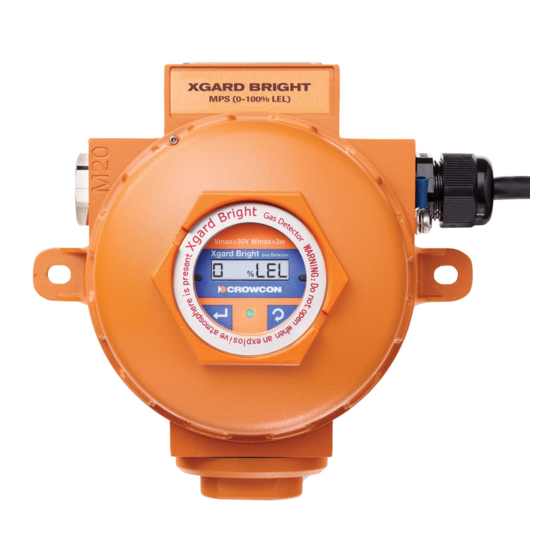
Overview Each type of Xgard detector is identified by a label fitted on the junction box body. Please quote the ‘model number’, ‘gas range’ and ‘sensor type’ when contacting Crowcon for advice or spares. This manual covers all versions of Xgard, care should be taken to ensure that the correct section is referenced according to the type of detector used. - Page 6 Overview 36 Slot Slots to suit M6 or 1/4” fixings for ceiling mount 146 CRS 166.3 Overall Height 111 All dimensions in millimetres Diagram 2: Xgard dimensioned view...
- Page 7 Overview Grub screw Certification label PCB cover (M04770) Enclosure base Lid O ring (M04829) Amplifier PCB Sensor module Sensor seal Sensor retainer O ring (M04828) Sensor retainer Grub screw Diagram 3: Xgard exploded view (part numbers shown in brackets where applicable. For part numbers not shown, see Spares and Accessories on page 59)
-
Page 8: Table Of Contents
Table of contents Type 1 Intrinsically safe toxic and oxygen gas detector ..9 1. Introduction ..................9 2. Installation ..................10 3. Operation..................13 4. Specification...................16 Type 2 Flameproof toxic and oxygen gas detector ...17 1. -
Page 9: Type 1 Intrinsically Safe Toxic And Oxygen Gas Detector
1. Introduction Xgard Type 1 1.1 Intrinsically safe toxic and oxygen gas detector This version of Xgard is an Intrinsically safe loop powered (current sink) 4 20 mA toxic or oxygen gas detector, designed to detect a wide range of gases when fitted with the appropriate electrochemical sensor. The detector is certified II 1 G EEx ia IIC T4, and is suitable for use in Zone 0, Zone 1 and Zone 2 hazardous areas when used with a suitable... -
Page 10: Installation
2. Installation Xgard Type 1 WARNING This detector is designed for use in Zone 0, Zone 1 and Zone 2 hazardous areas, and is certified II 1 G EEx ia IIC T4 when used with a suitable Zener barrier or galvanic isolator. Installation must be in accordance with the recognised standards of the appropriate authority in the country concerned. - Page 11 2. Installation Xgard Type 1 2.2 Mounting Xgard should be installed at the designated location with the sensor pointing down. This ensures that dust or water will not collect on the sensor and stop gas entering the cell. The mounting detail is shown in Diagram 2.
- Page 12 2. Installation Xgard Type 1 2.4 Electrical connections All connections are made via the screw terminal block mounted on the amplifier PCB in the junction box. The terminals are marked ‘+’ and ‘ ’ and correct polarity should be observed when connecting the detector to control equipment.
-
Page 13: Operation
3. Operation Xgard Type 1 WARNING Prior to carrying out any work ensure local regulations and site procedures are followed. Never attempt to open the detector or junction box when flammable gas is present. Ensure that the associated control panel is inhibited so as to prevent false alarms. - Page 14 3. Operation Xgard Type 1 x 150 + 40 = 136 mV 9. If the control equipment display requires adjustment consult the operating manual for the equipment. 10.Remove the gas and allow the sensor to completely settle before re checking the zero setting. 11.Close the junction box of the detector ensuring that the lid is securely tightened, and the grub screw is secured.
- Page 15 3. Operation Xgard Type 1 When performing maintenance on Xgard, ensure that the sensor retainer and junction box lid O rings are present and in good condition to maintain the ingress protection of the product. See the ‘Spare parts and accessories’...
-
Page 16: Specification
4. Specification Xgard Type 1 Junction box material ATEX: Glass filled nylon UL Version: Aluminium 316 Stainless Steel (optional) Dimensions 156 x 166 x 111 mm (6.1 x 6.5 x 4.3 inches) Weight Alumnium: 1 kg (2.2 lbs) Glass filled Nylon: 0.5 kg (1.1lb) Stainless Steel: 3.1 kg (6.8lbs) approx. -
Page 17: Type 2 Flameproof Toxic And Oxygen Gas Detector
1. Introduction Xgard Type 2 1.1 Flameproof toxic and oxygen gas detector This version of Xgard is a Flameproof loop powered (current sink) 4 20 mA toxic or oxygen gas detector, designed to detect a wide range of gases when fitted with the appropriate electrochemical sensor. The detector is certified II 2 GD EExd IIC T6, and is suitable for use in Zone 1 and Zone 2 hazardous areas. -
Page 18: Installation
2. Installation Xgard Type 2 WARNING This detector is designed for use in Zone 1 and Zone 2 hazardous areas, and is certified II 2 GD EExd IIC T6. Installation must be in accordance with the recognised standards of the appropriate authority in the country concerned. - Page 19 2. Installation Xgard Type 2 2.2 Mounting Xgard should be installed at the designated location with the sensor pointing down. This ensures that dust or water will not collect on the sensor and stop gas entering the cell. The mounting detail is shown in Diagram 2.
- Page 20 2. Installation Xgard Type 2 2.4 Electrical connections All connections are made via the screw terminal block mounted on the amplifier PCB in the junction box. The terminals are marked ‘+’ and ‘ ’ and correct polarity should be observed when connecting the detector to control equipment.
-
Page 21: Operation
3. Operation Xgard Type 2 WARNING Prior to carrying out any work ensure local regulations and site procedures are followed. Never attempt to open the detector or junction box when flammable gas is present. Ensure that the associated control panel is inhibited so as to prevent false alarms. - Page 22 3. Operation Xgard Type 2 9. If the control equipment display requires adjustment consult the operating manual for the equipment. 10.Remove the gas and allow the sensor to completely settle before re checking the zero setting. 11.Close the junction box of the detector ensuring that the lid is securely tightened, and the grub screw is secured.
- Page 23 3. Operation Xgard Type 2 When performing maintenance on Xgard, ensure that the sensor retainer and junction box lid O rings are present and in good condition to maintain the ingress protection of the product. See the ‘Spare parts and accessories’...
-
Page 24: Specification
4. Specification Xgard Type 2 Junction box material A356 marine grade alloy with polyester powder coating 316 Stainless Steel (optional) Dimensions 156 x 166 x 111 mm (6.1 x 6.5 x 4.3 inches) Weight Alloy: 1 kg (2.2 lbs) Stainless Steel: 3.1 kg (6.8lbs) approx. Operating voltage 8–30 V dc Output... -
Page 25: Type 3 Flameproof Flammable Gas Detector
1. Introduction Xgard Type 3 1.1 Flameproof flammable gas detector This version of Xgard is a Flameproof gas detector, designed to detect flammable gas present in ambient air, at concentrations not exceeding the Lower Explosive Limit (LEL) of the target gas for which it is calibrated. Xgard Type 3 operates using pellistors as part of a 3 wire Wheatstone Bridge (WB) circuit, and must be connected to a suitable control card. -
Page 26: Installation
2. Installation Xgard Type 3 WARNING This detector is designed for use in Zone 1 and Zone 2 hazardous areas, and is certified II 2 GD EExd IIC T6 for operation up to 50°C (122°F), II 2 GD EExd IIC T4 for operation up to 80°C (176°F). - Page 27 2. Installation Xgard Type 3 2.2 Mounting Xgard should be installed at the designated location with the sensor pointing down. This ensures that dust or water will not collect on the sensor and stop gas entering the cell. The mounting detail is shown in Diagram 2.
- Page 28 2. Installation Xgard Type 3 The following cable lengths are calculated assuming a 300mA constant current drive, with a minimum supply of 18 V dc from the control equipment: C.S.A. Resistance Max. Distance Max. Distance (Ohms per km) (km) (km) Cable Loop 2.0 volt pellistors 2.5 volt pellistors...
-
Page 29: Operation
3. Operation Xgard Type 3 WARNING Prior to carrying out any work ensure local regulations and site procedures are followed. Never attempt to open the detector or junction box when flammable gas is present. Ensure that the associated control panel is inhibited so as to prevent false alarms. - Page 30 3. Operation Xgard Type 3 3.2 Routine maintenance Pellistors can suffer from loss of sensitivity when there is a presence of poisons or inhibitors such as silicones, sulphides, chlorine, lead or halogenated hydrocarbons. Crowcon use poison resistant pellistors to maximise the operational life of Xgard. In applications where such compounds are continuously present we recommend the use of Crowcon’s fixed point infrared flammable gas detectors, which are immune to such poisons and inhibitors.
- Page 31 3. Operation Xgard Type 3 3.3 Sensor replacement/servicing of detectors Xgard uses a modular design, which makes replacement of sensors, or sinters extremely simple. Replacement sensors are supplied fitted to a sensor PCB to allow simple plug in installation. An exploded view of Xgard is given in Diagram 3.
-
Page 32: Specification
4. Specification Xgard Type 3 Junction box material A356 marine grade alloy with polyester powder coating 316 Stainless Steel (optional) Dimensions 156 x 166 x 111 mm (6.1 x 6.5 x 4.3 inches) Weight Alloy: 1 kg (2.2 lbs) Stainless Steel: 3.1 kg (6.8lbs) approx. Electrical output 3 wire mV bridge. -
Page 33: Introduction
1. Introduction Xgard Type 4 1.1 Flameproof high temperature flammable gas detector This version of Xgard is a Flameproof high temperature (150°C / 302°F) gas detector, designed to detect flammable gas present in ambient air, at concentrations not exceeding the Lower Explosive Limit (LEL) of the target gas for which it is calibrated. -
Page 34: Installation
2. Installation Xgard Type 4 WARNING This detector is designed for use in Zone 1 and Zone 2 hazardous areas, and is certified II 2 G EExd IIC T3. Installation must be in accordance with the recognised standards of the appropriate authority in the country concerned. - Page 35 2. Installation Xgard Type 4 2.2 Mounting Xgard should be installed at the designated location with the sensor pointing down. This ensures that dust or water will not collect on the sensor and stop gas entering the cell. The mounting detail is shown in Diagram 2.
- Page 36 2. Installation Xgard Type 4 The following cable lengths are calculated assuming a 300mA constant current drive, with a minimum supply of 18 V dc from the control equipment: C.S.A. Resistance Max. Distance Max. Distance (Ohms per km) (km) (km) Cable Loop 2.0 volt pellistors 2.5 volt pellistors...
-
Page 37: Operation
3. Operation Xgard Type 4 WARNING Prior to carrying out any work ensure local regulations and site procedures are followed. Never attempt to open the detector or junction box when flammable gas is present. Ensure that the associated control panel is inhibited so as to prevent false alarms. - Page 38 3. Operation Xgard Type 4 3.2 Routine maintenance Pellistors can suffer from loss of sensitivity when there is a presence of poisons or inhibitors such as silicones, sulphides, chlorine, lead or halogenated hydrocarbons. Crowcon use poison resistant pellistors to maximise the operational life of Xgard. In applications where such compounds are continuously present we recommend the use of Crowcon’s fixed point infrared flammable gas detectors, which are immune to such poisons and inhibitors.
- Page 39 3. Operation Xgard Type 4 3.3 Sensor replacement/servicing of detectors Xgard uses a modular design, which makes replacement of sensors extremely simple. Xgard Type 4 uses a high temperature detector, which must be replaced as a whole, complete with sensor retainer (see page 33).
-
Page 40: Specification
4. Specification Xgard Type 4 Junction box material A356 marine grade alloy with polyester powder coating 316 Stainless Steel (optional) Dimensions 195 x 166 x 111 mm (7.6 x 6.5 x 4.3 inches) Weight Alloy: 1.5 kg (3.3 lbs) Stainless Steel: 3.6 kg (7.9lbs). Electrical output 3 wire mV bridge. -
Page 41: Introduction
1. Introduction Xgard Type 5 1.1 Flameproof flammable gas detector This version of Xgard is a Flameproof gas detector, designed to detect flammable gas present in ambient air, at concentrations not exceeding the Lower Explosive Limit (LEL) of the target gas for which it is calibrated. Xgard Type 5 is powered by 24 V dc (nominally) and provides a 4 20 mA signal (sink or source) proportional to the gas concentration. -
Page 42: Installation
2. Installation Xgard Type 5 WARNING This detector is designed for use in Zone 1 and Zone 2 hazardous areas, and is certified II 2 GD EExd IIC T6. Installation must be in accordance with the recognised standards of the appropriate authority in the country concerned. - Page 43 2. Installation Xgard Type 5 2.2 Mounting Xgard should be installed at the designated location with the sensor pointing down. This ensures that dust or water will not collect on the sensor and stop gas entering the cell. The mounting detail is shown in Diagram 2.
- Page 44 2. Installation Xgard Type 5 2.4 Electrical connections All connections are made via the screw terminal block mounted on the PCB in the junction box. The terminals are marked ‘+’, ‘sig’ and ‘ ’ and correct polarity should be observed when connecting the detector to control equipment.
-
Page 45: Operation
3. Operation Xgard Type 5 WARNING Prior to carrying out any work ensure local regulations and site procedures are followed. Never attempt to open the detector or junction box when flammable gas is present. Ensure that the associated control panel is inhibited so as to prevent false alarms. - Page 46 3. Operation Xgard Type 5 x Gas + 40 = mV setting Range Example: calibrating using 25% LEL test gas x 25 + 40 = 80 mV 10. If the control equipment display requires adjustment consult the operating manual for the equipment. 11.
- Page 47 3. Operation Xgard Type 5 3.2 Routine maintenance Pellistors can suffer from loss of sensitivity when there is a presence of poisons or inhibitors such as silicones, sulphides, chlorine, lead or halogenated hydrocarbons. Crowcon use poison resistant pellistors to maximise the operational life of Xgard. In applications where such compounds are continuously present we recommend the use of Crowcon’s fixed point infrared flammable gas detectors, which are immune to such poisons and inhibitors.
- Page 48 3. Operation Xgard Type 5 3.3 Sensor replacement/servicing of detectors Xgard uses a modular design, which makes replacement of sensors, or sinters extremely simple. Replacement sensors are supplied fitted to a sensor PCB to allow simple plug in installation. An exploded view of Xgard is given in Diagram 3.
-
Page 49: Specification
4. Specification Xgard Type 5 Junction box material A356 marine grade alloy with polyester powder coating 316 Stainless Steel (optional) Dimensions 156 x 166 x 111 mm (6.1 x 6.5 x 4.3 inches) Weight Alloy: 1 kg (2.2 lbs) Stainless Steel: 3.1 kg (6.8lbs) approx. Operating voltage 10 30 V dc Current consumption... -
Page 50: Type 6 Flameproof Thermal Conductivity Type Gas Detector
1. Introduction Xgard Type 6 1.1 Flameproof thermal conductivity type gas detector This version of Xgard is a Flameproof thermal conductivity type gas detector, designed to monitor binary gas mixtures (such as hydrogen in nitrogen, methane in carbon dioxide) in % volume concentrations. The detector relies on there being a substantial difference in the thermal conductivity properties of the gases in the mixture being monitored. -
Page 51: Installation
2. Installation Xgard Type 6 WARNING This detector is designed for use in Zone 1 and Zone 2 hazardous areas, and is certified II 2 GD EExd IIC T6. Installation must be in accordance with the recognised standards of the appropriate authority in the country concerned. - Page 52 2. Installation Xgard Type 6 2.2 Mounting Xgard should be installed at the designated location with the sensor pointing down. This ensures that dust or water will not collect on the sensor and stop gas entering the cell. The mounting detail is shown in Diagram 2.
- Page 53 2. Installation Xgard Type 6 2.4 Electrical connections All connections are made via the screw terminal block mounted on the PCB in the junction box. The terminals are marked ‘+’, ‘sig’ and ‘ ’ and correct polarity should be observed when connecting the detector to control equipment.
-
Page 54: Operation
3. Operation Xgard Type 6 WARNING Prior to carrying out any work ensure local regulations and site procedures are followed. Never attempt to open the detector or junction box when flammable gas is present. Ensure that the associated control panel is inhibited so as to prevent false alarms. - Page 55 3. Operation Xgard Type 6 control equipment display reads zero. Calibrating the detector 8. Apply calibration gas (which should either be 100% volume target gas, or be a representative mix of the required range, for example 60% CH 4 / 40% CO 2 ) to the detector at a flow rate of 0.5 1 litre/minute via a flow adaptor (Part No.
- Page 56 3. Operation Xgard Type 6 3.2 Routine maintenance The operational life of the sensor depends on the application for which it is being used. It is expected that a thermal conductivity sensor will work satisfactorily for up to 5 years in ideal conditions. Sensors are prone to damage by vibration and shock, so measures should be taken to ensure that the detector is not affected by these influences.
- Page 57 3. Operation Xgard Type 6 3.3 Sensor replacement/servicing of detectors Xgard uses a modular design, which makes replacement of sensors, or sinters extremely simple. Replacement sensors are supplied fitted to a sensor PCB to allow simple plug in installation. An exploded view of Xgard is given in Diagram 3.
-
Page 58: Specification
4. Specification Xgard Type 6 Junction box material A356 marine grade alloy with polyester powder coating 316 Stainless Steel (optional) Dimensions 156 x 166 x 111 mm (6.1 x 6.5 x 4.3 inches) Weight Alloy: 1 kg (2.2 lbs) Stainless Steel: 3.1 kg (6.8lbs) approx. Operating voltage 10 30 V dc Current consumption... -
Page 59: Spare Parts And Accessories
Spare parts and accessories Please refer to the Sensor Type section on the main junction box label for the correct replacement sensor part number. Description Part Xgard Number Version Sensor retainer (aluminium) M01840 Type 1 only (UL) Sensor retainer (Glass filled Nylon) M04774 Type 1 only (ATEX) Sensor retainer with sinter (aluminium) - Page 60 Spare parts and accessories Accessory adaptor Spray deflector C011061 C01052 Weatherproof cap Flow adaptor C01442 C01339 Collector cone Sun Shade C01051 C011063 Note: these accassories are not compatible with Xgard Type 4...
-
Page 61: Appendix: Sensor Limitations
Appendix: Sensor limitations The sensors used in Xgard have limitations common to all such gas sensors, and users should be aware of the points listed below. Crowcon can advise on particular situations and suggest alternative sensors if the instrument is likely to experience extreme conditions. •... -
Page 62: Warranty
Warranty This equipment leaves our factory fully tested and calibrated. If within the warranty period of one year from Despatch, the equipment is proved to be defective by reason of faulty workmanship or material, we undertake at our option either to repair or replace it free of charge, subject to the conditions below. - Page 63 Warranty implied statutory or otherwise as to the merchantable quality of our equipment or its fitness for any particular purpose is excluded except as prohibited by statute. This guarantee shall not affect a customer’s statutory rights. Crowcon reserves the right to apply a handling and carriage charge whereby units returned as faulty, are found to require only normal calibration or servicing, which the customer then declines to proceed with.
- Page 64 UK Office USA Office Crowcon Detection Instruments Ltd, Crowcon Detection Instruments Ltd, 2 Blacklands Way, 21 Kenton Lands Road Abingdon Business Park, Erlanger Abingdon, Kentucky 41018 1845 Oxfordshire OX14 1DY, UK Tel: +44 (0)1235 557700 Tel: +1 859 957 1039 or Fax: +44 (0)1235 557749 1 800 527 6926...
Need help?
Do you have a question about the Crowcon Xgard and is the answer not in the manual?
Questions and answers