Advertisement
Table of Contents
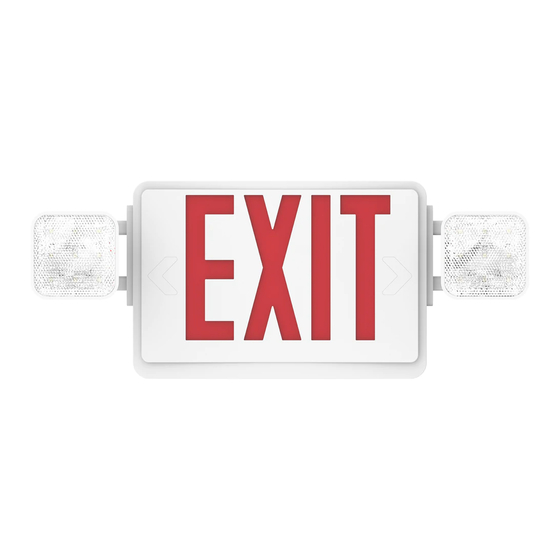
EXIT LED SIGN
Install Guide and Manual
CEILING MOUNT
1.
Turn Power OFF
3.
5.
7.
Battery
Battery
Connector
Socket
CEILING
MOUNT
DIAGRAM
Disconnect AC power, make sure the battery is
unplugged before servicing
•If you are replacing an existing halogen fixture,
allow the fixture to cool away from flammable
materials.
Unsnap canopy hole cover on the top of fixture
Connect leads to AC input leads in the Junction Box.
Black wire for 120V, Red/Orange wire for 277V
•Cap off unused wires
•Feed excess wire into a junction box
Connect the battery (see figure)
Junction
Box
Wire Nuts
Screws
Bracket
Canopy
Plastic
Housing
Diffuser
Snap-in
Directional Arrow
Exit Panel
2.
Unsnap faceplate to open (see figure)
•For dual-sided EXIT sign, remove backplate
and replace with extra faceplate (included)
4.
Feed lead wires through a hole on the top of the
fixture, ensure wires are secured into wire guides
Canopy
6.
Attach canopy to j-box using bracket and screws
(included), wires will go through the center hole in
the canopy
•Snap housing to canopy
Canopy
8.
Snap-in arrows on EXIT faceplate as required
9.
Secure faceplate to housing
10.
Test after 24 hours of charging
Button
IMPORTANT
The battery in this unit may not be fully charged. After electricity
is connected to the unit, let the battery charge for at least 24
hours before performing any tests. To test, process "TEST" button
and sign should illuminate. Only use LED specified for the fixture
when re-lamping.
EQUIPMENT: Flat head Philips screwdriver, drill recommended.
The Brighter Choice
Advertisement
Table of Contents

Related Manuals for Sunco EXIT LED SIGN

Summary of Contents for Sunco EXIT LED SIGN
- Page 1 The Brighter Choice EXIT LED SIGN Install Guide and Manual CEILING MOUNT Disconnect AC power, make sure the battery is Unsnap faceplate to open (see figure) unplugged before servicing •For dual-sided EXIT sign, remove backplate •If you are replacing an existing halogen fixture,...
- Page 2 The Brighter Choice Wire Nuts Plastic Housing Back Plate EXIT LED SIGN Install Guide and Manual Diffuser Snap-in Directional Arrow Exit Panel WALL MOUNT WALL MOUNT DIAGRAM Disconnect AC power, make sure the battery is Unsnap faceplate to open (see figure) unplugged before servicing •If you are replacing an existing halogen fixture,...
Need help?
Do you have a question about the EXIT LED SIGN and is the answer not in the manual?
Questions and answers