Table of Contents
Advertisement
Quick Links
Advertisement
Table of Contents

Related Manuals for Optocore DD32R-FX

Summary of Contents for Optocore DD32R-FX
- Page 1 AES/EBU I/O / SANE/ VIDEO / DATA MODULE WITH ETHERNET Optical Digital Network Device © Copyright 2020 All rights reserved OPTOCORE GmbH Alte Allee 28 81245 Munich Germany DD32R-FX – Digital I/O for Optocore and SANE Operating Manual Rev. 2.4...
- Page 2 Page intentionally left blank.
-
Page 3: Important Safety Instructions
Never switch on power amplifiers before the complete system is stable and the level meters of • the OPTOCORE CONTROL software indicate a normal level. Do not place this device on an unstable table, tripod, cart, etc. The device may fall, causing •... -
Page 4: Purchaser Information
Leave sufficient space (minimum ½ RU) between the device and any heat emitting devices housed in the same rack. A DD32R-FX may be placed on top or beneath other Optocore products, except a DD32E, without additional space. - Page 5 Never push objects of any kind into the device through openings in the casing. They may come into contact with dangerous voltage points or short out parts that could result in a fire or electric shock. Never spill liquid of any kind on the device. DD32R-FX 5 / 26 rev. 2.4...
- Page 6 Such operation can lead to damage of the device’s components due to lack of air-flow through the device. The device may not be serviced, altered or modified without authorization from Optocore or an Optocore authorized distributor / dealer. Only qualified service personnel may carry out repair and maintenance work on the device.
-
Page 7: Ce/Fcc-Conformity
Operation of this equipment in a residential area is likely to cause harmful interference, in which case you will be required to correct the interference at his own expense. Changes or modifications not expressly approved by Optocore GmbH could void the user’s authority to operate this equipment. - Page 8 Page intentionally left blank.
-
Page 9: Table Of Contents
DD32R-FX – AES/EBU I/O interface for Optocore and SANE Table of Contents Important Safety Instructions ............................. 3 Purchaser Information ............................... 4 CE/FCC-Conformity ..............................7 Device Description ..............................10 Front Panel ................................12 Rear Panel ................................14 Device Details ................................. 15 Optocore Fiber Optic Connection ........................ -
Page 10: Device Description
The DD32R-FX enables to connect to the SANE network via RJ45 ports. It is possible to use SANE as a Cat5 based cost-efficient extension to the optical core system. SANE ports may be used as point-to-point MADI over Cat5 or as a bridge interface between SANE and OPTOCORE, providing up to 128 input and 128 output channels additionally to the principal AES/EBU ports. - Page 11 The software can be operated offline as well as online with level meters for all channels on the network The LEDs on the front panel of the DD32R-FX units allow an instant overview regarding the status of each port. DD32R-FX 11 / 26 rev.
-
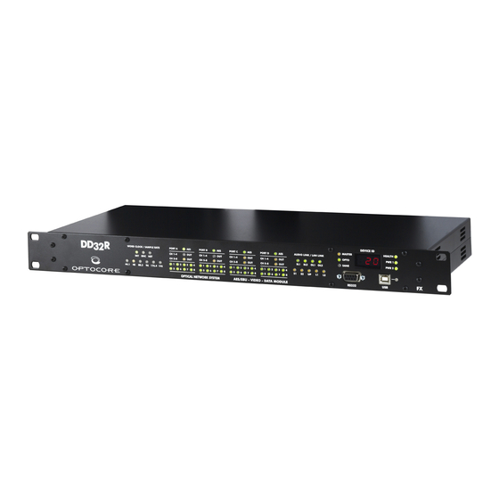
Page 12: Front Panel
SL1: Communication is established via SANE 1 (rear panel) SL2: Communication is established via SANE 2 (rear panel) OL1: Communication is established via Optocore LINK 1 (rear panel) OL2: Communication is established via Optocore LINK 2 (rear panel) Master LED:... - Page 13 Ethernet communication is established via LAN 1 (rear panel) Ethernet communication is established via LAN 2 (rear panel) Sample Rate LED: Yellow 44,1 / 48 / 88,2 / 96 / 176,4 / 192 kHz DD32R-FX 13 / 26 rev. 2.4...
-
Page 14: Rear Panel
RS485/GPIO plug: 4 x RS485/RS422 (D-Sub-9) auxiliary port for data transmission Word Clock IN: BNC Word clock input allowing synchronization of Optocore devices/network from an external word clock source Word Clock OUT: BNC Word clock output for synchronization of external devices... -
Page 15: Device Details
Optocore network depending on configuration. Ethernet Ports DD32R-FX supports Optocore and SANE Ethernet transport. Two LAN ports interface with all other LAN and SANE/LAN ports in the Optocore and SANE Network creating a large unmanaged virtual 100Mbit Ethernet switch. -
Page 16: Power Supply
The monitoring and operational facilities are only available if a DD32R-FX is connected directly to a PC via LAN, USB or RS232. In order to connect and control more than one unit tin the Optocore or SANE networks with a PC the Control is transmitted through the network. -
Page 17: Optocore Bandwidth Allocation
Optocore bandwidth allocation The standard bandwidth allocation of an Optocore network is as follows: 256 Channels @ 48 KHz – 1 Gbit network Audio 768 Channels @ 48 kHz – 2 Gbit network RS485 Data 32 Channels Video 3 CVBS Video Channels *... -
Page 18: Connectors And Cables
> 40 dB between 30 MHz up to 1 GHz. The shield of the cable should have contact to the connector hood. USB-Connection Use a USB-A to USB-B cable between the PC and the Optocore device. LAN-Connection Use standard twisted-pair-cable (Cat-5, Cat-6) with RJ-45 connector. -
Page 19: Hardware Connection
For word clock distribution, the Word Clock OUT of the DD32R-FX should be connected to the Word Clock IN of one X6R. Then using a daisy chain of BNC cables, the word clock is passed on to the other X6Rs in the system, from the Word Clock OUT to the Word Clock IN of the consecutive X6R, etc. -
Page 20: Example 2
Fig. 2: Connection of four X6R units and one DD32R In this example Ports A and B of the DD32R-FX are outputs, sending their signals to first two cards installed in console’s slot. Ports C and D are connected to the third card with 8 inputs and 8 outputs each. Each of these ports transmits four AES/EBU (8 audio channels) outputs and receives four AES/EBU inputs. -
Page 21: Connection Tables
SANE port for Ethernet data communication. 1, 4, 6 7, 8 D-Sub-9- female Locking system acc. to 4-40 UNC RJ-45 Pin-out USB-Port Channel VBUS USB device-connector Pin-out Optical Fibre-Port Optocore LC connectors DD32R-FX 21 / 26 rev. 2.4... - Page 22 Use standard RS232 cable, male – bridged +5VS female, to connect to PC 1, 4, 6 7, 8 D-Sub-9- female Locking system acc. to 4-40 UNC Pin-out USB-Port Channel VBUS USB device-connector X6R/V3R-FX 15 / 19 rev. 2.0 DD32R-FX 22 / 26 rev. 2.4...
-
Page 23: Technical Specifications
USB 2.0 - Device 12 Mbit/s TIA-568A/B, IEEE - 802.3 10/100 Mbit/s SANE, LAN Convention Audio TIA - 568A/B, Optocore 200 Mbit/s TIA - 568A/B, IEEE - 802.3 10/100 Mbit/s Optical Connection Complies with 21 CFR 1040.10 and 1040.11 Power supply... -
Page 24: Dimensions And Weight
200 mm / 7.87 inch Rear panel: width 438 mm / 17.25 inch Weight 2.7 kg ≡ 4.41 lbs Please note: Modifications that serve the purpose of technical improvement may be carried out without prior notification. DD32R-FX 24 / 26 rev. 2.4... -
Page 25: Warranty And Liability
The warranty will be void if you tamper with internal components. Please address any questions or inquiries to OPTOCORE or your distributor/dealer. For a full warranty conditions refer to the Warranty Card attached to every Optocore device with a first shipment. How to Obtain Warranty Service When discovering a problem with an OPTOCORE device, you should contact either Optocore directly or a dealer/distributor to determine and confirm a hardware fault. -
Page 26: Shipping Contents
Shipping Contents The standard shipment of a DD32R-FX unit contains the following: 1 DD32R-FX unit • 1 fibre patch cable LC-LC • 2 power cables • Any additionally purchased equipment such as optical wave-guide cables in required lengths, D-Sub cables and adapters, RS232 cables, and international electric cables, which have been supplied on your request and your purchase order, cannot be listed above.
Need help?
Do you have a question about the DD32R-FX and is the answer not in the manual?
Questions and answers