Table of Contents
Advertisement
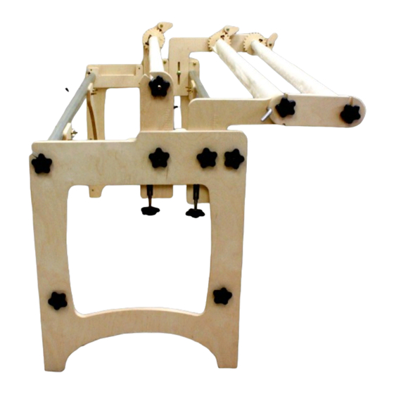
MACHINE QUILTING FRAME
YOU WILL NEED TO PURCHASE:
5 pieces of 1-1/4" thin wall metal conduit (EMT) cut to your preferred
length for the rollers. (Maximum 120")
DETERMINING YOUR ROLLER LENGTH:
Determine the width of the widest quilt you would like to make on the
frame. Add min. 8" to that width for your final roller length. The extra 8" allows
for extra room for your machine at the sides of the quilt. You also may want to
have an open space at the end of your frame to wheel your machine out from
under the quilt for maintenance.
If you would like to have 2 sets of rollers, we have a hardware package
available. Please call (319) 378-0999 or visit our website at
www.hinterberg.com.
OPTIONAL TEMPLATE SURFACE:
A 1/2" x 8" pine board, cut 1-½" longer than your roller length can be used
for a template board surface.
Pre-patterned grooved template boards are available from us at an addi-
tional cost. Board length fits 10' rollers. A 1/2" x 8" pine board is required to
support the grooved template board.
STAINING & FINISHING:
Applying a stain and finish to the frame is optional. It will not harm it to
leave it unfinished. If you wish to stain or finish your frame, it is easier to do
before you assemble it. What stain you use depends on your own prefer-
ence, but we recommend using a penetrating oil base wipe-on stain or a
combination stain/polyurethane for best results. Since there are moving
parts on your frame, we do not recommend any finish like varnish or shel-
lac that build up on the surface of the wood.
Please see our website
or email info@hinterberg.com with questions.
www.hinterberg.com
Revised 10/08
1
or call (319) 378-0999
Advertisement
Table of Contents

Subscribe to Our Youtube Channel
Related Manuals for Hinterberg Design Machine quilting frame

Summary of Contents for Hinterberg Design Machine quilting frame
- Page 1 MACHINE QUILTING FRAME YOU WILL NEED TO PURCHASE: 5 pieces of 1-1/4” thin wall metal conduit (EMT) cut to your preferred length for the rollers. (Maximum 120”) DETERMINING YOUR ROLLER LENGTH: Determine the width of the widest quilt you would like to make on the frame.
- Page 2 MACHINE QUILTING FRAME FRONT BACK...
- Page 3 HARDWARE Height Adjuster 3057 1/4” Machine Screw 3111 Roller End Insert 3028 1-1/4” Wood Screw 3047 1-1/2” Lag Screw 3031 Barrel Nut 3056 1-1/4” Lag Screw 3032 1/4” Wing Nut 3049 Hex Wrench 3053 1/4” Hex Head Bolt 3045 J-Hook 3018 3/8”...
- Page 4 MACHINE FRAME HARDWARE End Frame Hardware Carriage Handle Hardware DESCRIPTION PART# QTY. DESCRIPTION PART# QTY. Height Adjuster Assemblies Knobs with Short 5/8” studs 3112 1/4” x 1-1/4” Hex Head Screws 3056 Knob with Long 1 1/8” stud 3113 1/4” Metal Washers 3021 Machine Screws 1/4”...
- Page 5 WOOD PARTS...
- Page 6 MACHINE FRAME WOOD PARTS LIST Part # Qty. A Left End Frame 4031 B Right End Frame 4030 C Front left roller support guide 4025 D Front right roller support guide 4026 E Right template support 4028 F Left template support 4029 G Angle brace 1 4056...
- Page 7 END FRAME ASSEMBLY INSTRUCTIONS Locate bag of hardware labeled “End Frame Hardware” STEP 1. Assembling Front Roller Supports Use 1 1/4” Phillips head wood screws to attach the spacers to the front roller sup- ports, matching slots and pre drilled holes. RIGHT FRONT ROLLER RIGHT SPACER See Fig.
- Page 8 STEP 3. Template Support Locate the right end frame and the right tem- plate support. Both inside and outside edges of the end frames are rounded over. The template supports are only rounded over on one edge. The flat side goes against the end frame for a close fit.
- Page 9 STEP 6. Height Adjusters Lay the right side end frame on a flat sur- face. Locate the height adjuster assemblies. Lay two height adjuster bolts into the slots in the end frame. (The hole is slightly oval to allow for minor variations in wood.) Notice the hole in the barrel nut is off center.
- Page 10 Insert Lock Pin STEP 8. Here Attaching Roller Supports Insert a 2” carriage bolt through the hole in the slot in each roller support and through the corresponding hole in the end frame. The square base of the head of the bolt should sit down in the slot.
- Page 11 ROLLER END ASSEMBLY INSTRUCTIONS Locate bag of hardware labeled “Roller End Hardware” STEP 1. Inserting Metal Roller Ends Tap the inserts into the end of the metal rollers evenly with a hammer. Don’t tap on the end of the bolt, because you may damage the threads.
- Page 12 RATCHET WHEEL ASSEMBLY INSTRUCTIONS Locate bag of hardware labeled “Roller End Hardware” STEP 1. Assembling Ratchet Wheels WASHER The 3 ratchet wheels will be attached to the right end of 3 of the conduit rollers. Using the hardware found in the ‘roller end hardware’...
- Page 13 ATTACHING CARRIAGE TRACKS INSTRUCTIONS STEP 1. FRONT REAR Attaching the Carriage Tracks FRAME FRAME Before attaching the leg braces to the end frames, You will need to attach the end frames and the carriage tracks. To do this, stand both end frames up and insert the front car- riage track through the hole in each end frame.
- Page 14 LEG BRACE ASSEMBLY INSTRUCTIONS Locate bag of hardware labeled “Leg Brace Hardware” STEP 1. Angle Brace Assembly Locate the (4) angle braces. The angle braces anchor the carriage track to the end frames. This provides stability for the whole frame. The angle brace is designed to hold the roller support with the J-hook bolts.
- Page 15 ROLLER ASSEMBLY INSTRUCTIONS MIDDLE REAR STEP 1. Assembling the Rollers FRONT Set each of the end frames so that the front roller support is in the ‘up’ position. Set each of the 3 conduit rollers into the slots in the end frame. All of the ratchet wheels should be on the right hand side of the frame.
- Page 16 CENTER SUPPORT INSTRUCTIONS Locate bag of hardware labeled “Center Support Hardware” STEP 1. Lay the Center support up- right in the pocket in the Top support w/ round hole. See FRONT REAR FRONT REAR Fig. 1 Lay the Top support with the square hole on top of the other two parts as shown in Fig.
- Page 17 STEP 4. Insert allen head bolts through roller bracket. Scoop on top The scoop on the roller bracket is located towards the top of the center support. See Fig. 6. Use four barrel nuts and allen head screws to attach the roller brackets to each end of the top supports.
- Page 18 CARRIAGE HANDLE INSTRUCTIONS Locate bag of hardware labeled “Carriage Handle Hardware” STEP 1. Begin Handle Assembly FRONT Use machine screws to attach L-shaped handle part to bottom of upper slide. See Fig. 1. The slide has threaded inserts in the bottom. Insert the first screw part way, carefully en- BACK gaging the threaded insert.
- Page 19 POINTER PACKAGE INSTRUCTIONS Parts: Part # A Wood T-support 1201 B Wood gripper 1200 C Wood stylus holder 1202 D Black Bar Knob 3116 E Small black knob 3077 Laser Pointer 3078 G Metal stylus fastener 3079 H Metal U-shape 3080 STEP 1.
- Page 20 STEP 3. Attach Gripper to Carriage Insert the stud on the large knob through the gripper and into the threaded hole in the T- support. You can screw the knob into the hole a few turns and then slide it onto the end of the carriage. See Fig 4 One side of the gripper is larger than the other, make sure that you have the gripper oriented the...
- Page 21 TIPS FOR USING TEMPLATES • You can reverse your Machine Frame handles by removing the hand speed control and the knob at the top of the “T” part of the handles. Slide the crossbar out, reattach your handles on the rear of the frame, reattach your hand speed control and then you are comfortably seated at the rear of the frame.
- Page 22 END TENSIONERS Attach sticky back Velcro to end frames. Attach spring clamps to edge of quilt. Pull edges of quilt tight and secure to end frame using attached Velcro. Your quilt backing may be much wider than your quilt top. Attach end tensioners to edge of quilt back and use pins to secure edge of top to backing.
- Page 23 ADDING SEWING MACHINE INSTRUCTIONS STEP 1. Setting Carriage on Tracks This picture shows the correct orientation of the lower and upper slide on the car- riage tracks. See Fig. 25. The upper slide sits on the lower slide, which in turn sits on the carriage tracks.
- Page 24 (eg. 120” rollers – 2” + 118” leaders). The three leaders will be cut from this length of fabric. 2. For the Original Machine Quilting Frame, you will cut one length about 15” wide, one 10” wide and one 5” wide.
- Page 25 DIRECTIONS FOR ATTACHING LEADERS (APRONS) STEP 1 Standing at the front of your frame, or so that the end of the frame with the ratchet wheels is on your right side. Tape the long edge of the fabric to the rollers using any heavy-duty tape, such as duct tape or cloth mending tape.
- Page 26 LOADING YOUR QUILT ONTO THE FRAME These instructions are written as though you are standing in front of your frame, or so that the end of the frame with the ratchet wheels is on your right hand side. Take your time with this process, as it is critical for satisfactory results. Step 1.
- Page 27 Step 3. Gripping the middle roller with your hands, roll all but approximately 18” of the backing fabric onto the middle roller. It may help to have two people to roll this on large quilts. Make sure there are no wrinkles in the backing fabric as you roll, and make sure the fabric is not being stretched as you roll.
- Page 28 Step 5. Lay your quilt top carefully on top of your bat- ting. Spread it out evenly. (See Fig. 6) It helps if your quilt backing and batting are approx. 4” wider than your quilt top. This way, if your quilt top is not perfectly straight, you can easily trim away the extra batting and fabric after you are done quilting and the quilt is off the frame.
- Page 29 • Our website has more tips on how to use your Hinterberg frame. Please go to: www.hinterberg.com/ tips.aspx Machine Quilting Frame Disassembly 1. Unplug power source. 2. Remove the upper handle assembly from the machine carriage. 3. To remove the machine, loosen end knobs on the rear roller. Raise the left end (side without ratchet wheel) of the rear roller enough to guide the machine out from under the roller.
- Page 30 USING YOUR MACHINE FRAME Adjusting Roller Supports MIDDLE REAR We have provided height adjuster screws with FRONT black knobs in order to make adjusting your roller heights easier. You should adjust your rear roller so that your quilt just skims the base of your sewing machine. The front and middle roller assembly can be ad- justed as well to keep your quilt surface flat.
Need help?
Do you have a question about the Machine quilting frame and is the answer not in the manual?
Questions and answers
I have a tin lizzie on this frame and needing pointer package. Do you have them? Also on on the poles tighten up on both directions, can you help with that?