
Related Manuals for Absolute Ozone ATLAS Series


Summary of Contents for Absolute Ozone ATLAS Series
- Page 1 ABSOLUTE OZONE OZONE GENERATOR Models ATLAS/TITAN/MAGNUM 25-200 OPERATOR’S MANUAL Absolute Ozone 10712 - 181 Street, Edmonton, Alberta, T5S 1K8, Canada 780-486-3761...
-
Page 2: Table Of Contents
TABLE OF CONTENTS SECTION 1 – General Information ..............2 1A. Description ....................3 1B. Specifications (Ozone Output) ..............3 1C. Layout & Accessories ................. 3 1C.1 Ozone Generation................3 1C.2 Required Accessories ................4 SECTION 2 - Installation ..................5 2A. Location ....................5 2B. -
Page 3: Section 1 - General Information
6G.3 Eye Contact ..................18 6G.4 Precautions ..................17 6G.5 Emergency Information Form ............. 18 Absolute Ozone Five Years Limited Warranty ..........19 7 Ozone Generator Dimensions and Mounting Dimensions… ......20 8 Typical Ozone Injection System Diagram …………… ......…..21 SECTION 1 –... -
Page 4: Description
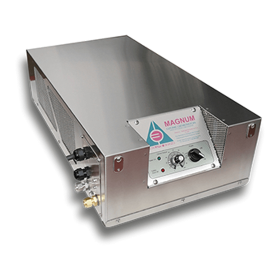
1A. Description The ATLAS/TITAN/MAGNUM 25-200 are Ozone Generators that produce from 1 to 160 grams of ozone per hour respectively, with ozone concentration up to 14% by weight or as specified in attached test report. The ATLAS/TITAN/MAGNUM 25-200 are designed to produce ozone for variety of applications such as: •... -
Page 5: Required Accessories
In our experience, Oxygen Concentrators made by AirSep work well with all Absolute Ozone generators. • To protect Absolute Ozone Generator from sieve particles in case of oxygen concentrator failure we recommend installing Oxygen Filter Upstream from the generator. -
Page 6: Section 2 - Installation
SECTION 2 - Installation 2A. Location The ATLAS/TITAN/MAGNUM 25-200 Ozone Generators are designed to be installed on the wall, on the rack or stack up system in convenient location mobile cart or skied. Allow for access to protected electrical power and required gas connections and cooling air to the Ozone Generator. -
Page 7: Electrical
2B. Electrical Main Power Supply Circuit: The ATLAS/TITAN/MAGNUM 25-200 are supplied with 3-5 feet power cord. Connect the power cord to a standard grounded 15 Amp (10 Amp International) power source, according to a local electrical code only. 2C. Plumbing When injecting Ozone in to water all measures should be taking to protect the Generator Cell from water exposure, which may cause internal cell damage. -
Page 8: Remote Control
2E. Remote Control All Absolute Ozone Generators are equipped with standard “On/Off” remote control terminals to enabling operator, ambient ozone monitor or PLC to remotely switch the Ozone Generator On or Off. This contacts have to be connected to dry contact only (not connected to the... - Page 9 Full (Optional) 4-20mA Remote Control Description and Schematic Full remote control features: • Remote control of ozone production level by 4-20mA or 0-10 VDC signal, no special switching for both of these signals required • Remote On/Off. Remote Switch must be normally open for the generator to be “On”...
-
Page 10: Section 3 - Operation
Full Remote Control Connection Schematic 4-20mA /0-10VDC Input BLACK Connection W HITE Remote On/Off GREEN ORANGE Remote Status BLUE Indicator Dry Relay Contacts BROW N 1A, 120-240VAC/24VDC Use Shielded Cable Only! Ground Shield Only on One Side! To switch from manual control operation to remote control please switch jumper in the middle PCB from pins 1-2 to 2-3 Remote Control Cables of required length are... -
Page 11: System Startup
3B. System Startup 5. Make sure the Ozone Generator enclosure is securely attached to an appropriate frame or wall Ozone Generators Stack. 6. Make sure all connections to the generator, power and gas are made according to local codes and regulations. 7. -
Page 12: Section 4 - Maintenance And Service
• Make sure to maintain working pressure across ozone cell as specified for the generator protection and most efficient ozone production. • When injecting ozone in to water make sure to protect the generator from flooding by installing device capable of preventing water backup. Check valves usually start leaking after few days of operation in ozone and cause serious damage to the ozone cell. - Page 13 any problem persists, please call 780-486-3761. We will have one of our system engineers discuss your situation with you over the phone. Symptom: Green, Red or Amber indicator lights “OFF”, POWER Switch is in the “ON” position and the cooling fan is not running. Check if the power coming to the generator.
-
Page 14: Section 5 - Replacement Parts
Absolute Ozone facilities only. On a rare occasion (must be authorized by Absolute Ozone technicians only), if any of the parts have to be replaced in the field Absolute Ozone will provide those parts to the customer. Please contact our service department. -
Page 15: Ozone Uses
• Highly chemically reactive • Non-flammable, non-carcinogenic • Hazardous polymerization can occur in some rear materials • Spontaneously decomposes to oxygen gas 6B.2 Ozone Uses • Air and water disinfection • Surface sanitation • Water treatment plants • Bottled water, irrigation, community water supplies, swimming pools/spas, etc. -
Page 16: Electrical Hazards
6C.3 Electrical Hazards Turn OFF all power switches and disconnect power cord from power source receptacle before performing service work. Failure to do so could result in serious injury or death. Operate the ATLAS/TITAN/MAGNUM 25-200 with safe access to electrical power. Connect the ATLAS/TITAN/MAGNUM 25-200 to a G.F.C.I. -
Page 17: Ozone Monitors
6D.1 Ozone Monitors Ambient ozone monitoring equipment should be installed in the areas where ozone is being generated or applied. (See Monitoring section 6F.) Self-adhesive ozone monitor badges, such as the Chromair® System by K&M Environmental (Virginia Beach, VA, www.kandmenvironmental.com), may be used for personal or area monitoring for exposure times ranging from 5 minutes to 10 hours. -
Page 18: System Operation And Maintenance
A certificate of completion of such training shall be provided. Repair of Ozone Generator could be performed only at Absolute Ozone facilities unless authorized and instructed otherwise by Absolute Ozone personal. -
Page 19: Inhalation
environment. Ensure there is no more danger to yourself or the worker. Workers who have been exposed to low concentrations of ozone should be given oxygen to breathe while under the observation of trained personnel. If exposure is severe, send for medical assistance immediately. 6G.2 Inhalation Assess worker’s breathing. -
Page 20: Absolute Ozone Five Years Limited Warranty
Absolute Ozone warrants that Absolute Ozone will repair or replace, at Absolute Ozone’s option, any part of such products proven to be defective in materials or workmanship within Five (5) years from data of original purchase. -
Page 21: Ozone Generator Dimensions And Mounting Dimensions
(f) ANY IMPLIED WARRANTY OF MERCHANTABILITY OR IMPLIED WARRANTY OF FITNESS FOR PARTICULAR PURPOSE, AND SUCH WARRANTIES ARE HEREBY DISCLAIMED; AND (g) ABSOLUTE OZONE SHALL NOT BE LIABLE UNDER ANY CIRCUMSTANCES FOR LOSS OF USE OF SUCH PRODUCTS, LOST PROFITS, DIRECT DAMAGES, INDIRECT DAMAGES, CONSEQUENTIAL DAMAGES AND/OR INCIDENTAL DAMAGES. - Page 22 Serial # and date of purchase The date of failure A description of the failure All shipping documents should clearly state “Warranty Repair” and indicated RMA number. Absolute Ozone is not responsible for double taxes or duties resulted from improper shipping documentation.
- Page 23 MAGNUM 160-200 Ozone Generator dimensions and mounting hole dimensions. Dimensions: 14” x 26.5” x 7” Mounting holes dimensions: W12” x H27-7/8” ATLAS 25-100 Ozone Generator dimensions and mounting hole dimensions. Dimensions: 14” x 15” x 7” Mounting holes dimensions: W12” x H16-5/16”...
-
Page 24: Typical Ozone Injection System Diagram
8. Typical Ozone Injection System Diagrams for Water Treatment Comment: All System Components and Materials have to be Ozone Compatible. - Page 25 Comment: All System Components and Materials have to be Ozone Compatible. 9. Notes:...
Need help?
Do you have a question about the ATLAS Series and is the answer not in the manual?
Questions and answers